2001 DODGE RAM battery replacement
[x] Cancel search: battery replacementPage 2743 of 2889

the opposing friction surfaces and provide a higher
compressor clutch torque capability.
REMOVAL
The refrigerant system can remain fully-charged
during compressor clutch, pulley, or coil replacement.
The compressor clutch can be serviced in the vehicle.
(1) Disconnect and isolate the battery negative
cable.
(2) On models with the diesel engine option,
remove the compressor from the engine. Do not
remove the refrigerant lines or fittings. (Refer to 24 -
HEATING & AIR CONDITIONING/PLUMBING/A/C
COMPRESSOR - REMOVAL)
(3) Unplug the compressor clutch coil wire harness
connector.
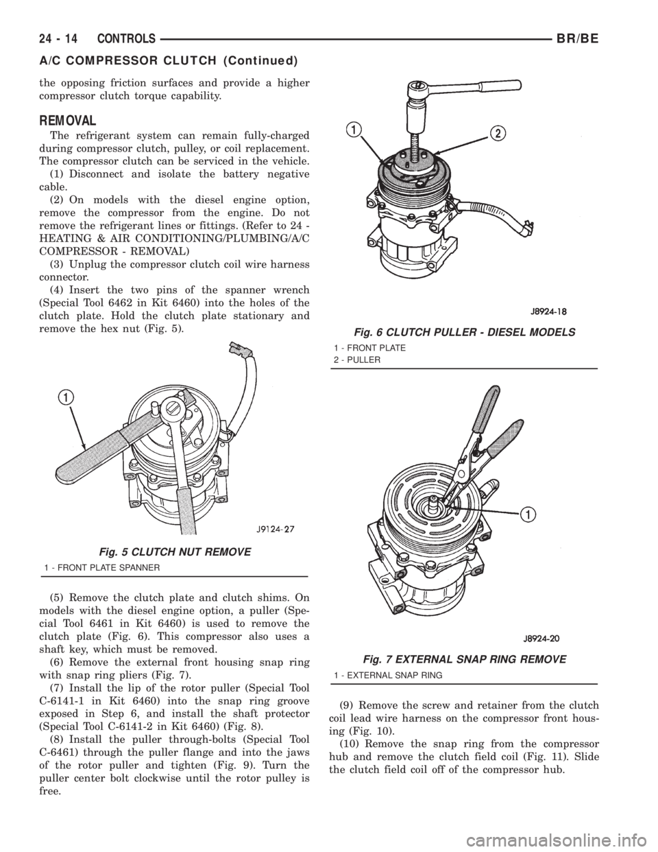
(4) Insert the two pins of the spanner wrench
(Special Tool 6462 in Kit 6460) into the holes of the
clutch plate. Hold the clutch plate stationary and
remove the hex nut (Fig. 5).
(5) Remove the clutch plate and clutch shims. On
models with the diesel engine option, a puller (Spe-
cial Tool 6461 in Kit 6460) is used to remove the
clutch plate (Fig. 6). This compressor also uses a
shaft key, which must be removed.
(6) Remove the external front housing snap ring
with snap ring pliers (Fig. 7).
(7) Install the lip of the rotor puller (Special Tool
C-6141-1 in Kit 6460) into the snap ring groove
exposed in Step 6, and install the shaft protector
(Special Tool C-6141-2 in Kit 6460) (Fig. 8).
(8) Install the puller through-bolts (Special Tool
C-6461) through the puller flange and into the jaws
of the rotor puller and tighten (Fig. 9). Turn the
puller center bolt clockwise until the rotor pulley is
free.(9) Remove the screw and retainer from the clutch
coil lead wire harness on the compressor front hous-
ing (Fig. 10).
(10) Remove the snap ring from the compressor
hub and remove the clutch field coil (Fig. 11). Slide
the clutch field coil off of the compressor hub.
Fig. 5 CLUTCH NUT REMOVE
1 - FRONT PLATE SPANNER
Fig. 6 CLUTCH PULLER - DIESEL MODELS
1 - FRONT PLATE
2 - PULLER
Fig. 7 EXTERNAL SNAP RING REMOVE
1 - EXTERNAL SNAP RING
24 - 14 CONTROLSBR/BE
A/C COMPRESSOR CLUTCH (Continued)
Page 2748 of 2889

tom of the a/c heater control panel. Refer to Heated
Mirrors for more information on this feature.
The heater-only or a/c heater control panel cannot
be repaired. If faulty or damaged, the entire unit
must be replaced. The control knobs and the illumi-
nation lamps are available for service replacement.
DIAGNOSIS AND TESTING - A/C HEATER
CONTROL
Satisfactory heater and air conditioner perfor-
mance depends upon proper operation and adjust-
ment of all operating controls and refrigeration
system components. For circuit descriptions and dia-
grams, (Refer to Appropriate Wiring Information).
These inspections, tests, and adjustments should be
used to locate the cause of a malfunction.
Operation must be tested as described in the fol-
lowing sequence:
(1) Inspect and adjust the serpentine drive belt.
Refer to Cooling for the procedures.
(2) Start the engine and hold the idle speed at
1,300 rpm.
(3) On vehicles with air conditioning, turn the
temperature control knob to the extreme counter-
clockwise (Cool) position, and set the mode control
switch knob to the Bi-Level (A/C) position. The out-
side (recirculation) air door should be open to outside
air. If not OK, (Refer to 24 - HEATING & AIR CON-
DITIONING/CONTROLS - DIAGNOSIS AND TEST-
ING - VACUUM SYSTEM).
(4) Open the vehicle windows. Test the blower
motor operation in all speeds. If not OK, (Refer to 24
- HEATING & AIR CONDITIONING/DISTRIBU-
TION/BLOWER MOTOR - DIAGNOSIS AND TEST-
ING).
(5) On vehicles with air conditioning, the compres-
sor should be running and the air conditioning sys-
tem in operation unless the ambient air temperature
is below about -1É C (30É F). If not OK, (Refer to 24 -
HEATING & AIR CONDITIONING - DIAGNOSIS
AND TESTING - A/C PERFORMANCE).
(6) Check the mode control switch operation. The
heater and air conditioner systems should respond as
described in the owner's manual in the vehicle glove
box to each mode selected. Reduce the engine speed
to normal idle. The vacuum will be high at low idle
and the vacuum actuators should respond quickly. If
not OK, (Refer to 24 - HEATING & AIR CONDI-
TIONING/CONTROLS - DIAGNOSIS AND TEST-
ING - VACUUM SYSTEM).
(7) If the vacuum tests, and the electrical compo-
nent and circuit tests reveal no problems, disassem-
ble the HVAC housing to inspect for mechanical
misalignment or binding of the mode doors. (Refer to
24 - HEATING & AIR CONDITIONING/DISTRIBU-
TION/HVAC HOUSING - DISASSEMBLY)
REMOVAL
WARNING: ON VEHICLES EQUIPPED WITH AIR-
BAGS, DISABLE THE AIRBAG SYSTEM BEFORE
ATTEMPTING ANY STEERING WHEEL, STEERING
COLUMN, OR INSTRUMENT PANEL COMPONENT
DIAGNOSIS OR SERVICE. DISCONNECT AND ISO-
LATE THE BATTERY NEGATIVE (GROUND) CABLE,
THEN WAIT TWO MINUTES FOR THE AIRBAG SYS-
TEM CAPACITOR TO DISCHARGE BEFORE PER-
FORMING FURTHER DIAGNOSIS OR SERVICE. THIS
IS THE ONLY SURE WAY TO DISABLE THE AIRBAG
SYSTEM. FAILURE TO TAKE THE PROPER PRE-
CAUTIONS COULD RESULT IN AN ACCIDENTAL
AIRBAG DEPLOYMENT AND POSSIBLE PERSONAL
INJURY.
(1) Disconnect and isolate the battery negative
cable.
(2) Reach under the instrument panel near the
driver side of the floor panel transmission tunnel and
unplug the a/c heater control to HVAC housing vac-
uum harness connector.
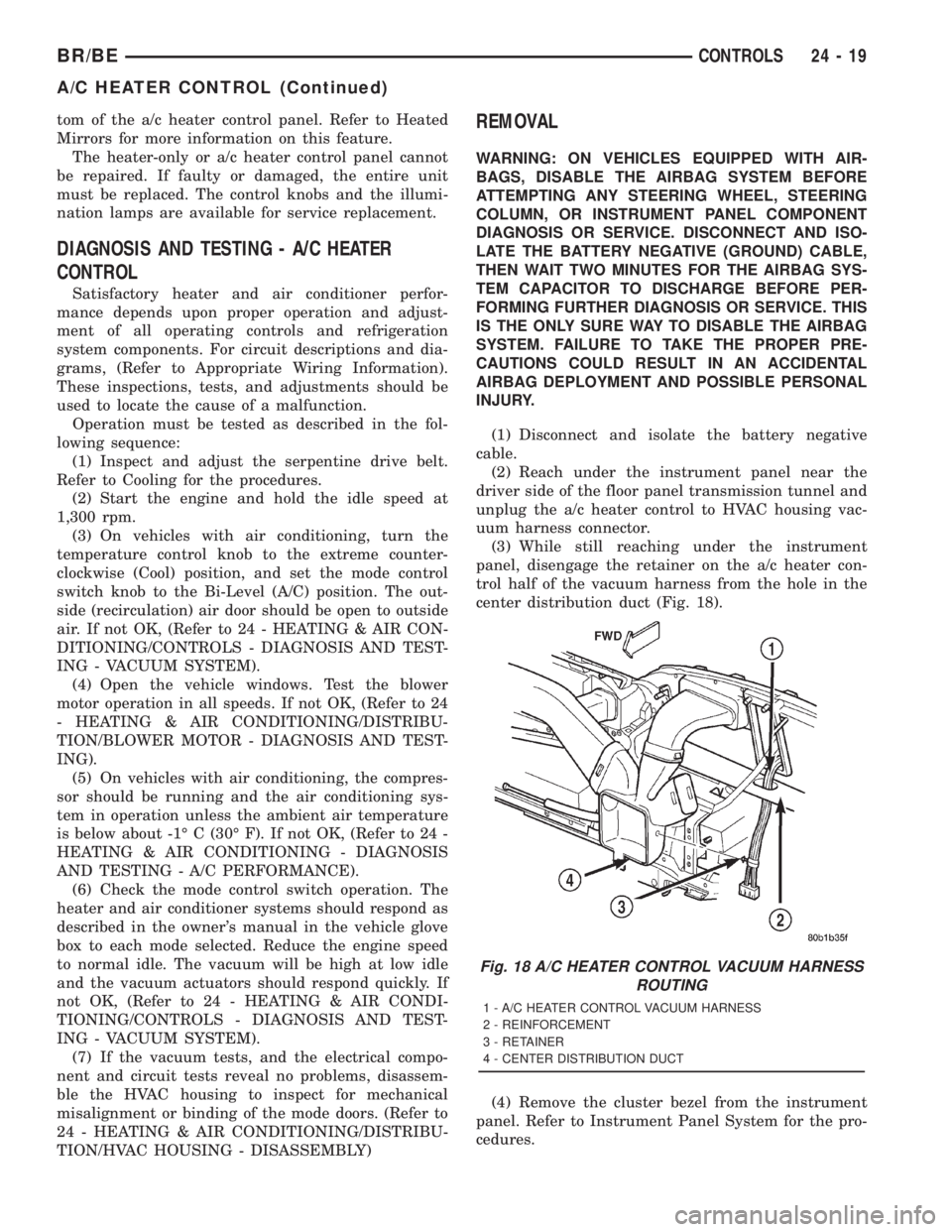
(3) While still reaching under the instrument
panel, disengage the retainer on the a/c heater con-
trol half of the vacuum harness from the hole in the
center distribution duct (Fig. 18).
(4) Remove the cluster bezel from the instrument
panel. Refer to Instrument Panel System for the pro-
cedures.
Fig. 18 A/C HEATER CONTROL VACUUM HARNESS
ROUTING
1 - A/C HEATER CONTROL VACUUM HARNESS
2 - REINFORCEMENT
3 - RETAINER
4 - CENTER DISTRIBUTION DUCT
BR/BECONTROLS 24 - 19
A/C HEATER CONTROL (Continued)
Page 2776 of 2889

the compressor with an engine stethoscope or a long
screwdriver with the handle held to your ear to bet-
ter localize the source of the noise.
(2) Loosen all of the compressor mounting hard-
ware and retighten. Tighten the compressor clutch
mounting nut. Be certain that the clutch coil is
mounted securely to the compressor, and that the
clutch plate and pulley are properly aligned and have
the correct air gap. (Refer to 24 - HEATING & AIR
CONDITIONING/CONTROLS/A/C COMPRESSOR
CLUTCH - INSTALLATION)
(3) To duplicate a high-ambient temperature condi-
tion (high head pressure), restrict the air flow
through the condenser. Install a manifold gauge set
to be certain that the discharge pressure does not
exceed 2760 kPa (400 psi).
(4) Check the refrigerant system plumbing for
incorrect routing, rubbing or interference, which can
cause unusual noises. Also check the refrigerant lines
for kinks or sharp bends that will restrict refrigerant
flow, which can cause noises. (Refer to 24 - HEAT-
ING & AIR CONDITIONING/PLUMBING - CAU-
TION)
(5) If the noise is from opening and closing of the
high pressure relief valve, recover, evacuate, and
recharge the refrigerant system. (Refer to 24 - HEAT-
ING & AIR CONDITIONING/PLUMBING - STAN-
DARD PROCEDURE - REFRIGERANT RECOVERY)
(Refer to 24 - HEATING & AIR CONDITIONING/
PLUMBING - STANDARD PROCEDURE - REFRIG-
ERANT SYSTEM EVACUATE) (Refer to 24 -
HEATING & AIR CONDITIONING/PLUMBING -
STANDARD PROCEDURE - REFRIGERANT SYS-
TEM CHARGE) If the high pressure relief valve still
does not seat properly, replace the compressor.
(6) If the noise is from liquid slugging on the suc-
tion line, replace the accumulator. (Refer to 24 -
HEATING & AIR CONDITIONING/PLUMBING/AC-
CUMULATOR - REMOVAL) Check the refrigerant oil
level and the refrigerant system charge. (Refer to 24
- HEATING & AIR CONDITIONING/PLUMBING/
REFRIGERANT OIL - STANDARD PROCEDURE -
REFRIGERANT OIL LEVEL) (Refer to 24 - HEAT-
ING & AIR CONDITIONING/PLUMBING - SPECI-
FICATIONS - CHARGE CAPACITY) If the liquid
slugging condition continues following accumulator
replacement, replace the compressor.
(7) If the noise continues, replace the compressor
and repeat Step 1.
REMOVAL
WARNING: REVIEW THE WARNINGS AND CAU-
TIONS IN THE FRONT OF THIS SECTION BEFORE
PERFORMING THE FOLLOWING OPERATION.
(Refer to 24 - HEATING & AIR CONDITIONING/PLUMBING - WARNING) (Refer to 24 - HEATING &
AIR CONDITIONING/PLUMBING - CAUTION)
The compressor may be removed and repositioned
without disconnecting the refrigerant lines or dis-
charging the refrigerant system. Discharging is not
necessary if servicing the compressor clutch or clutch
coil, the engine, the cylinder head, or the generator.
(1) Recover the refrigerant from the refrigerant
system. (Refer to 24 - HEATING & AIR CONDI-
TIONING/PLUMBING - STANDARD PROCEDURE -
REFRIGERANT RECOVERY)
(2) Disconnect and isolate the battery negative
cable.
(3) Remove the serpentine drive belt. Refer to
Cooling for the procedures.
(4) Unplug the compressor clutch coil wire harness
connector.
(5) Remove the bolt that secures the refrigerant
line manifold to the compressor. Install plugs in, or
tape over all of the opened refrigerant line fittings.
(6) Remove the four bolts that secure the compres-
sor to the mounting bracket (Fig. 4) or (Fig. 5).
(7) Remove the a/c compressor from the mounting
bracket.
INSTALLATION
WARNING: REVIEW THE WARNINGS AND CAU-
TIONS IN THE FRONT OF THIS SECTION BEFORE
PERFORMING THE FOLLOWING OPERATION.
(Refer to 24 - HEATING & AIR CONDITIONING/
PLUMBING - WARNING) (Refer to 24 - HEATING &
AIR CONDITIONING/PLUMBING - CAUTION)(Refer to
24 - HEATING & AIR CONDITIONING/PLUMBING -
CAUTION - REFRIGERANT HOSES/LINES/TUBES
PRECAUTIONS)
NOTE: If a replacement compressor is being
installed, be certain to check the refrigerant oil
level. (Refer to 24 - HEATING & AIR CONDITIONING/
PLUMBING/REFRIGERANT OIL - STANDARD PRO-
CEDURE) Use only refrigerant oil of the type
recommended for the compressor in the vehicle.
(Refer to 24 - HEATING & AIR CONDITIONING/
PLUMBING/REFRIGERANT OIL - DESCRIPTION)
(1) Install the compressor to the mounting bracket.
Tighten the four mounting bolts to 24 N´m (210 in.
lbs.).
(2) Remove the tape or plugs from all of the
opened refrigerant line fittings. Install the suction
and discharge line manifold to the compressor. (Refer
to 24 - HEATING & AIR CONDITIONING/PLUMB-
ING/A/C SUCTION AND DISCHARGE LINE -
INSTALLATION)
BR/BEPLUMBING 24 - 47
A/C COMPRESSOR (Continued)