2001 DODGE RAM check oil
[x] Cancel search: check oilPage 1444 of 2889
CLEANING
Remove all gasket material from the oil pan and
cylinder block sealing surfaces. Extra effort may be
required around T-joint areas. Clean oil pan and
flush suction tube with a suitable solvent.
INSPECTION
Inspect the oil pan, suction tube, and tube braces
for cracks and damage. Replace any defective compo-
nent. Inspect the oil drain plug and drain hole
threads. Inspect the oil pan sealing surface for
straightness. Repair any minor imperfections with a
ball-peen hammer. Do not attempt to repair an oil
pan by welding.
INSTALLATION
(1) Fill the T-joint between the pan rail/gear hous-
ing and pan rail/rear seal retainer with sealant. Use
MopartSilicone Rubber Adhesive Sealant or equiva-
lent.
(2) Place suction tube in oil pan and guide them
into place (Fig. 151). Using a new tube to oil pump
gasket, install and tighten the suction tube bolts by
hand. Starting with the oil pump inlet bolts, tighten
the bolts to 24 N´m (18 ft. lbs.) torque. Tighten the
remaining tube brace bolts to 24 N´m (18 ft. lbs.)
torque.
(3) Starting in the center and working outward,
tighten the oil pan bolts to 24 N´m (18 ft. lbs.)
torque.
(4) Install the flywheel housing assembly with the
starter motor attached and tighten bolts to 60 N´m
(44 ft. lbs.) torque.
(5) Connect starter motor cables.
(6) Install transmission and transfer case (if
equipped).
(7) Lower vehicle.
(8) Install battery negative cables.
(9) Fill the crankcase with new engine oil.
(10) Start engine and check for leaks. Stop engine,
check oil level, and adjust, if necessary.
OIL PRESSURE RELIEF VALVE
REMOVAL
(1) Disconnect the battery negative cables.
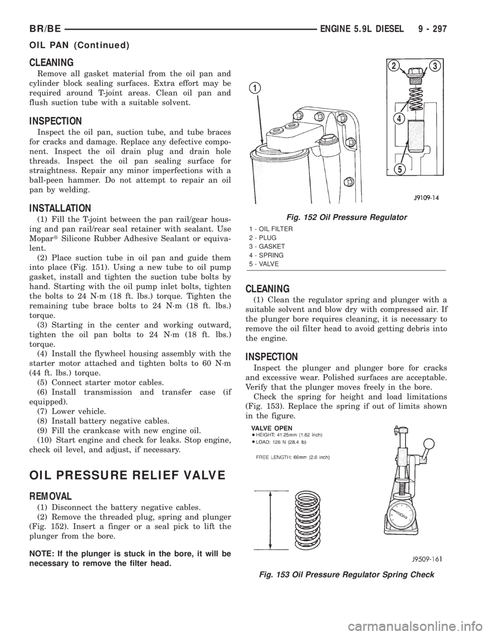
(2) Remove the threaded plug, spring and plunger
(Fig. 152). Insert a finger or a seal pick to lift the
plunger from the bore.
NOTE: If the plunger is stuck in the bore, it will be
necessary to remove the filter head.
CLEANING
(1) Clean the regulator spring and plunger with a
suitable solvent and blow dry with compressed air. If
the plunger bore requires cleaning, it is necessary to
remove the oil filter head to avoid getting debris into
the engine.
INSPECTION
Inspect the plunger and plunger bore for cracks
and excessive wear. Polished surfaces are acceptable.
Verify that the plunger moves freely in the bore.
Check the spring for height and load limitations
(Fig. 153). Replace the spring if out of limits shown
in the figure.
Fig. 152 Oil Pressure Regulator
1 - OIL FILTER
2 - PLUG
3 - GASKET
4 - SPRING
5 - VALVE
Fig. 153 Oil Pressure Regulator Spring Check
BR/BEENGINE 5.9L DIESEL 9 - 297
OIL PAN (Continued)
Page 1445 of 2889
INSTALLATION
(1) Install the plunger, spring, and plug as shown
in (Fig. 152). Tighten the plug to 80 N´m (60 ft. lbs.)
torque.
(2) Connect the battery negative cables.
(3) Start the engine and verify that it has oil pres-
sure.
OIL PRESSURE SENSOR/
SWITCH
DESCRIPTION
The 3±wire, solid-state oil pressure sensor is
installed into the oil pressure galley on the engine
block. It is located below and to the rear of the
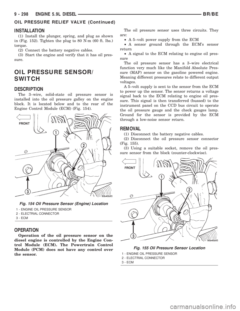
Engine Control Module (ECM) (Fig. 154).
OPERATION
Operation of the oil pressure sensor on the
diesel engine is controlled by the Engine Con-
trol Module (ECM). The Powertrain Control
Module (PCM) does not have any control over
the sensor.The oil pressure sensor uses three circuits. They
are:
²A 5±volt power supply from the ECM
²A sensor ground through the ECM's sensor
return
²A signal to the ECM relating to engine oil pres-
sure
The oil pressure sensor has a 3±wire electrical
function very much like the Manifold Absolute Pres-
sure (MAP) sensor on the gasoline powered engine.
Meaning different pressures relate to different output
voltages.
A 5±volt supply is sent to the sensor from the ECM
to power up the sensor. The sensor returns a voltage
signal back to the ECM relating to engine oil pres-
sure. This signal is then transferred (bussed) to the
instrument panel on the CCD bus circuit to operate
the oil pressure gauge and the check gauges lamp.
Ground for the sensor is provided by the ECM
through a low-noise sensor return.
REMOVAL
(1) Disconnect the battery negative cables.
(2) Disconnect the oil pressure sensor connector
(Fig. 155).
(3) Using a suitable socket, remove the oil pres-
sure sensor from the block (counter-clockwise).
Fig. 154 Oil Pressure Sensor (Engine) Location
1 - ENGINE OIL PRESSURE SENSOR
2 - ELECTRIAL CONNECTOR
3 - ECM
Fig. 155 Oil Pressure Sensor Location
1 - ENGINE OIL PRESSURE SENSOR
2 - ELECTRIAL CONNECTOR
3 - ECM
9 - 298 ENGINE 5.9L DIESELBR/BE
OIL PRESSURE RELIEF VALVE (Continued)
Page 1446 of 2889
INSTALLATION
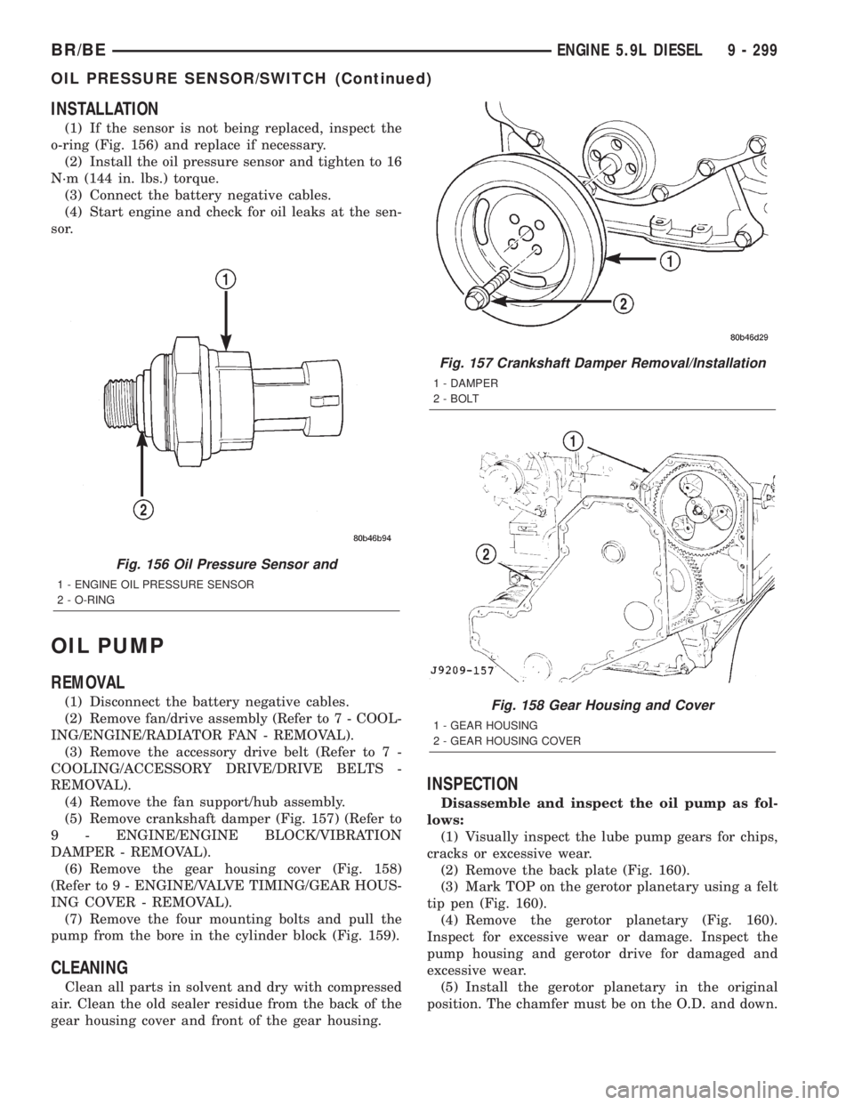
(1) If the sensor is not being replaced, inspect the
o-ring (Fig. 156) and replace if necessary.
(2) Install the oil pressure sensor and tighten to 16
N´m (144 in. lbs.) torque.
(3) Connect the battery negative cables.
(4) Start engine and check for oil leaks at the sen-
sor.
OIL PUMP
REMOVAL
(1) Disconnect the battery negative cables.
(2) Remove fan/drive assembly (Refer to 7 - COOL-
ING/ENGINE/RADIATOR FAN - REMOVAL).
(3) Remove the accessory drive belt (Refer to 7 -
COOLING/ACCESSORY DRIVE/DRIVE BELTS -
REMOVAL).
(4) Remove the fan support/hub assembly.
(5) Remove crankshaft damper (Fig. 157) (Refer to
9 - ENGINE/ENGINE BLOCK/VIBRATION
DAMPER - REMOVAL).
(6) Remove the gear housing cover (Fig. 158)
(Refer to 9 - ENGINE/VALVE TIMING/GEAR HOUS-
ING COVER - REMOVAL).
(7) Remove the four mounting bolts and pull the
pump from the bore in the cylinder block (Fig. 159).
CLEANING
Clean all parts in solvent and dry with compressed
air. Clean the old sealer residue from the back of the
gear housing cover and front of the gear housing.
INSPECTION
Disassemble and inspect the oil pump as fol-
lows:
(1) Visually inspect the lube pump gears for chips,
cracks or excessive wear.
(2) Remove the back plate (Fig. 160).
(3) Mark TOP on the gerotor planetary using a felt
tip pen (Fig. 160).
(4) Remove the gerotor planetary (Fig. 160).
Inspect for excessive wear or damage. Inspect the
pump housing and gerotor drive for damaged and
excessive wear.
(5) Install the gerotor planetary in the original
position. The chamfer must be on the O.D. and down.
Fig. 156 Oil Pressure Sensor and
1 - ENGINE OIL PRESSURE SENSOR
2 - O-RING
Fig. 157 Crankshaft Damper Removal/Installation
1 - DAMPER
2 - BOLT
Fig. 158 Gear Housing and Cover
1 - GEAR HOUSING
2 - GEAR HOUSING COVER
BR/BEENGINE 5.9L DIESEL 9 - 299
OIL PRESSURE SENSOR/SWITCH (Continued)
Page 1448 of 2889
(7) Apply a bead of MopartSilicone Rubber Adhe-
sive Sealant or equivalent to the gear housing cover
sealing surface.(8) Install the gear housing cover (Refer to 9 -
ENGINE/VALVE TIMING/GEAR HOUSING COVER
- INSTALLATION).
(9) Install the vibration damper (Refer to 9 -
ENGINE/ENGINE BLOCK/VIBRATION DAMPER -
INSTALLATION).
(10) Install the fan support/hub assembly and
torque bolts to 24 N´m (18 ft. lbs.).
(11) Install the accessory drive belt (Refer to 7 -
COOLING/ACCESSORY DRIVE/DRIVE BELTS -
INSTALLATION).
(12) Install the cooling fan (Refer to 7 - COOLING/
ENGINE/RADIATOR FAN - INSTALLATION).
(13) Connect battery negative cables.
(14) Start engine and check for oil leaks.
INTAKE MANIFOLD
REMOVAL
(1) Disconnect the battery negative cables.
(2) Remove the charge air cooler outlet tube from
the air inlet housing (Fig. 167).
(3) Remove the engine oil dipstick tube mounting
bolt (Fig. 167). Position dipstick tube to the side.
(4) Disconnect the air grid heater power cables at
the cable mounting studs (Fig. 168).
(5) Remove the four (4) air inlet housing mounting
bolts (Fig. 168) and remove the housing from top of
the heater elements.
(6) Remove the intake air grid heater from the
manifold (Fig. 169).
(7) Remove the high pressure fuel lines.(Refer to
14 - FUEL SYSTEM/FUEL DELIVERY/FUEL LINES
- REMOVAL).
(8) Remove the remaining intake manifold cover-
to-cylinder head bolts.
(9) Remove the intake manifold cover and gasket.
Keep the gasket material and any other material out
of the air intake.
(10) Clean the intake manifold cover and cylinder
head sealing surface.
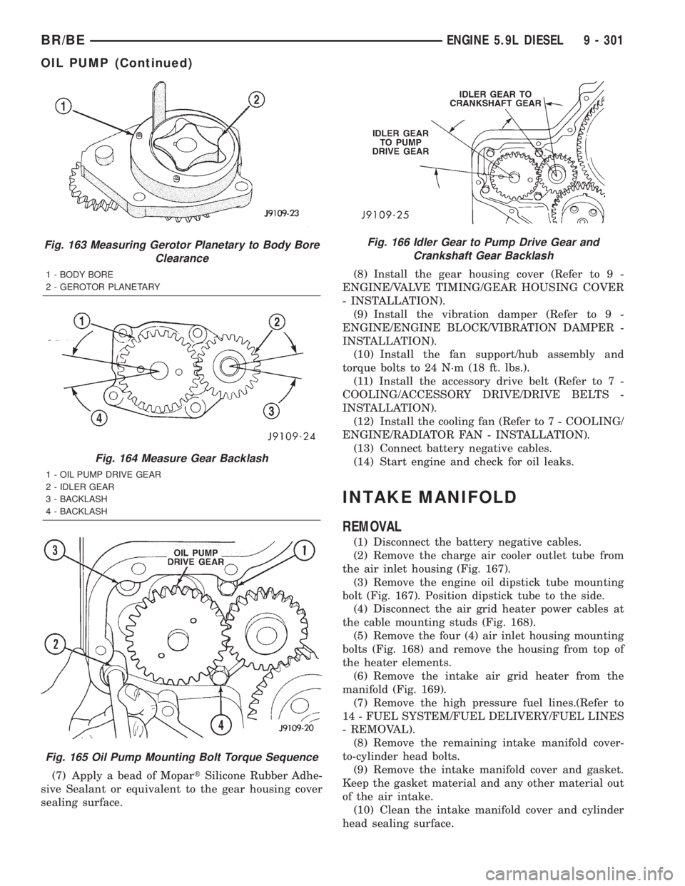
Fig. 163 Measuring Gerotor Planetary to Body Bore
Clearance
1 - BODY BORE
2 - GEROTOR PLANETARY
Fig. 164 Measure Gear Backlash
1 - OIL PUMP DRIVE GEAR
2 - IDLER GEAR
3 - BACKLASH
4 - BACKLASH
Fig. 165 Oil Pump Mounting Bolt Torque Sequence
Fig. 166 Idler Gear to Pump Drive Gear and
Crankshaft Gear Backlash
BR/BEENGINE 5.9L DIESEL 9 - 301
OIL PUMP (Continued)
Page 1451 of 2889
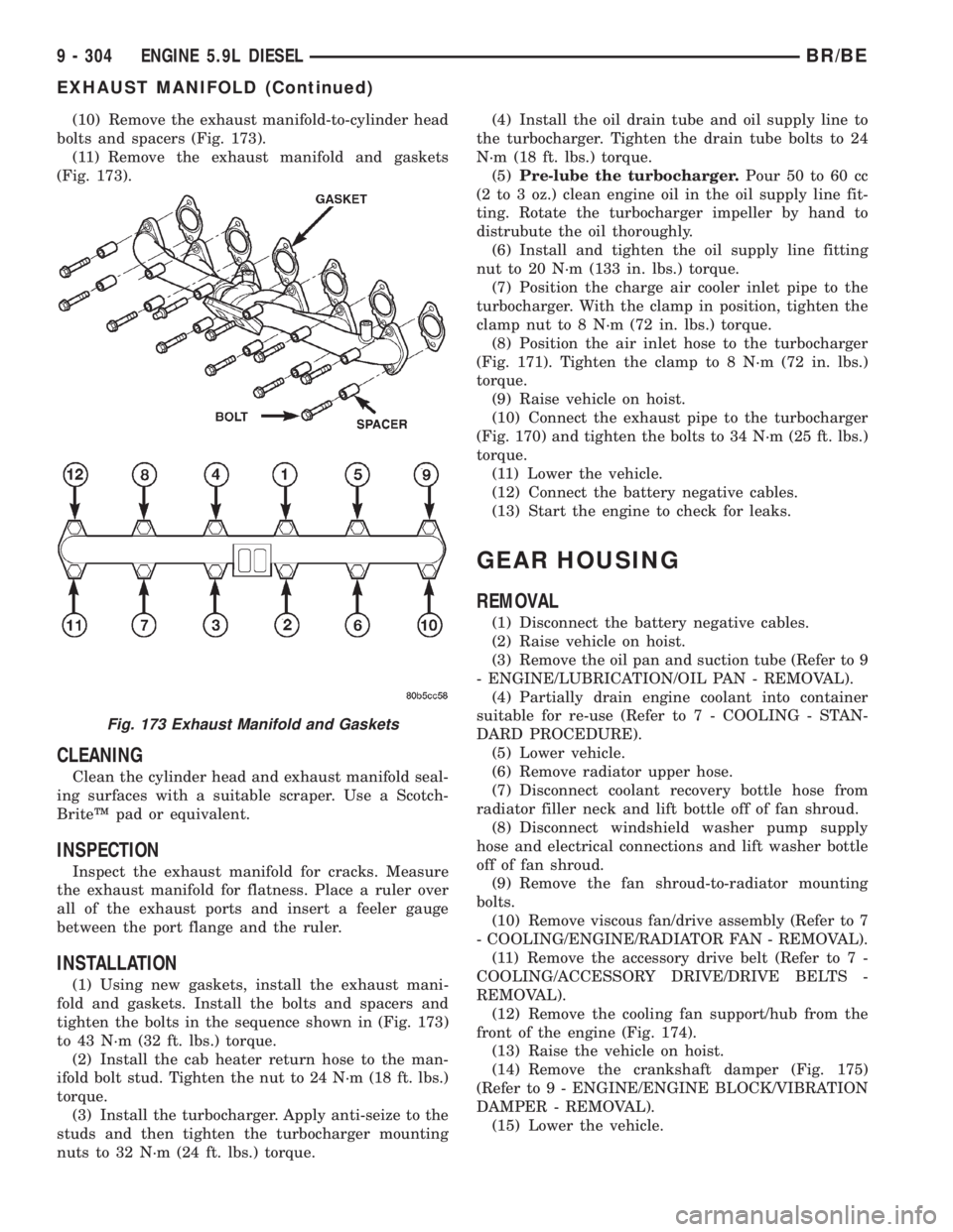
(10) Remove the exhaust manifold-to-cylinder head
bolts and spacers (Fig. 173).
(11) Remove the exhaust manifold and gaskets
(Fig. 173).
CLEANING
Clean the cylinder head and exhaust manifold seal-
ing surfaces with a suitable scraper. Use a Scotch-
BriteŸ pad or equivalent.
INSPECTION
Inspect the exhaust manifold for cracks. Measure
the exhaust manifold for flatness. Place a ruler over
all of the exhaust ports and insert a feeler gauge
between the port flange and the ruler.
INSTALLATION
(1) Using new gaskets, install the exhaust mani-
fold and gaskets. Install the bolts and spacers and
tighten the bolts in the sequence shown in (Fig. 173)
to 43 N´m (32 ft. lbs.) torque.
(2) Install the cab heater return hose to the man-
ifold bolt stud. Tighten the nut to 24 N´m (18 ft. lbs.)
torque.
(3) Install the turbocharger. Apply anti-seize to the
studs and then tighten the turbocharger mounting
nuts to 32 N´m (24 ft. lbs.) torque.(4) Install the oil drain tube and oil supply line to
the turbocharger. Tighten the drain tube bolts to 24
N´m (18 ft. lbs.) torque.
(5)Pre-lube the turbocharger.Pour 50 to 60 cc
(2 to 3 oz.) clean engine oil in the oil supply line fit-
ting. Rotate the turbocharger impeller by hand to
distrubute the oil thoroughly.
(6) Install and tighten the oil supply line fitting
nut to 20 N´m (133 in. lbs.) torque.
(7) Position the charge air cooler inlet pipe to the
turbocharger. With the clamp in position, tighten the
clamp nut to 8 N´m (72 in. lbs.) torque.
(8) Position the air inlet hose to the turbocharger
(Fig. 171). Tighten the clamp to 8 N´m (72 in. lbs.)
torque.
(9) Raise vehicle on hoist.
(10) Connect the exhaust pipe to the turbocharger
(Fig. 170) and tighten the bolts to 34 N´m (25 ft. lbs.)
torque.
(11) Lower the vehicle.
(12) Connect the battery negative cables.
(13) Start the engine to check for leaks.
GEAR HOUSING
REMOVAL
(1) Disconnect the battery negative cables.
(2) Raise vehicle on hoist.
(3) Remove the oil pan and suction tube (Refer to 9
- ENGINE/LUBRICATION/OIL PAN - REMOVAL).
(4) Partially drain engine coolant into container
suitable for re-use (Refer to 7 - COOLING - STAN-
DARD PROCEDURE).
(5) Lower vehicle.
(6) Remove radiator upper hose.
(7) Disconnect coolant recovery bottle hose from
radiator filler neck and lift bottle off of fan shroud.
(8) Disconnect windshield washer pump supply
hose and electrical connections and lift washer bottle
off of fan shroud.
(9) Remove the fan shroud-to-radiator mounting
bolts.
(10) Remove viscous fan/drive assembly (Refer to 7
- COOLING/ENGINE/RADIATOR FAN - REMOVAL).
(11) Remove the accessory drive belt (Refer to 7 -
COOLING/ACCESSORY DRIVE/DRIVE BELTS -
REMOVAL).
(12) Remove the cooling fan support/hub from the
front of the engine (Fig. 174).
(13) Raise the vehicle on hoist.
(14) Remove the crankshaft damper (Fig. 175)
(Refer to 9 - ENGINE/ENGINE BLOCK/VIBRATION
DAMPER - REMOVAL).
(15) Lower the vehicle.
Fig. 173 Exhaust Manifold and Gaskets
9 - 304 ENGINE 5.9L DIESELBR/BE
EXHAUST MANIFOLD (Continued)
Page 1472 of 2889
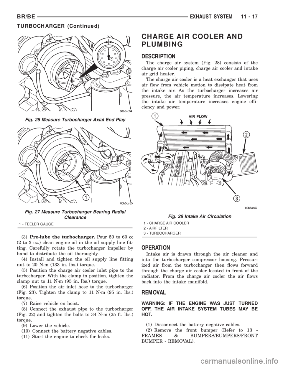
(3)Pre-lube the turbocharger.Pour 50 to 60 cc
(2 to 3 oz.) clean engine oil in the oil supply line fit-
ting. Carefully rotate the turbocharger impeller by
hand to distribute the oil thoroughly.
(4) Install and tighten the oil supply line fitting
nut to 20 N´m (133 in. lbs.) torque.
(5) Position the charge air cooler inlet pipe to the
turbocharger. With the clamp in position, tighten the
clamp nut to 11 N´m (95 in. lbs.) torque.
(6) Position the air inlet hose to the turbocharger
(Fig. 23). Tighten the clamp to 11 N´m (95 in. lbs.)
torque.
(7) Raise vehicle on hoist.
(8) Connect the exhaust pipe to the turbocharger
(Fig. 22) and tighten the bolts to 34 N´m (25 ft. lbs.)
torque.
(9) Lower the vehicle.
(10) Connect the battery negative cables.
(11) Start the engine to check for leaks.
CHARGE AIR COOLER AND
PLUMBING
DESCRIPTION
The charge air system (Fig. 28) consists of the
charge air cooler piping, charge air cooler and intake
air grid heater.
The charge air cooler is a heat exchanger that uses
air flow from vehicle motion to dissipate heat from
the intake air. As the turbocharger increases air
pressure, the air temperature increases. Lowering
the intake air temperature increases engine effi-
ciency and power.
OPERATION
Intake air is drawn through the air cleaner and
into the turbocharger compressor housing. Pressur-
ized air from the turbocharger then flows forward
through the charge air cooler located in front of the
radiator. From the charge air cooler the air flows
back into the intake manifold.
REMOVAL
WARNING: IF THE ENGINE WAS JUST TURNED
OFF, THE AIR INTAKE SYSTEM TUBES MAY BE
HOT.
(1) Disconnect the battery negative cables.
(2) Remove the front bumper (Refer to 13 -
FRAMES & BUMPERS/BUMPERS/FRONT
BUMPER - REMOVAL).
Fig. 26 Measure Turbocharger Axial End Play
Fig. 27 Measure Turbocharger Bearing Radial
Clearance
1 - FEELER GAUGE
Fig. 28 Intake Air Circulation
1 - CHARGE AIR COOLER
2 - AIRFILTER
3 - TURBOCHARGER
BR/BEEXHAUST SYSTEM 11 - 17
TURBOCHARGER (Continued)
Page 1505 of 2889
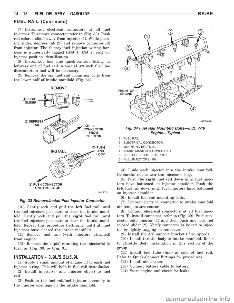
(7) Disconnect electrical connectors at all fuel
injectors. To remove connector refer to (Fig. 33). Push
red colored slider away from injector (1). While push-
ing slider, depress tab (2) and remove connector (3)
from injector. The factory fuel injection wiring har-
ness is numerically tagged (INJ 1, INJ 2, etc.) for
injector position identification.
(8) Disconnect fuel line quick-connect fitting at
left-rear end of fuel rail. A special 3/8 inch fuel line
disconnection tool will be necessary.
(9) Remove the six fuel rail mounting bolts from
the lower half of intake manifold (Fig. 34).
(10) Gently rock and pull theleftfuel rail until
the fuel injectors just start to clear the intake mani-
fold. Gently rock and pull therightfuel rail until
the fuel injectors just start to clear the intake mani-
fold. Repeat this procedure (left/right) until all fuel
injectors have cleared the intake manifold.
(11) Remove fuel rail (with injectors attached)
from engine.
(12) Remove the clip(s) retaining the injector(s) to
fuel rail (Fig. 30) or (Fig. 31).
INSTALLATION - 3.9L/5.2L/5.9L
(1) Apply a small amount of engine oil to each fuel
injector o-ring. This will help in fuel rail installation.
(2) Install injector(s) and injector clip(s) to fuel
rail.
(3) Position the fuel rail/fuel injector assembly to
the injector openings on the intake manifold.(4) Guide each injector into the intake manifold.
Be careful not to tear the injector o-ring.
(5) Push therightfuel rail down until fuel injec-
tors have bottomed on injector shoulder. Push the
leftfuel rail down until fuel injectors have bottomed
on injector shoulder.
(6) Install fuel rail mounting bolts.
(7) Connect electrical connector to intake manifold
air temperature sensor.
(8) Connect electrical connectors at all fuel injec-
tors. To install connector, refer to (Fig. 29). Push con-
nector onto injector (1) and then push and lock red
colored slider (2). Verify connector is locked to injec-
tor by lightly tugging on connector.
(9) Install the A/C support bracket (if equipped).
(10) Install throttle body to intake manifold. Refer
to Throttle Body installation in this section of the
group.
(11) Install fuel tube (line) at side of fuel rail.
Refer to Quick-Connect Fittings for procedures.
(12) Install air cleaner.
(13) Connect battery cable to battery.
(14) Start engine and check for leaks.
Fig. 33 Remove/Install Fuel Injector Connector
Fig. 34 Fuel Rail Mounting BoltsÐ8.0L V-10
EngineÐTypical
1 - FUEL RAIL
2 - ELECTRICAL CONNECTOR
3 - MOUNTING BOLTS (6)
4 - INTAKE MANIFOLD LOWER HALF
5 - FUEL PRESSURE TEST PORT
6 - FUEL INJECTORS (10)
14 - 18 FUEL DELIVERY - GASOLINEBR/BE
FUEL RAIL (Continued)
Page 1506 of 2889
INSTALLATION - 8.0L
(1) Apply a small amount of engine oil to each fuel
injector o-ring. This will help in fuel rail installation.
(2) Install injector(s) and injector clip(s) to fuel
rail.
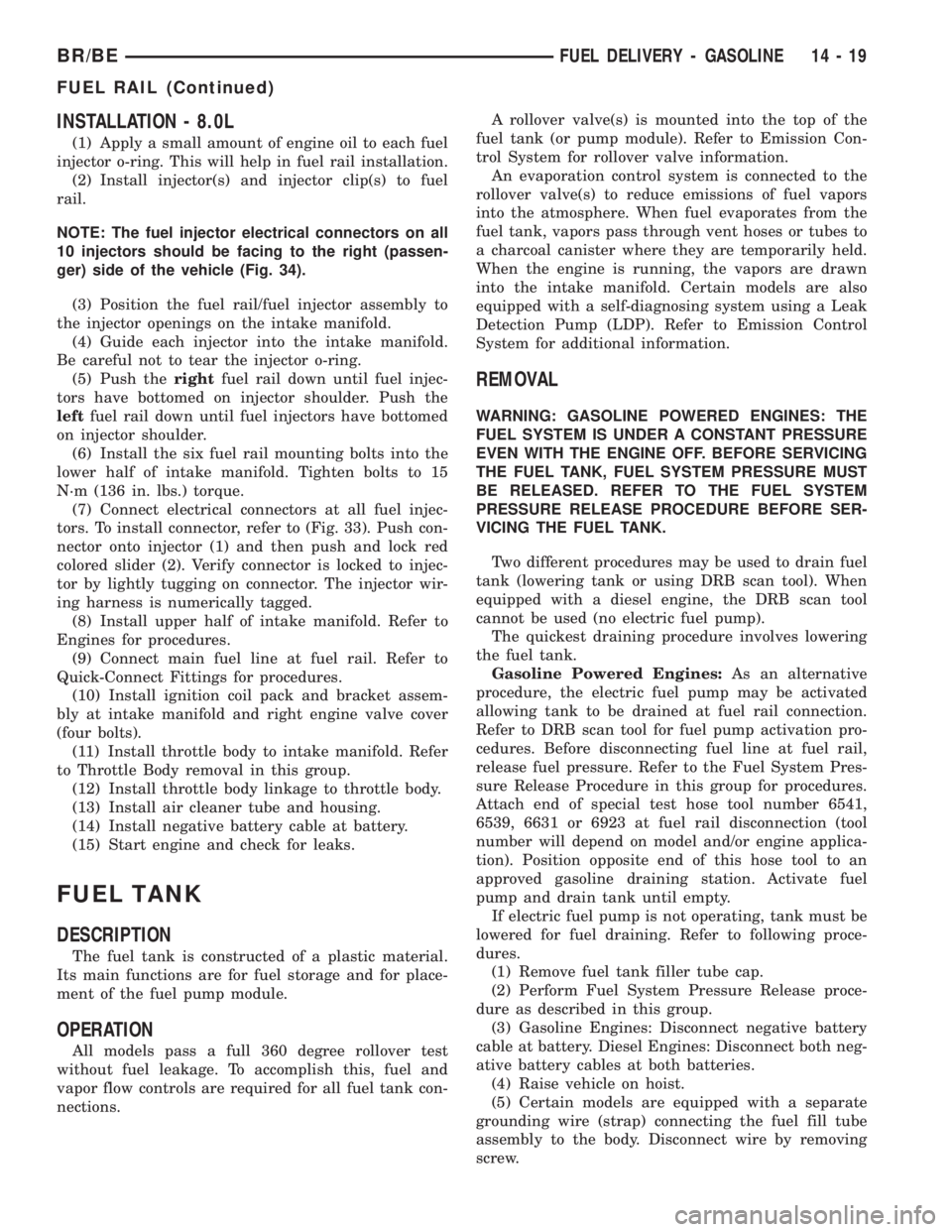
NOTE: The fuel injector electrical connectors on all
10 injectors should be facing to the right (passen-
ger) side of the vehicle (Fig. 34).
(3) Position the fuel rail/fuel injector assembly to
the injector openings on the intake manifold.
(4) Guide each injector into the intake manifold.
Be careful not to tear the injector o-ring.
(5) Push therightfuel rail down until fuel injec-
tors have bottomed on injector shoulder. Push the
leftfuel rail down until fuel injectors have bottomed
on injector shoulder.
(6) Install the six fuel rail mounting bolts into the
lower half of intake manifold. Tighten bolts to 15
N´m (136 in. lbs.) torque.
(7) Connect electrical connectors at all fuel injec-
tors. To install connector, refer to (Fig. 33). Push con-
nector onto injector (1) and then push and lock red
colored slider (2). Verify connector is locked to injec-
tor by lightly tugging on connector. The injector wir-
ing harness is numerically tagged.
(8) Install upper half of intake manifold. Refer to
Engines for procedures.
(9) Connect main fuel line at fuel rail. Refer to
Quick-Connect Fittings for procedures.
(10) Install ignition coil pack and bracket assem-
bly at intake manifold and right engine valve cover
(four bolts).
(11) Install throttle body to intake manifold. Refer
to Throttle Body removal in this group.
(12) Install throttle body linkage to throttle body.
(13) Install air cleaner tube and housing.
(14) Install negative battery cable at battery.
(15) Start engine and check for leaks.
FUEL TANK
DESCRIPTION
The fuel tank is constructed of a plastic material.
Its main functions are for fuel storage and for place-
ment of the fuel pump module.
OPERATION
All models pass a full 360 degree rollover test
without fuel leakage. To accomplish this, fuel and
vapor flow controls are required for all fuel tank con-
nections.A rollover valve(s) is mounted into the top of the
fuel tank (or pump module). Refer to Emission Con-
trol System for rollover valve information.
An evaporation control system is connected to the
rollover valve(s) to reduce emissions of fuel vapors
into the atmosphere. When fuel evaporates from the
fuel tank, vapors pass through vent hoses or tubes to
a charcoal canister where they are temporarily held.
When the engine is running, the vapors are drawn
into the intake manifold. Certain models are also
equipped with a self-diagnosing system using a Leak
Detection Pump (LDP). Refer to Emission Control
System for additional information.
REMOVAL
WARNING: GASOLINE POWERED ENGINES: THE
FUEL SYSTEM IS UNDER A CONSTANT PRESSURE
EVEN WITH THE ENGINE OFF. BEFORE SERVICING
THE FUEL TANK, FUEL SYSTEM PRESSURE MUST
BE RELEASED. REFER TO THE FUEL SYSTEM
PRESSURE RELEASE PROCEDURE BEFORE SER-
VICING THE FUEL TANK.
Two different procedures may be used to drain fuel
tank (lowering tank or using DRB scan tool). When
equipped with a diesel engine, the DRB scan tool
cannot be used (no electric fuel pump).
The quickest draining procedure involves lowering
the fuel tank.
Gasoline Powered Engines:As an alternative
procedure, the electric fuel pump may be activated
allowing tank to be drained at fuel rail connection.
Refer to DRB scan tool for fuel pump activation pro-
cedures. Before disconnecting fuel line at fuel rail,
release fuel pressure. Refer to the Fuel System Pres-
sure Release Procedure in this group for procedures.
Attach end of special test hose tool number 6541,
6539, 6631 or 6923 at fuel rail disconnection (tool
number will depend on model and/or engine applica-
tion). Position opposite end of this hose tool to an
approved gasoline draining station. Activate fuel
pump and drain tank until empty.
If electric fuel pump is not operating, tank must be
lowered for fuel draining. Refer to following proce-
dures.
(1) Remove fuel tank filler tube cap.
(2) Perform Fuel System Pressure Release proce-
dure as described in this group.
(3) Gasoline Engines: Disconnect negative battery
cable at battery. Diesel Engines: Disconnect both neg-
ative battery cables at both batteries.
(4) Raise vehicle on hoist.
(5) Certain models are equipped with a separate
grounding wire (strap) connecting the fuel fill tube
assembly to the body. Disconnect wire by removing
screw.
BR/BEFUEL DELIVERY - GASOLINE 14 - 19
FUEL RAIL (Continued)