2001 DODGE RAM check oil
[x] Cancel search: check oilPage 1700 of 2889
case top surface and in the housing/adapter are tight
and in good condition.
Run a tap through the gear case bolt holes if the
threads need minor cleanup. Helicoil inserts can be
used to repair seriously damaged threaded holes if
necessary.
Be sure all case and housing/adapter sealing and
mating surfaces are free of burrs and nicks. This is
especially important as gaskets are not used in the
transmission. Minor nicks and scratches on the seal-
ing surfaces can be dressed off with a fine tooth file
or oil stone.
Replace the gear case or housing/adapter if cracked
or broken. Do not attempt to repair this type of dam-
age by welding or brazing.
Check condition of the countershaft fifth gear com-
ponents. This includes the shift lug and rail located
in the gear case and the rail bushings.
Inspect the gear and hub assembly. Minor burrs
can be cleaned up with an oil stone. However, the
gear and hub assembly should be replaced if the
teeth or splines are excessively worn, or damaged.
The synchro sleeve should also be replaced if worn or
damaged in any way. Do not reuse synchro struts
that are worn or springs that are collapsed or
severely distorted. Replace worn distorted synchro
parts to avoid shift problems after assembly and
installation.
The shift fork should be inspected for evidence of
wear and distortion. Check fit of the sleeve in the
fork to be sure the two parts fit and work smoothly.
Replace the fork if the roll pin holes are worn over-
size or damaged. Do not attempt to salvage a worn
fork. It will cause shift problems later on. Replace
shift fork roll pins if necessary or if doubt exists
about their condition.
The bearings should be examined carefully for
wear, roughness, flat spots, pitting or other damage.
Replace the bearings if necessary.
Inspect the blocker ring and clutch gear. replace
either part if worn or damaged in any way. Also be
sure replacement parts fit properly before proceeding
with assembly.
Examine the 1-2 synchro hub and sleeve for wear
or damage. Replace sleeve and hub if the splines are
worn, chipped or damaged.
Replace the synchro struts if worn, or chipped. Also
replace the springs if collapsed, distorted or broken.
Inspect the mainshaft geartrain components.
Check teeth on all gears, hubs, clutch gears, stop
rings and clutch rings. The teeth must be in good
condition and not worn, cracked or chipped. Replace
any component that exhibits wear or damage.
Examine the synchro stop rings, clutch rings and
clutch gears. Replace any part that exhibits wear,distortion or damage. Replace the clutch rings if the
friction material is burned, flaking off or worn.
Inspect all of the thrust washers and locating pins.
Replace the pins if bent or worn. Replace the wash-
ers if worn or the locating pin notches are distorted.
Check condition of the synchro struts and springs.
Replace these parts if worn, cracked or distorted.
ASSEMBLY
NOTE: Gaskets are not used in the NV4500 trans-
mission. Use MoparTSilicone Sealer or equivalent
on all gear case and extension housing sealing sur-
faces.
COUNTERSHAFT AND REVERSE IDLER GEAR
(1) Install countershaft front bearing cup in case
with Handle C-4171 and Installer 6061-1.
(2) Install front bearing on countershaft with
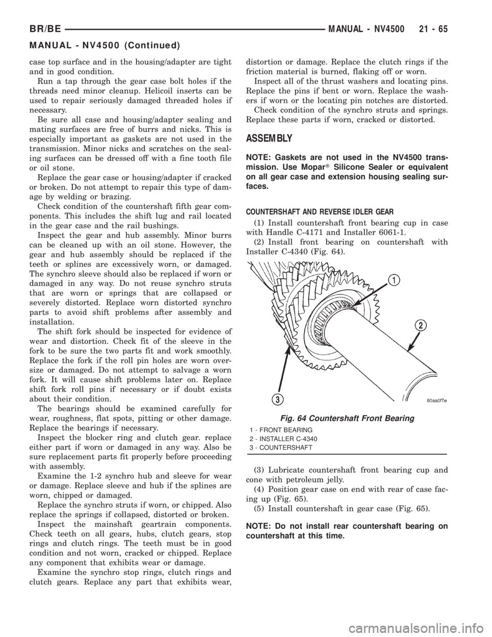
Installer C-4340 (Fig. 64).
(3) Lubricate countershaft front bearing cup and
cone with petroleum jelly.
(4) Position gear case on end with rear of case fac-
ing up (Fig. 65).
(5) Install countershaft in gear case (Fig. 65).
NOTE: Do not install rear countershaft bearing on
countershaft at this time.
Fig. 64 Countershaft Front Bearing
1 - FRONT BEARING
2 - INSTALLER C-4340
3 - COUNTERSHAFT
BR/BEMANUAL - NV4500 21 - 65
MANUAL - NV4500 (Continued)
Page 1711 of 2889
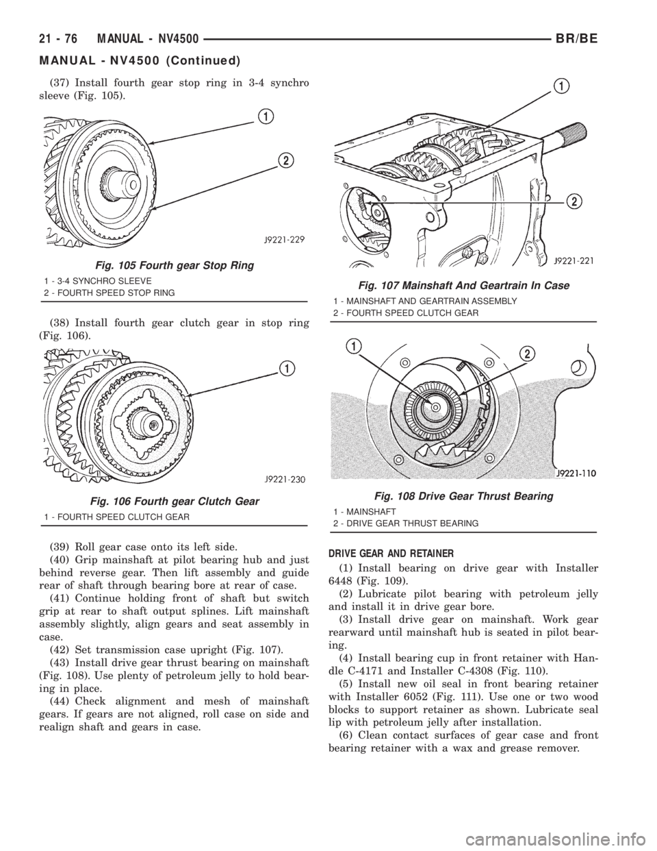
(37) Install fourth gear stop ring in 3-4 synchro
sleeve (Fig. 105).
(38) Install fourth gear clutch gear in stop ring
(Fig. 106).
(39) Roll gear case onto its left side.
(40) Grip mainshaft at pilot bearing hub and just
behind reverse gear. Then lift assembly and guide
rear of shaft through bearing bore at rear of case.
(41) Continue holding front of shaft but switch
grip at rear to shaft output splines. Lift mainshaft
assembly slightly, align gears and seat assembly in
case.
(42) Set transmission case upright (Fig. 107).
(43) Install drive gear thrust bearing on mainshaft
(Fig. 108). Use plenty of petroleum jelly to hold bear-
ing in place.
(44) Check alignment and mesh of mainshaft
gears. If gears are not aligned, roll case on side and
realign shaft and gears in case.DRIVE GEAR AND RETAINER
(1) Install bearing on drive gear with Installer
6448 (Fig. 109).
(2) Lubricate pilot bearing with petroleum jelly
and install it in drive gear bore.
(3) Install drive gear on mainshaft. Work gear
rearward until mainshaft hub is seated in pilot bear-
ing.
(4) Install bearing cup in front retainer with Han-
dle C-4171 and Installer C-4308 (Fig. 110).
(5) Install new oil seal in front bearing retainer
with Installer 6052 (Fig. 111). Use one or two wood
blocks to support retainer as shown. Lubricate seal
lip with petroleum jelly after installation.
(6) Clean contact surfaces of gear case and front
bearing retainer with a wax and grease remover.
Fig. 105 Fourth gear Stop Ring
1 - 3-4 SYNCHRO SLEEVE
2 - FOURTH SPEED STOP RING
Fig. 106 Fourth gear Clutch Gear
1 - FOURTH SPEED CLUTCH GEAR
Fig. 107 Mainshaft And Geartrain In Case
1 - MAINSHAFT AND GEARTRAIN ASSEMBLY
2 - FOURTH SPEED CLUTCH GEAR
Fig. 108 Drive Gear Thrust Bearing
1 - MAINSHAFT
2 - DRIVE GEAR THRUST BEARING
21 - 76 MANUAL - NV4500BR/BE
MANUAL - NV4500 (Continued)
Page 1728 of 2889
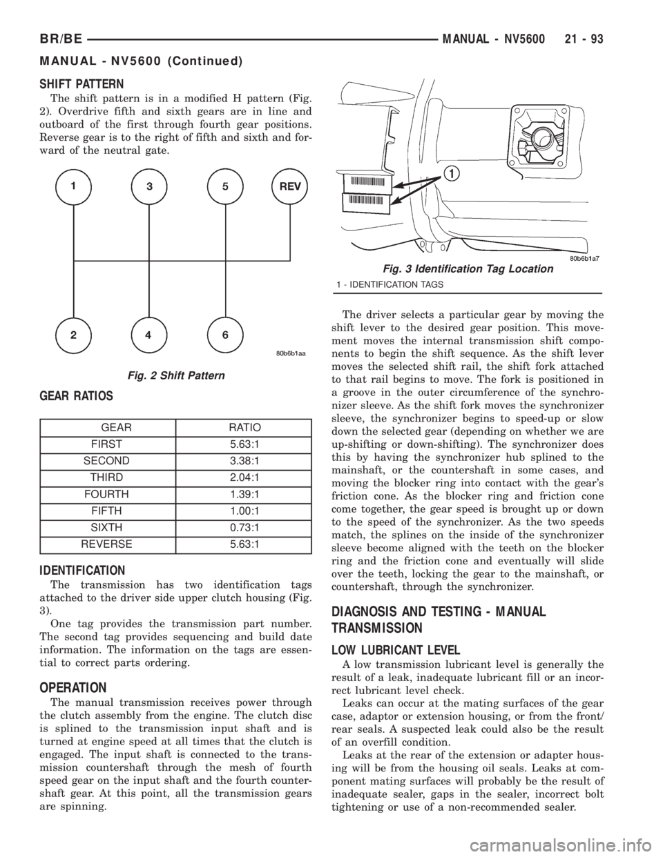
SHIFT PATTERN
The shift pattern is in a modified H pattern (Fig.
2). Overdrive fifth and sixth gears are in line and
outboard of the first through fourth gear positions.
Reverse gear is to the right of fifth and sixth and for-
ward of the neutral gate.
GEAR RATIOS
GEAR RATIO
FIRST 5.63:1
SECOND 3.38:1
THIRD 2.04:1
FOURTH 1.39:1
FIFTH 1.00:1
SIXTH 0.73:1
REVERSE 5.63:1
IDENTIFICATION
The transmission has two identification tags
attached to the driver side upper clutch housing (Fig.
3).
One tag provides the transmission part number.
The second tag provides sequencing and build date
information. The information on the tags are essen-
tial to correct parts ordering.
OPERATION
The manual transmission receives power through
the clutch assembly from the engine. The clutch disc
is splined to the transmission input shaft and is
turned at engine speed at all times that the clutch is
engaged. The input shaft is connected to the trans-
mission countershaft through the mesh of fourth
speed gear on the input shaft and the fourth counter-
shaft gear. At this point, all the transmission gears
are spinning.The driver selects a particular gear by moving the
shift lever to the desired gear position. This move-
ment moves the internal transmission shift compo-
nents to begin the shift sequence. As the shift lever
moves the selected shift rail, the shift fork attached
to that rail begins to move. The fork is positioned in
a groove in the outer circumference of the synchro-
nizer sleeve. As the shift fork moves the synchronizer
sleeve, the synchronizer begins to speed-up or slow
down the selected gear (depending on whether we are
up-shifting or down-shifting). The synchronizer does
this by having the synchronizer hub splined to the
mainshaft, or the countershaft in some cases, and
moving the blocker ring into contact with the gear's
friction cone. As the blocker ring and friction cone
come together, the gear speed is brought up or down
to the speed of the synchronizer. As the two speeds
match, the splines on the inside of the synchronizer
sleeve become aligned with the teeth on the blocker
ring and the friction cone and eventually will slide
over the teeth, locking the gear to the mainshaft, or
countershaft, through the synchronizer.
DIAGNOSIS AND TESTING - MANUAL
TRANSMISSION
LOW LUBRICANT LEVEL
A low transmission lubricant level is generally the
result of a leak, inadequate lubricant fill or an incor-
rect lubricant level check.
Leaks can occur at the mating surfaces of the gear
case, adaptor or extension housing, or from the front/
rear seals. A suspected leak could also be the result
of an overfill condition.
Leaks at the rear of the extension or adapter hous-
ing will be from the housing oil seals. Leaks at com-
ponent mating surfaces will probably be the result of
inadequate sealer, gaps in the sealer, incorrect bolt
tightening or use of a non-recommended sealer.
Fig. 2 Shift Pattern
Fig. 3 Identification Tag Location
1 - IDENTIFICATION TAGS
BR/BEMANUAL - NV5600 21 - 93
MANUAL - NV5600 (Continued)
Page 1744 of 2889
CLEANING - TRANSMISSION
Clean the gears, bearings shafts, extension/adapter
housing and gear case with solvent. Dry all parts
except the bearings with compressed air. Allow the
bearings to either air dry or wipe them dry with
clean shop towels.
Run a tap through the gear case bolt holes if the
threads need minor cleanup. Helicoil inserts can be
used to repair seriously damaged threaded holes if
necessary.
INSPECTION - TRANSMISSION
Inspect the reverse idler gear, bearings, shaft and
thrust washers. Replace the bearings if the rollers
are worn, chipped, cracked, flat-spotted or brinnelled.
Or if the bearing cage is damaged or distorted.
Replace the thrust washers if cracked, chipped or
worn. Replace the gear if the teeth are chipped,
cracked or worn thin.
Inspect the drive gear and bearings. Minor
scratches and burrs on the gear surfaces can be
reduced with an oil stone and 400 grit paper wetted
with oil. Replace either bearing if worn, or damaged.
Replace the gear if any teeth, splines, or bearing sur-
faces are also worn or damaged.
Inspect the front bearing retainer and bearing cup.
Replace the bearing cup if scored, cracked, brinnelled
or rough. Check the release bearing slide surface of
the retainer carefully. Minor corrosion, nicks, or pit-
ting can be smoothed with 400 grit emery and pol-
ished out with crocus cloth. Wet the abrasive paper
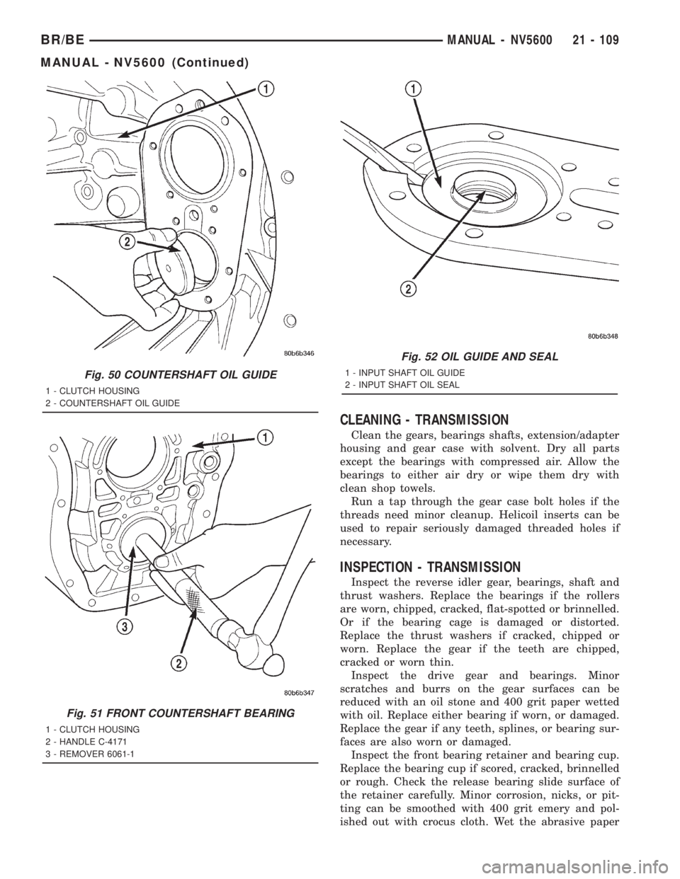
Fig. 50 COUNTERSHAFT OIL GUIDE
1 - CLUTCH HOUSING
2 - COUNTERSHAFT OIL GUIDE
Fig. 51 FRONT COUNTERSHAFT BEARING
1 - CLUTCH HOUSING
2 - HANDLE C-4171
3 - REMOVER 6061-1
Fig. 52 OIL GUIDE AND SEAL
1 - INPUT SHAFT OIL GUIDE
2 - INPUT SHAFT OIL SEAL
BR/BEMANUAL - NV5600 21 - 109
MANUAL - NV5600 (Continued)
Page 1745 of 2889
and crocus cloth with oil when smoothing/polishing.
Replace the retainer if worn or damaged in any way.
Do not reuse original retainer bolts. Install new bolts
during assembly.
Inspect the countershaft and bearings. Replace the
bearings if worn, rough, flat spotted or heat checked.
Check the countershaft gear teeth carefully. Small
nicks, scratches or burrs can be removed with an oil
stone and 400 grit paper wetted with oil. Replace the
shaft if any of the teeth are worn, cracked, broken or
severely chipped.
Be sure to check condition of the countershaft bear-
ing cups. Replace either bearings cup if worn, or
damaged.
Check condition of the mainshaft. Inspect all the
bearing surfaces, splines and threads. Also check con-
dition of the snap ring grooves in the hub area and
the speedometer drive gear teeth. Minor scratches or
burrs can be removed with an oil stone and polished
with crocus cloth. However, replace the shaft if any
surfaces exhibit considerable wear or damage.
Check condition of the gear case and extension or
adapter housing. Be sure the alignment dowels in the
case top surface and in the housing/adapter are tight
and in good condition.
Run a tap through the gear case bolt holes if the
threads need minor cleanup. Helicoil inserts can be
used to repair seriously damaged threaded holes if
necessary.
Be sure all case and housing/adapter sealing and
mating surfaces are free of burrs and nicks. This is
especially important as gaskets are not used in the
transmission. Minor nicks and scratches on the seal-
ing surfaces can be dressed off with a fine tooth file
or oil stone.
Replace the gear case or housing/adapter if cracked
or broken. Do not attempt to repair this type of dam-
age by welding or brazing.
Check condition of the countershaft fifth gear com-
ponents. This includes the shift lug and rail located
in the gear case and the rail bushings.
Inspect the gear and hub assembly. Minor burrs
can be cleaned up with an oil stone. However, the
gear and hub assembly should be replaced if the
teeth or splines are excessively worn, or damaged.
The synchro sleeve should also be replaced if worn or
damaged in any way. Do not reuse synchro struts
that are worn or springs that are collapsed or
severely distorted. Replace worn distorted synchro
parts to avoid shift problems after assembly and
installation.
The shift fork should be inspected for evidence of
wear and distortion. Check fit of the sleeve in the
fork to be sure the two parts fit and work smoothly.
Replace the fork if the roll pin holes are worn over-
size or damaged. Do not attempt to salvage a wornfork. It will cause shift problems later on. Replace
shift fork roll pins if necessary or if doubt exists
about their condition.
The bearings should be examined carefully for
wear, roughness, flat spots, pitting or other damage.
Replace the bearings if necessary.
Inspect the blocker ring and clutch gear. replace
either part if worn or damaged in any way. Also be
sure replacement parts fit properly before proceeding
with assembly.
Examine the 1-2 synchro hub and sleeve for wear
or damage. Replace sleeve and hub if the splines are
worn, chipped or damaged.
Replace the synchro struts if worn, or chipped. Also
replace the springs if collapsed, distorted or broken.
Inspect the mainshaft geartrain components.
Check teeth on all gears, hubs, clutch gears, stop
rings and clutch rings. The teeth must be in good
condition and not worn, cracked or chipped. Replace
any component that exhibits wear or damage.
Examine the synchro stop rings, clutch rings and
clutch gears. Replace any part that exhibits wear,
distortion or damage. Replace the clutch rings if the
friction material is burned, flaking off or worn.
Inspect all of the thrust washers and locating pins.
Replace the pins if bent or worn. Replace the wash-
ers if worn or the locating pin notches are distorted.
Check condition of the synchro struts and springs.
Replace these parts if worn, cracked or distorted.
ASSEMBLY
NOTE: Gaskets are not used in the transmission.
Use MoparTGasket Maker or equivalent on all gear
case and extension housing sealing surfaces.
OUTPUT SHAFT
(1) Place second gear on bench with the synchro
clutch ring up.
(2) Install second gear synchro inner blocker ring
onto second gear (Fig. 53).
(3) Install second gear synchro friction cone over
the blocker ring and onto second gear (Fig. 54).
(4) Install second gear synchro outer blocker ring
over the second gear synchro friction cone. Align one
of the lugs on the outer ring with a lug on the inner
ring (Fig. 55).
(5) Install 1-2 synchro assembly onto the second
gear assembly (Fig. 56).
(6) Reverse assembly on the bench.
21 - 110 MANUAL - NV5600BR/BE
MANUAL - NV5600 (Continued)
Page 1769 of 2889
AUTOMATIC TRANSMISSION - 42RE
TABLE OF CONTENTS
page page
AUTOMATIC TRANSMISSION - 42RE
DESCRIPTION..........................135
OPERATION............................137
DIAGNOSIS AND TESTING................143
AUTOMATIC TRANSMISSION.............143
PRELIMINARY........................143
ROAD TESTING.......................143
HYDRAULIC PRESSURE TEST...........144
AIR CHECKING TRANSMISSION CLUTCH
AND BAND OPERATION.................147
CONVERTER HOUSING FLUID LEAK......148
DIAGNOSIS CHARTS...................149
STANDARD PROCEDURE.................159
ALUMINUM THREAD REPAIR.............159
REMOVAL.............................159
DISASSEMBLY..........................160
CLEANING.............................165
INSPECTION...........................165
ASSEMBLY............................166
INSTALLATION..........................173
SCHEMATICS AND DIAGRAMS.............174
SPECIFICATIONS........................186
SPECIAL TOOLS........................188
ACCUMULATOR
DESCRIPTION..........................191
OPERATION............................191
INSPECTION...........................192
BANDS
DESCRIPTION..........................192
OPERATION............................192
ADJUSTMENTS.........................193
ELECTRONIC GOVERNOR
DESCRIPTION..........................194
OPERATION............................194
REMOVAL.............................196
INSTALLATION..........................197
EXTENSION HOUSING BUSHING
REMOVAL.............................198
INSTALLATION..........................198
EXTENSION HOUSING SEAL
REMOVAL.............................198
INSTALLATION..........................198
FLUID AND FILTER
DIAGNOSIS AND TESTING................199
EFFECTS OF INCORRECT FLUID LEVEL . . . 199
CAUSES OF BURNT FLUID..............199
FLUID CONTAMINATION................199
STANDARD PROCEDURE.................199
FLUID LEVEL CHECK...................199FLUID AND FILTER REPLACEMENT.......201
TRANSMISSION FILL...................201
FRONT CLUTCH
DESCRIPTION..........................202
OPERATION............................202
DISASSEMBLY..........................202
INSPECTION...........................205
ASSEMBLY............................206
FRONT SERVO
DESCRIPTION..........................206
OPERATION............................207
DISASSEMBLY..........................207
CLEANING.............................207
INSPECTION...........................207
ASSEMBLY............................208
OIL PUMP
DESCRIPTION..........................208
OPERATION............................208
STANDARD PROCEDURE.................209
OIL PUMP VOLUME CHECK..............209
DISASSEMBLY..........................209
CLEANING.............................211
INSPECTION...........................211
ASSEMBLY............................212
OUTPUT SHAFT FRONT BEARING
REMOVAL.............................213
INSTALLATION..........................213
OUTPUT SHAFT REAR BEARING
REMOVAL.............................213
INSTALLATION..........................213
OVERDRIVE CLUTCH
DESCRIPTION..........................214
OPERATION............................214
OVERDRIVE OFF SWITCH
DESCRIPTION..........................215
OPERATION............................215
DIAGNOSIS AND TESTING................215
OVERDRIVE ELECTRICAL CONTROLS.....215
REMOVAL.............................215
INSTALLATION..........................215
OVERDRIVE UNIT
REMOVAL.............................216
DISASSEMBLY..........................217
CLEANING.............................224
INSPECTION...........................224
ASSEMBLY............................225
INSTALLATION..........................234
21 - 134 AUTOMATIC TRANSMISSION - 42REBR/BE
Page 1778 of 2889
FOURTH GEAR POWERFLOW
Fourth gear overdrive range is electronically con-
trolled and hydraulically activated. Various sensor
inputs are supplied to the powertrain control module
to operate the overdrive solenoid on the valve body.
The solenoid contains a check ball that opens and
closes a vent port in the 3-4 shift valve feed passage.
The overdrive solenoid (and check ball) are not ener-
gized in first, second, third, or reverse gear. The vent
port remains open, diverting line pressure from the
2-3 shift valve away from the 3-4 shift valve. The
overdrive control switch must be in the ON position
to transmit overdrive status to the PCM. A 3-4
upshift occurs only when the overdrive solenoid is
energized by the PCM. The PCM energizes the over-
drive solenoid during the 3-4 upshift. This causes the
solenoid check ball to close the vent port allowing
line pressure from the 2-3 shift valve to act directly
on the 3-4 upshift valve. Line pressure on the 3-4
shift valve overcomes valve spring pressure moving
the valve to the upshift position. This action exposes
the feed passages to the 3-4 timing valve, 3-4 quick
fill valve, 3-4 accumulator, and ultimately to the
overdrive piston. Line pressure through the timing
valve moves the overdrive piston into contact with
the overdrive clutch. The direct clutch is disengaged
before the overdrive clutch is engaged. The boost
valve provides increased fluid apply pressure to the
overdrive clutch during 3-4 upshifts, and when accel-
erating in fourth gear. The 3-4 accumulator cushions
overdrive clutch engagement to smooth 3-4 upshifts.
The accumulator is charged at the same time as
apply pressure acts against the overdrive piston.
DIAGNOSIS AND TESTING - AUTOMATIC
TRANSMISSION
Automatic transmission problems can be a result of
poor engine performance, incorrect fluid level, incor-
rect linkage or cable adjustment, band or hydraulic
control pressure adjustments, hydraulic system mal-
functions or electrical/mechanical component mal-
functions. Begin diagnosis by checking the easily
accessible items such as: fluid level and condition,
linkage adjustments and electrical connections. A
road test will determine if further diagnosis is neces-
sary.
DIAGNOSIS AND TESTING - PRELIMINARY
Two basic procedures are required. One procedure
for vehicles that are drivable and an alternate proce-
dure for disabled vehicles (will not back up or move
forward).
VEHICLE IS DRIVEABLE
(1) Check for transmission fault codes using DRBt
scan tool.(2) Check fluid level and condition.
(3) Adjust throttle and gearshift linkage if com-
plaint was based on delayed, erratic, or harsh shifts.
(4) Road test and note how transmission upshifts,
downshifts, and engages.
(5) Perform hydraulic pressure test if shift prob-
lems were noted during road test.
(6) Perform air-pressure test to check clutch-band
operation.
VEHICLE IS DISABLED
(1) Check fluid level and condition.
(2) Check for broken or disconnected gearshift or
throttle linkage.
(3) Check for cracked, leaking cooler lines, or loose
or missing pressure-port plugs.
(4) Raise and support vehicle on safety stands,
start engine, shift transmission into gear, and note
following:
(a) If propeller shaft turns but wheels do not,
problem is with differential or axle shafts.
(b) If propeller shaft does not turn and transmis-
sion is noisy, stop engine. Remove oil pan, and
check for debris. If pan is clear, remove transmis-
sion and check for damaged drive plate, converter,
oil pump, or input shaft.
(c) If propeller shaft does not turn and transmis-
sion is not noisy, perform hydraulic-pressure test to
determine if problem is hydraulic or mechanical.
DIAGNOSIS AND TESTING - ROAD TESTING
Before road testing, be sure the fluid level and con-
trol cable adjustments have been checked and
adjusted if necessary. Verify that diagnostic trouble
codes have been resolved.
Observe engine performance during the road test.
A poorly tuned engine will not allow accurate analy-
sis of transmission operation.
Operate the transmission in all gear ranges. Check
for shift variations and engine flare which indicates
slippage. Note if shifts are harsh, spongy, delayed,
early, or if part throttle downshifts are sensitive.
Slippage indicated by engine flare, usually means
clutch, band or overrunning clutch problems. If the
condition is advanced, an overhaul will be necessary
to restore normal operation.
A slipping clutch or band can often be determined
by comparing which internal units are applied in the
various gear ranges. The Clutch and Band Applica-
tion chart provides a basis for analyzing road test
results.
BR/BEAUTOMATIC TRANSMISSION - 42RE 21 - 143
AUTOMATIC TRANSMISSION - 42RE (Continued)
Page 1782 of 2889
PRESSURE TEST ANALYSIS CHART
TEST CONDITION INDICATION
Line pressure OK during
any one testPump and regulator
valve OK
Line pressure OK in R
but low in D, 2, 1Leakage in rear clutch
area (seal rings, clutch
seals)
Pressure low in D Fourth
Gear RangeOverdrive clutch piston
seal, or check ball
problem
Pressure OK in 1, 2 but
low in D3 and RLeakage in front clutch
area
Pressure OK in 2 but low
in R and 1Leakage in rear servo
Front servo pressure in 2 Leakage in servo; broken
servo ring or cracked
servo piston
Pressure low in all
positionsClogged filter, stuck
regulator valve, worn or
faulty pump, low oil level
Governor pressure too
high at idle speedGovernor pressure
solenoid valve system
fault. Refer to diagnostic
book.
Governor pressure low at
all mph figuresFaulty governor pressure
solenoid, transmission
control module, or
governor pressure
sensor
Lubrication pressure low
at all throttle positionsClogged fluid cooler or
lines, seal rings leaking,
worn pump bushings,
pump, clutch retainer, or
clogged filter.
Line pressure high Output shaft plugged,
sticky regulator valve
Line pressure low Sticky regulator valve,
clogged filter, worn pump
DIAGNOSIS AND TESTING - AIR CHECKING
TRANSMISSION CLUTCH AND BAND
OPERATION
Air-pressure testing can be used to check transmis-
sion front/rear clutch and band operation. The test
can be conducted with the transmission either in the
vehicle or on the work bench, as a final check, after
overhaul.
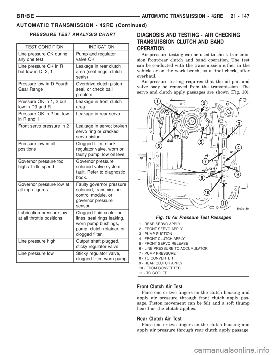
Air-pressure testing requires that the oil pan and
valve body be removed from the transmission. The
servo and clutch apply passages are shown (Fig. 10).
Front Clutch Air Test
Place one or two fingers on the clutch housing and
apply air pressure through front clutch apply pas-
sage. Piston movement can be felt and a soft thump
heard as the clutch applies.
Rear Clutch Air Test
Place one or two fingers on the clutch housing and
apply air pressure through rear clutch apply passage.
Fig. 10 Air Pressure Test Passages
1 - REAR SERVO APPLY
2 - FRONT SERVO APPLY
3 - PUMP SUCTION
4 - FRONT CLUTCH APPLY
5 - FRONT SERVO RELEASE
6 - LINE PRESSURE TO ACCUMULATOR
7 - PUMP PRESSURE
8 - TO CONVERTER
9 - REAR CLUTCH APPLY
10 - FROM CONVERTER
11 - TO COOLER
BR/BEAUTOMATIC TRANSMISSION - 42RE 21 - 147
AUTOMATIC TRANSMISSION - 42RE (Continued)