2001 DODGE RAM check oil
[x] Cancel search: check oilPage 1626 of 2889
(8) Fill the system with fluid and perform Steering
Pump Initial Operation, (Refer to 19 - STEERING/
PUMP - STANDARD PROCEDURE).
(9) Start the engine and run it for fifteen minutes
then stop the engine.
(10) Remove the return line/lines from the pump
and plug the pump port/ports.
(11) Pour fresh fluid into the reservoir and check
the draining fluid for contamination. If the fluid is
still contaminated, disassemble and clean the steer-
ing gear and flush the system again.
(12) Install the return line/lines and perform
Steering Pump Initial Operation, (Refer to 19 -
STEERING/PUMP - STANDARD PROCEDURE).
REMOVAL - GASOLINE ENGINE
(1) Remove the serpentine drive belt, (Refer to 7 -
COOLING/ACCESSORY DRIVE/DRIVE BELTS -
REMOVAL) OR (Refer to 7 - COOLING/ACCESSORY
DRIVE/DRIVE BELTS - REMOVAL).
(2) Remove the hoses from the power steering
pump and cap the fittings.
(3) Remove battery ground cable and unthread
stud from cylinder head, do not remove from bracket.
(4) Loosen upper bracket bolt and remove the
lower bracket to engine block bolts.
(5) Pivot the pump assembly past the coolant tube.
(6) Remove the upper stud and remove upper bolt
from cylinder head.
(7) Remove steering pump and mounting bracket
from engine as an assembly.
(8) Remove the pump pulley with Puller C-4333, to
access pump attaching bolts, (Refer to 19 - STEER-
ING/PUMP/PULLEY - REMOVAL).
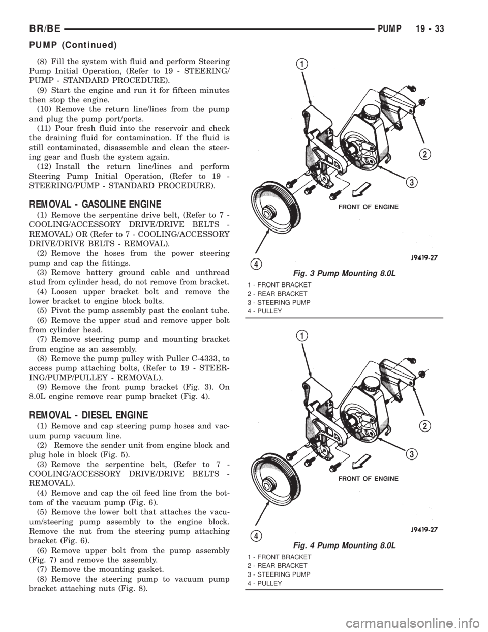
(9) Remove the front pump bracket (Fig. 3). On
8.0L engine remove rear pump bracket (Fig. 4).
REMOVAL - DIESEL ENGINE
(1) Remove and cap steering pump hoses and vac-
uum pump vacuum line.
(2) Remove the sender unit from engine block and
plug hole in block (Fig. 5).
(3) Remove the serpentine belt, (Refer to 7 -
COOLING/ACCESSORY DRIVE/DRIVE BELTS -
REMOVAL).
(4) Remove and cap the oil feed line from the bot-
tom of the vacuum pump (Fig. 6).
(5) Remove the lower bolt that attaches the vacu-
um/steering pump assembly to the engine block.
Remove the nut from the steering pump attaching
bracket (Fig. 6).
(6) Remove upper bolt from the pump assembly
(Fig. 7) and remove the assembly.
(7) Remove the mounting gasket.
(8) Remove the steering pump to vacuum pump
bracket attaching nuts (Fig. 8).
Fig. 3 Pump Mounting 8.0L
1 - FRONT BRACKET
2 - REAR BRACKET
3 - STEERING PUMP
4 - PULLEY
Fig. 4 Pump Mounting 8.0L
1 - FRONT BRACKET
2 - REAR BRACKET
3 - STEERING PUMP
4 - PULLEY
BR/BEPUMP 19 - 33
PUMP (Continued)
Page 1628 of 2889
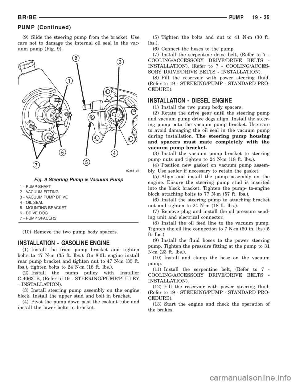
(9) Slide the steering pump from the bracket. Use
care not to damage the internal oil seal in the vac-
uum pump (Fig. 9).
(10) Remove the two pump body spacers.
INSTALLATION - GASOLINE ENGINE
(1) Install the front pump bracket and tighten
bolts to 47 N´m (35 ft. lbs.). On 8.0L engine install
rear pump bracket and tighten nut to 47 N´m (35 ft.
lbs.), tighten bolts to 24 N´m (18 ft. lbs.).
(2) Install the pump pulley with Installer
C-4063±B, (Refer to 19 - STEERING/PUMP/PULLEY
- INSTALLATION).
(3) Install steering pump assembly on the engine
block. Install the upper stud and bolt in bracket.
(4) Pivot the pump down past the coolant tube and
install the lower bolts in bracket.(5) Tighten the bolts and nut to 41 N´m (30 ft.
lbs.).
(6) Connect the hoses to the pump.
(7) Install the serpentine drive belt, (Refer to 7 -
COOLING/ACCESSORY DRIVE/DRIVE BELTS -
INSTALLATION), (Refer to 7 - COOLING/ACCES-
SORY DRIVE/DRIVE BELTS - INSTALLATION).
(8) Fill the reservoir with power steering fluid,
(Refer to 19 - STEERING/PUMP - STANDARD PRO-
CEDURE).
INSTALLATION - DIESEL ENGINE
(1) Install the two pump body spacers.
(2) Rotate the drive gear until the steering pump
and vacuum pump drive dogs align. Install the steer-
ing pump onto the vacuum pump bracket. Use care
to avoid damaging the oil seal in the vacuum pump
during installation.The steering pump housing
and spacers must mate completely with the
vacuum pump bracket.
(3) Install the vacuum pump bracket to steering
pump nuts and tighten to 24 N´m (18 ft. lbs.).
(4) Position new gasket on vacuum pump assem-
bly. Use sealer if necessary to retain the gasket.
(5) Align and install the pump assembly on the
engine. Ensure the steering pump stud is inserted
into the block bracket. Tighten the pump- to-engine
block attaching bolts to 77 N´m (57 ft. lbs.).
(6) Install the steering pump to attaching bracket
nut and tighten to 24 N´m (18 ft. lbs.).
(7) Remove plug and install the oil pressure send-
ing unit and electrical connector.
(8) Install the oil feed line to the vacuum pump.
Tighten the oil line connection to 7 N´m (60 in. lbs./ 5
ft. lbs.).
(9) Install the fluid hoses to the power steering
pump. Tighten the pressure fitting at the pump to 31
N´m (23 ft. lbs.).
(10) Install and clamp the hose on the vacuum
pump.
(11) Install the serpentine belt, (Refer to 7 -
COOLING/ACCESSORY DRIVE/DRIVE BELTS -
INSTALLATION).
(12) Fill the reservoir with power steering fluid,
(Refer to 19 - STEERING/PUMP - STANDARD PRO-
CEDURE).
(13) Start the engine and check the operation of
the brakes.
Fig. 9 Steering Pump & Vacuum Pump
1 - PUMP SHAFT
2 - VACUUM FITTING
3 - VACUUM PUMP DRIVE
4 - OIL SEAL
5 - MOUNTING BRACKET
6 - DRIVE DOG
7 - PUMP SPACERS
BR/BEPUMP 19 - 35
PUMP (Continued)
Page 1638 of 2889
The driver selects a particular gear by moving the
shift lever to the desired gear position. This move-
ment moves the internal transmission shift compo-
nents to begin the shift sequence. As the shift lever
moves the selected shift rail, the shift fork attached
to that rail begins to move. The fork is positioned in
a groove in the outer circumference of the synchro-
nizer sleeve. As the shift fork moves the synchronizer
sleeve, the synchronizer begins to speed-up or slow
down the selected gear (depending on whether we are
up-shifting or down-shifting). The synchronizer does
this by having the synchronizer hub splined to the
mainshaft, or the countershaft in some cases, and
moving the blocker ring into contact with the gear's
friction cone. As the blocker ring and friction cone
come together, the gear speed is brought up or down
to the speed of the synchronizer. As the two speeds
match, the splines on the inside of the synchronizer
sleeve become aligned with the teeth on the blocker
ring and the friction cone and eventually will slide
over the teeth, locking the gear to the mainshaft, or
countershaft, through the synchronizer.
DIAGNOSIS AND TESTING - MANUAL
TRANSMISSION
LOW LUBRICANT LEVEL
A low transmission lubricant level is generally the
result of a leak, inadequate lubricant fill or an incor-
rect lubricant level check.
Leaks can occur at the mating surfaces of the gear
case, adaptor or extension housing, or from the front/
rear seals. A suspected leak could also be the result
of an overfill condition.
Leaks at the rear of the extension or adapter hous-
ing will be from the housing oil seals. Leaks at com-
ponent mating surfaces will probably be the result of
inadequate sealer, gaps in the sealer, incorrect bolt
tightening or use of a non-recommended sealer.
A leak at the front of the transmission will be from
either the front bearing retainer or retainer seal.
Lubricant may be seen dripping from the clutch
housing after extended operation. If the leak is
severe, it may also contaminate the clutch disc caus-
ing the disc to slip, grab and or chatter.
A correct lubricant level check can only be made
when the vehicle is level. Also allow the lubricant to
settle for a minute or so before checking. These rec-
ommendations will ensure an accurate check and
avoid an underfill or overfill condition. Always check
the lubricant level after any addition of fluid to avoid
an incorrect lubricant level condition.
HARD SHIFTING
Hard shifting is usually caused by a low lubricant
level, improper or contaminated lubricants. The con-sequence of using non-recommended lubricants is
noise, excessive wear, internal bind and hard shift-
ing. Substantial lubricant leaks can result in gear,
shift rail, synchro, and bearing damage. If a leak
goes undetected for an extended period, the first indi-
cations of component damage are usually hard shift-
ing and noise.
Component damage, incorrect clutch adjustment or
damaged clutch pressure plate or disc are additional
probable causes of increased shift effort. Incorrect
adjustment or a worn/damaged pressure plate or disc
can cause incorrect release. If clutch problem is
advanced, gear clash during shifts can result. Worn
or damaged synchro rings can cause gear clash when
shifting into any forward gear. In some new or
rebuilt transmissions, new synchro rings may tend to
stick slightly causing hard or noisy shifts. In most
cases this condition will decline as the rings wear-in.
TRANSMISSION NOISE
Most manual transmissions make some noise dur-
ing normal operation. Rotating gears generate a mild
whine that is audible, but generally only at extreme
speeds.
Severe highly audible transmission noise is gener-
ally the initial indicator of a lubricant problem.
Insufficient, improper or contaminated lubricant will
promote rapid wear of gears, synchros, shift rails,
forks and bearings. The overheating caused by a
lubricant problem, can also lead to gear breakage.
REMOVAL
(1) Disconnect battery negative cable.
(2) Shift transmission into Neutral.
(3) Remove shift boot bezel screws and slide boot
upward on shift lever extension.
(4) Remove shift lever extension from the shift
tower and lever assembly.
(5) Remove bolts attaching shift tower and lever
assembly to rear case. Then remove shift tower and
lever assembly.
(6) Raise vehicle on hoist.
(7) Remove crankshaft position sensor. Retain sen-
sor attaching bolts.
(8) Remove skid plate, if equipped.
(9) Drain transmission lubricant if transmission
will be disassembled for service.
(10) Mark propeller shaft/shafts and yoke/yokes for
installation reference and remove propeller shaft/
shafts.
(11) Disengage harness from clips on transmission
housing.
(12) Support engine with adjustable jack stand
and wood block.
(13) Drain transmission lubricant if transmission
will be disassembled for service.
BR/BEMANUAL - NV3500 21 - 3
MANUAL - NV3500 (Continued)
Page 1650 of 2889
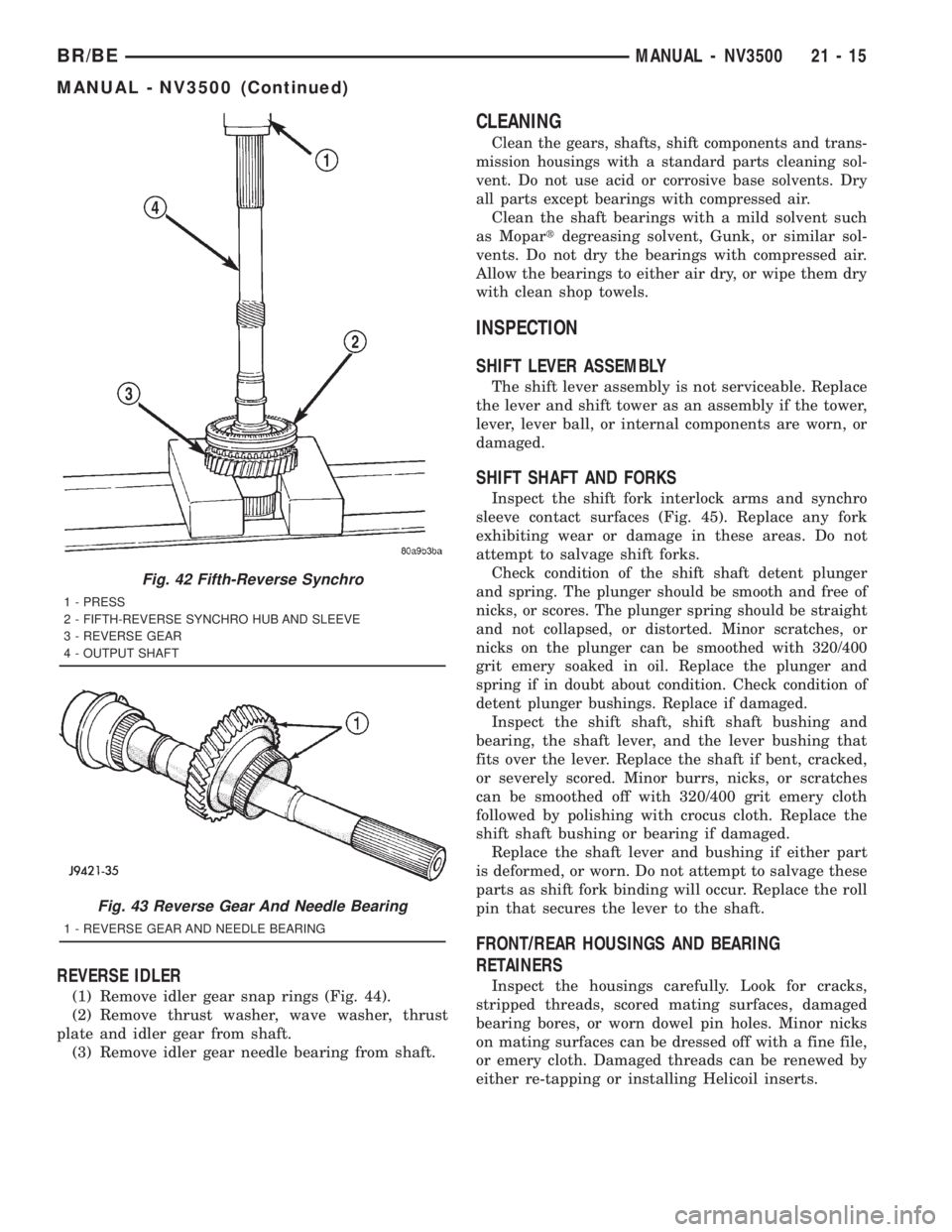
REVERSE IDLER
(1) Remove idler gear snap rings (Fig. 44).
(2) Remove thrust washer, wave washer, thrust
plate and idler gear from shaft.
(3) Remove idler gear needle bearing from shaft.
CLEANING
Clean the gears, shafts, shift components and trans-
mission housings with a standard parts cleaning sol-
vent. Do not use acid or corrosive base solvents. Dry
all parts except bearings with compressed air.
Clean the shaft bearings with a mild solvent such
as Mopartdegreasing solvent, Gunk, or similar sol-
vents. Do not dry the bearings with compressed air.
Allow the bearings to either air dry, or wipe them dry
with clean shop towels.
INSPECTION
SHIFT LEVER ASSEMBLY
The shift lever assembly is not serviceable. Replace
the lever and shift tower as an assembly if the tower,
lever, lever ball, or internal components are worn, or
damaged.
SHIFT SHAFT AND FORKS
Inspect the shift fork interlock arms and synchro
sleeve contact surfaces (Fig. 45). Replace any fork
exhibiting wear or damage in these areas. Do not
attempt to salvage shift forks.
Check condition of the shift shaft detent plunger
and spring. The plunger should be smooth and free of
nicks, or scores. The plunger spring should be straight
and not collapsed, or distorted. Minor scratches, or
nicks on the plunger can be smoothed with 320/400
grit emery soaked in oil. Replace the plunger and
spring if in doubt about condition. Check condition of
detent plunger bushings. Replace if damaged.
Inspect the shift shaft, shift shaft bushing and
bearing, the shaft lever, and the lever bushing that
fits over the lever. Replace the shaft if bent, cracked,
or severely scored. Minor burrs, nicks, or scratches
can be smoothed off with 320/400 grit emery cloth
followed by polishing with crocus cloth. Replace the
shift shaft bushing or bearing if damaged.
Replace the shaft lever and bushing if either part
is deformed, or worn. Do not attempt to salvage these
parts as shift fork binding will occur. Replace the roll
pin that secures the lever to the shaft.
FRONT/REAR HOUSINGS AND BEARING
RETAINERS
Inspect the housings carefully. Look for cracks,
stripped threads, scored mating surfaces, damaged
bearing bores, or worn dowel pin holes. Minor nicks
on mating surfaces can be dressed off with a fine file,
or emery cloth. Damaged threads can be renewed by
either re-tapping or installing Helicoil inserts.
Fig. 42 Fifth-Reverse Synchro
1 - PRESS
2 - FIFTH-REVERSE SYNCHRO HUB AND SLEEVE
3 - REVERSE GEAR
4 - OUTPUT SHAFT
Fig. 43 Reverse Gear And Needle Bearing
1 - REVERSE GEAR AND NEEDLE BEARING
BR/BEMANUAL - NV3500 21 - 15
MANUAL - NV3500 (Continued)
Page 1652 of 2889
Inspect the input shaft bearing retainer. Be sure
the release bearing slide surface of the retainer is in
good condition. Minor nicks on the surface can be
smoothed off with 320/420 grit emery cloth and final
polished with oil coated crocus cloth. Replace the
retainer seal if necessary.
Inspect the output shaft bearing retainer. Be sure
the U-shaped retainer is flat and free of distortion.
Replace the retainer if the threads are damaged, or if
the retainer is bent, or cracked.
COUNTERSHAFT BEARINGS AND RACES
The countershaft bearings and races are machine
lapped during manufacture to form matched sets.
The bearings and races should not be interchanged.
NOTE: The bearing races are a permanent press fit
in the housings and are NOT serviceable. If a bear-
ing race becomes damaged, it will be necessary to
replace the front or rear housing as necessary. A
new countershaft bearing will be supplied with each
new housing for service use.
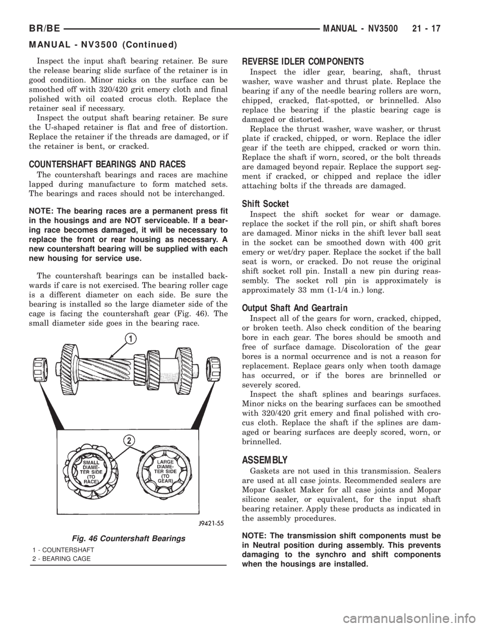
The countershaft bearings can be installed back-
wards if care is not exercised. The bearing roller cage
is a different diameter on each side. Be sure the
bearing is installed so the large diameter side of the
cage is facing the countershaft gear (Fig. 46). The
small diameter side goes in the bearing race.
REVERSE IDLER COMPONENTS
Inspect the idler gear, bearing, shaft, thrust
washer, wave washer and thrust plate. Replace the
bearing if any of the needle bearing rollers are worn,
chipped, cracked, flat-spotted, or brinnelled. Also
replace the bearing if the plastic bearing cage is
damaged or distorted.
Replace the thrust washer, wave washer, or thrust
plate if cracked, chipped, or worn. Replace the idler
gear if the teeth are chipped, cracked or worn thin.
Replace the shaft if worn, scored, or the bolt threads
are damaged beyond repair. Replace the support seg-
ment if cracked, or chipped and replace the idler
attaching bolts if the threads are damaged.
Shift Socket
Inspect the shift socket for wear or damage.
replace the socket if the roll pin, or shift shaft bores
are damaged. Minor nicks in the shift lever ball seat
in the socket can be smoothed down with 400 grit
emery or wet/dry paper. Replace the socket if the ball
seat is worn, or cracked. Do not reuse the original
shift socket roll pin. Install a new pin during reas-
sembly. The socket roll pin is approximately is
approximately 33 mm (1-1/4 in.) long.
Output Shaft And Geartrain
Inspect all of the gears for worn, cracked, chipped,
or broken teeth. Also check condition of the bearing
bore in each gear. The bores should be smooth and
free of surface damage. Discoloration of the gear
bores is a normal occurrence and is not a reason for
replacement. Replace gears only when tooth damage
has occurred, or if the bores are brinnelled or
severely scored.
Inspect the shaft splines and bearings surfaces.
Minor nicks on the bearing surfaces can be smoothed
with 320/420 grit emery and final polished with cro-
cus cloth. Replace the shaft if the splines are dam-
aged or bearing surfaces are deeply scored, worn, or
brinnelled.
ASSEMBLY
Gaskets are not used in this transmission. Sealers
are used at all case joints. Recommended sealers are
Mopar Gasket Maker for all case joints and Mopar
silicone sealer, or equivalent, for the input shaft
bearing retainer. Apply these products as indicated in
the assembly procedures.
NOTE: The transmission shift components must be
in Neutral position during assembly. This prevents
damaging to the synchro and shift components
when the housings are installed.
Fig. 46 Countershaft Bearings
1 - COUNTERSHAFT
2 - BEARING CAGE
BR/BEMANUAL - NV3500 21 - 17
MANUAL - NV3500 (Continued)
Page 1675 of 2889
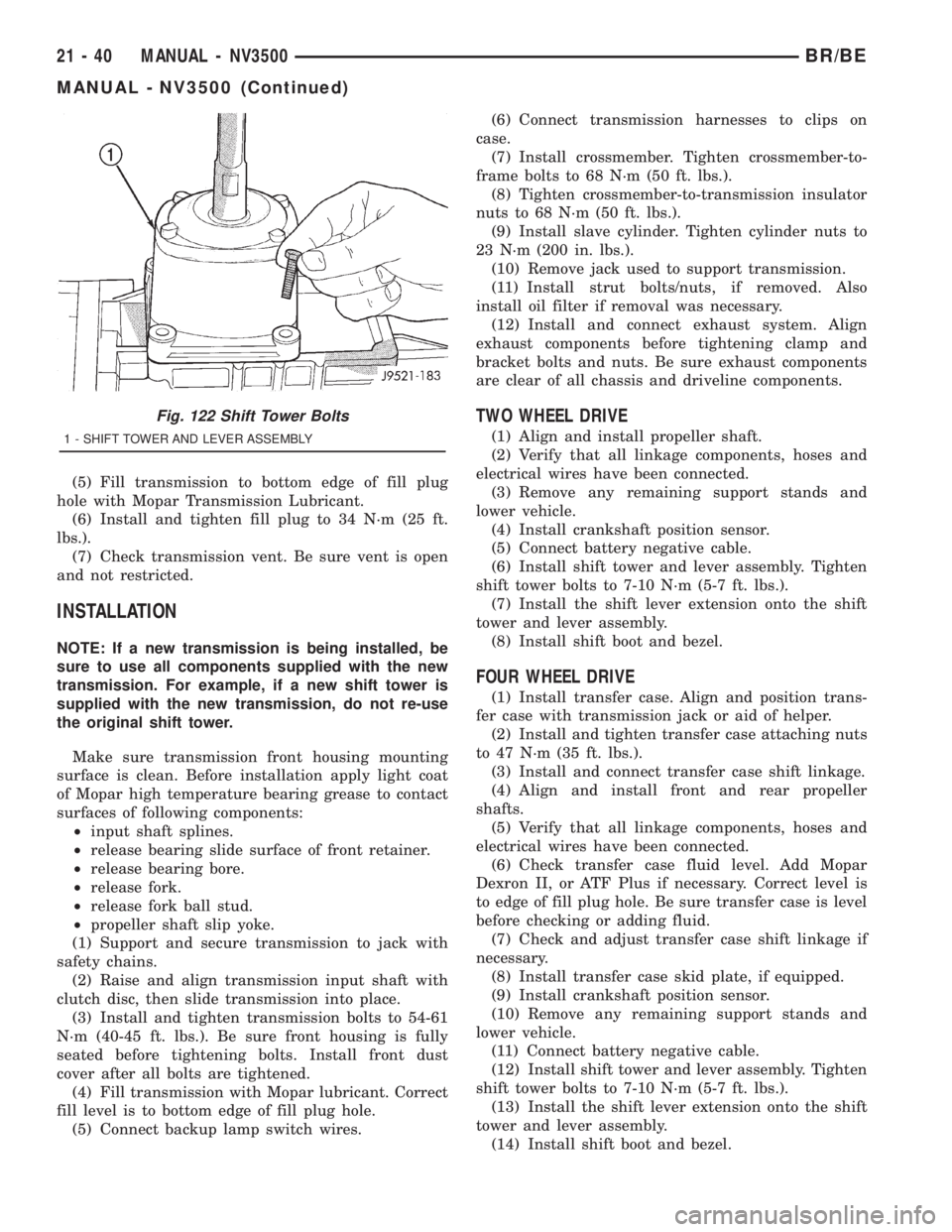
(5) Fill transmission to bottom edge of fill plug
hole with Mopar Transmission Lubricant.
(6) Install and tighten fill plug to 34 N´m (25 ft.
lbs.).
(7) Check transmission vent. Be sure vent is open
and not restricted.
INSTALLATION
NOTE: If a new transmission is being installed, be
sure to use all components supplied with the new
transmission. For example, if a new shift tower is
supplied with the new transmission, do not re-use
the original shift tower.
Make sure transmission front housing mounting
surface is clean. Before installation apply light coat
of Mopar high temperature bearing grease to contact
surfaces of following components:
²input shaft splines.
²release bearing slide surface of front retainer.
²release bearing bore.
²release fork.
²release fork ball stud.
²propeller shaft slip yoke.
(1) Support and secure transmission to jack with
safety chains.
(2) Raise and align transmission input shaft with
clutch disc, then slide transmission into place.
(3) Install and tighten transmission bolts to 54-61
N´m (40-45 ft. lbs.). Be sure front housing is fully
seated before tightening bolts. Install front dust
cover after all bolts are tightened.
(4) Fill transmission with Mopar lubricant. Correct
fill level is to bottom edge of fill plug hole.
(5) Connect backup lamp switch wires.(6) Connect transmission harnesses to clips on
case.
(7) Install crossmember. Tighten crossmember-to-
frame bolts to 68 N´m (50 ft. lbs.).
(8) Tighten crossmember-to-transmission insulator
nuts to 68 N´m (50 ft. lbs.).
(9) Install slave cylinder. Tighten cylinder nuts to
23 N´m (200 in. lbs.).
(10) Remove jack used to support transmission.
(11) Install strut bolts/nuts, if removed. Also
install oil filter if removal was necessary.
(12) Install and connect exhaust system. Align
exhaust components before tightening clamp and
bracket bolts and nuts. Be sure exhaust components
are clear of all chassis and driveline components.
TWO WHEEL DRIVE
(1) Align and install propeller shaft.
(2) Verify that all linkage components, hoses and
electrical wires have been connected.
(3) Remove any remaining support stands and
lower vehicle.
(4) Install crankshaft position sensor.
(5) Connect battery negative cable.
(6) Install shift tower and lever assembly. Tighten
shift tower bolts to 7-10 N´m (5-7 ft. lbs.).
(7) Install the shift lever extension onto the shift
tower and lever assembly.
(8) Install shift boot and bezel.
FOUR WHEEL DRIVE
(1) Install transfer case. Align and position trans-
fer case with transmission jack or aid of helper.
(2) Install and tighten transfer case attaching nuts
to 47 N´m (35 ft. lbs.).
(3) Install and connect transfer case shift linkage.
(4) Align and install front and rear propeller
shafts.
(5) Verify that all linkage components, hoses and
electrical wires have been connected.
(6) Check transfer case fluid level. Add Mopar
Dexron II, or ATF Plus if necessary. Correct level is
to edge of fill plug hole. Be sure transfer case is level
before checking or adding fluid.
(7) Check and adjust transfer case shift linkage if
necessary.
(8) Install transfer case skid plate, if equipped.
(9) Install crankshaft position sensor.
(10) Remove any remaining support stands and
lower vehicle.
(11) Connect battery negative cable.
(12) Install shift tower and lever assembly. Tighten
shift tower bolts to 7-10 N´m (5-7 ft. lbs.).
(13) Install the shift lever extension onto the shift
tower and lever assembly.
(14) Install shift boot and bezel.
Fig. 122 Shift Tower Bolts
1 - SHIFT TOWER AND LEVER ASSEMBLY
21 - 40 MANUAL - NV3500BR/BE
MANUAL - NV3500 (Continued)
Page 1681 of 2889
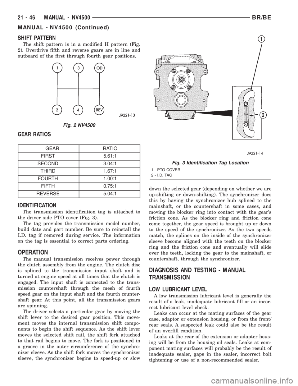
SHIFT PATTERN
The shift pattern is in a modified H pattern (Fig.
2). Overdrive fifth and reverse gears are in line and
outboard of the first through fourth gear positions.
GEAR RATIOS
GEAR RATIO
FIRST 5.61:1
SECOND 3.04:1
THIRD 1.67:1
FOURTH 1.00:1
FIFTH 0.75:1
REVERSE 5.04:1
IDENTIFICATION
The transmission identification tag is attached to
the driver side PTO cover (Fig. 3).
The tag provides the transmission model number,
build date and part number. Be sure to reinstall the
I.D. tag if removed during service. The information
on the tag is essential to correct parts ordering.
OPERATION
The manual transmission receives power through
the clutch assembly from the engine. The clutch disc
is splined to the transmission input shaft and is
turned at engine speed at all times that the clutch is
engaged. The input shaft is connected to the trans-
mission countershaft through the mesh of fourth
speed gear on the input shaft and the fourth counter-
shaft gear. At this point, all the transmission gears
are spinning.
The driver selects a particular gear by moving the
shift lever to the desired gear position. This move-
ment moves the internal transmission shift compo-
nents to begin the shift sequence. As the shift lever
moves the selected shift rail, the shift fork attached
to that rail begins to move. The fork is positioned in
a groove in the outer circumference of the synchro-
nizer sleeve. As the shift fork moves the synchronizer
sleeve, the synchronizer begins to speed-up or slowdown the selected gear (depending on whether we are
up-shifting or down-shifting). The synchronizer does
this by having the synchronizer hub splined to the
mainshaft, or the countershaft in some cases, and
moving the blocker ring into contact with the gear's
friction cone. As the blocker ring and friction cone
come together, the gear speed is brought up or down
to the speed of the synchronizer. As the two speeds
match, the splines on the inside of the synchronizer
sleeve become aligned with the teeth on the blocker
ring and the friction cone and eventually will slide
over the teeth, locking the gear to the mainshaft, or
countershaft, through the synchronizer.
DIAGNOSIS AND TESTING - MANUAL
TRANSMISSION
LOW LUBRICANT LEVEL
A low transmission lubricant level is generally the
result of a leak, inadequate lubricant fill or an incor-
rect lubricant level check.
Leaks can occur at the mating surfaces of the gear
case, adaptor or extension housing, or from the front/
rear seals. A suspected leak could also be the result
of an overfill condition.
Leaks at the rear of the extension or adapter hous-
ing will be from the housing oil seals. Leaks at com-
ponent mating surfaces will probably be the result of
inadequate sealer, gaps in the sealer, incorrect bolt
tightening or use of a non-recommended sealer.
Fig. 2 NV4500
Fig. 3 Identification Tag Location
1 - PTO COVER
2 - I.D. TAG
21 - 46 MANUAL - NV4500BR/BE
MANUAL - NV4500 (Continued)
Page 1699 of 2889
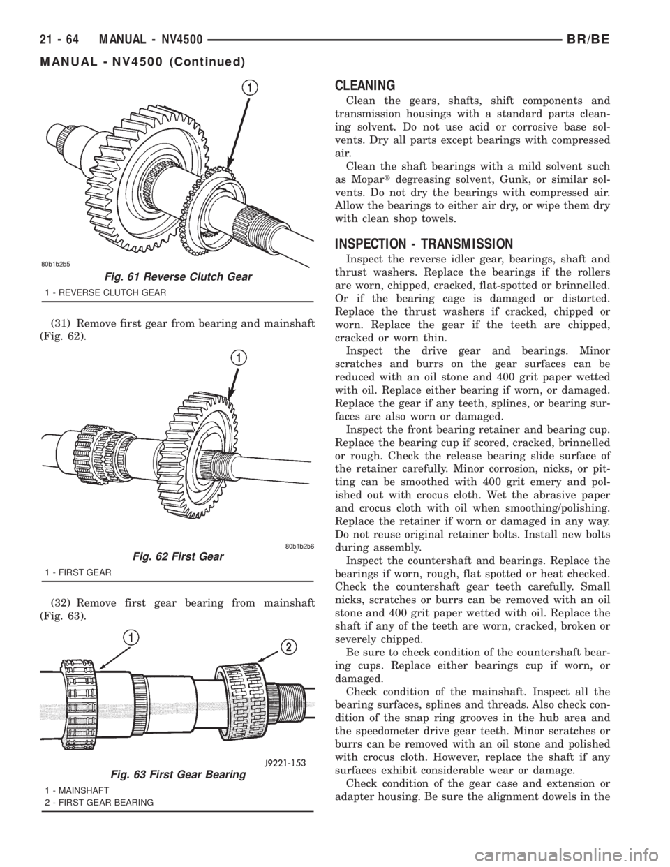
(31) Remove first gear from bearing and mainshaft
(Fig. 62).
(32) Remove first gear bearing from mainshaft
(Fig. 63).
CLEANING
Clean the gears, shafts, shift components and
transmission housings with a standard parts clean-
ing solvent. Do not use acid or corrosive base sol-
vents. Dry all parts except bearings with compressed
air.
Clean the shaft bearings with a mild solvent such
as Mopartdegreasing solvent, Gunk, or similar sol-
vents. Do not dry the bearings with compressed air.
Allow the bearings to either air dry, or wipe them dry
with clean shop towels.
INSPECTION - TRANSMISSION
Inspect the reverse idler gear, bearings, shaft and
thrust washers. Replace the bearings if the rollers
are worn, chipped, cracked, flat-spotted or brinnelled.
Or if the bearing cage is damaged or distorted.
Replace the thrust washers if cracked, chipped or
worn. Replace the gear if the teeth are chipped,
cracked or worn thin.
Inspect the drive gear and bearings. Minor
scratches and burrs on the gear surfaces can be
reduced with an oil stone and 400 grit paper wetted
with oil. Replace either bearing if worn, or damaged.
Replace the gear if any teeth, splines, or bearing sur-
faces are also worn or damaged.
Inspect the front bearing retainer and bearing cup.
Replace the bearing cup if scored, cracked, brinnelled
or rough. Check the release bearing slide surface of
the retainer carefully. Minor corrosion, nicks, or pit-
ting can be smoothed with 400 grit emery and pol-
ished out with crocus cloth. Wet the abrasive paper
and crocus cloth with oil when smoothing/polishing.
Replace the retainer if worn or damaged in any way.
Do not reuse original retainer bolts. Install new bolts
during assembly.
Inspect the countershaft and bearings. Replace the
bearings if worn, rough, flat spotted or heat checked.
Check the countershaft gear teeth carefully. Small
nicks, scratches or burrs can be removed with an oil
stone and 400 grit paper wetted with oil. Replace the
shaft if any of the teeth are worn, cracked, broken or
severely chipped.
Be sure to check condition of the countershaft bear-
ing cups. Replace either bearings cup if worn, or
damaged.
Check condition of the mainshaft. Inspect all the
bearing surfaces, splines and threads. Also check con-
dition of the snap ring grooves in the hub area and
the speedometer drive gear teeth. Minor scratches or
burrs can be removed with an oil stone and polished
with crocus cloth. However, replace the shaft if any
surfaces exhibit considerable wear or damage.
Check condition of the gear case and extension or
adapter housing. Be sure the alignment dowels in the
Fig. 61 Reverse Clutch Gear
1 - REVERSE CLUTCH GEAR
Fig. 62 First Gear
1 - FIRST GEAR
Fig. 63 First Gear Bearing
1 - MAINSHAFT
2 - FIRST GEAR BEARING
21 - 64 MANUAL - NV4500BR/BE
MANUAL - NV4500 (Continued)