2001 DODGE RAM check oil
[x] Cancel search: check oilPage 1555 of 2889
(1) Remove hose clamp and crankcase vent hose at
crankcase breather (Fig. 17). Remove crankcase
breather from gear cover. Breather threads into
cover.
(2) Remove injection pump nut and washer (Fig.
18). Locate keyway behind washer.
(3) Be sure keyway aligning fuel injection pump
shaft to injection pump gear is in proper position and
pump gear has not slipped on pump shaft.
The following steps will require removing timing
gear cover to gain access to timing gears. Refer to
Group 9, Engines for procedures.
(4) Use a T-type puller to separate injection pump
gear from pump shaft.
(5) Be sure keyway has been installed with arrow
pointed torearof pump (Fig. 19).
(6)Pump timing has been calibrated to pump
keyway. Be sure 3±digit number on pump key-
way (Fig. 19) matches 3±digit number on fuel
injection pump data plate. Plate is located on
side of injection pump (Fig. 20). Twenty±one dif-
ferent calibrated keyways/pumps are available.
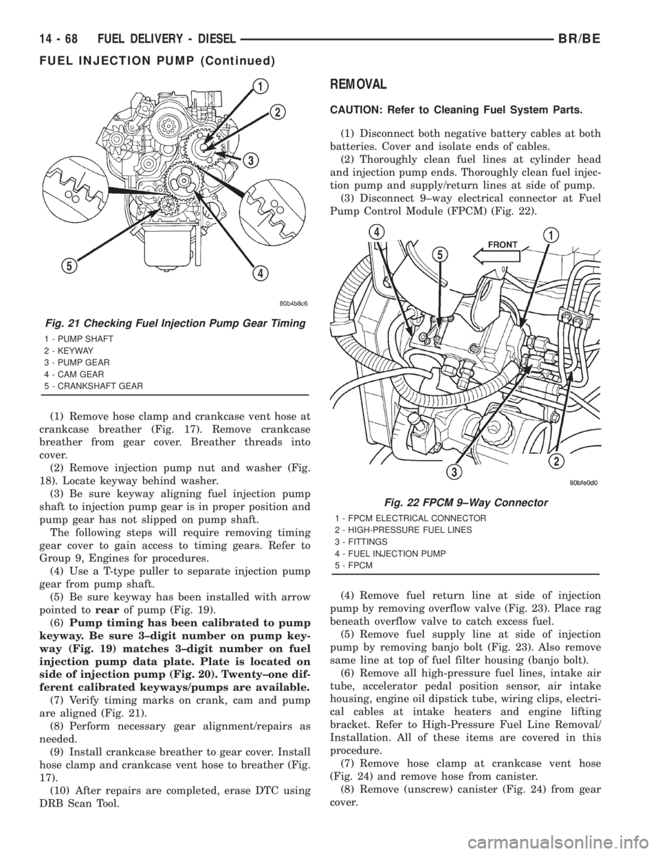
(7) Verify timing marks on crank, cam and pump
are aligned (Fig. 21).
(8) Perform necessary gear alignment/repairs as
needed.
(9) Install crankcase breather to gear cover. Install
hose clamp and crankcase vent hose to breather (Fig.
17).
(10) After repairs are completed, erase DTC using
DRB Scan Tool.
REMOVAL
CAUTION: Refer to Cleaning Fuel System Parts.
(1) Disconnect both negative battery cables at both
batteries. Cover and isolate ends of cables.
(2) Thoroughly clean fuel lines at cylinder head
and injection pump ends. Thoroughly clean fuel injec-
tion pump and supply/return lines at side of pump.
(3) Disconnect 9±way electrical connector at Fuel
Pump Control Module (FPCM) (Fig. 22).
(4) Remove fuel return line at side of injection
pump by removing overflow valve (Fig. 23). Place rag
beneath overflow valve to catch excess fuel.
(5) Remove fuel supply line at side of injection
pump by removing banjo bolt (Fig. 23). Also remove
same line at top of fuel filter housing (banjo bolt).
(6) Remove all high-pressure fuel lines, intake air
tube, accelerator pedal position sensor, air intake
housing, engine oil dipstick tube, wiring clips, electri-
cal cables at intake heaters and engine lifting
bracket. Refer to High-Pressure Fuel Line Removal/
Installation. All of these items are covered in this
procedure.
(7) Remove hose clamp at crankcase vent hose
(Fig. 24) and remove hose from canister.
(8) Remove (unscrew) canister (Fig. 24) from gear
cover.
Fig. 21 Checking Fuel Injection Pump Gear Timing
1 - PUMP SHAFT
2 - KEYWAY
3 - PUMP GEAR
4 - CAM GEAR
5 - CRANKSHAFT GEAR
Fig. 22 FPCM 9±Way Connector
1 - FPCM ELECTRICAL CONNECTOR
2 - HIGH-PRESSURE FUEL LINES
3 - FITTINGS
4 - FUEL INJECTION PUMP
5 - FPCM
14 - 68 FUEL DELIVERY - DIESELBR/BE
FUEL INJECTION PUMP (Continued)
Page 1560 of 2889
(15) Connect 9±way electrical connector to Fuel
Pump Control Module (FPCM) (Fig. 22).
(16) Connect both negative battery cables to both
batteries.
(17) Bleed air from fuel system.(Refer to 14 -
FUEL SYSTEM/FUEL DELIVERY - STANDARD
PROCEDURE).
(18) Check system for fuel or engine oil leaks.
FUEL INJECTION PUMP DATA
PLATE
SPECIFICATIONS
FUEL INJECTION PUMP DATA PLATE
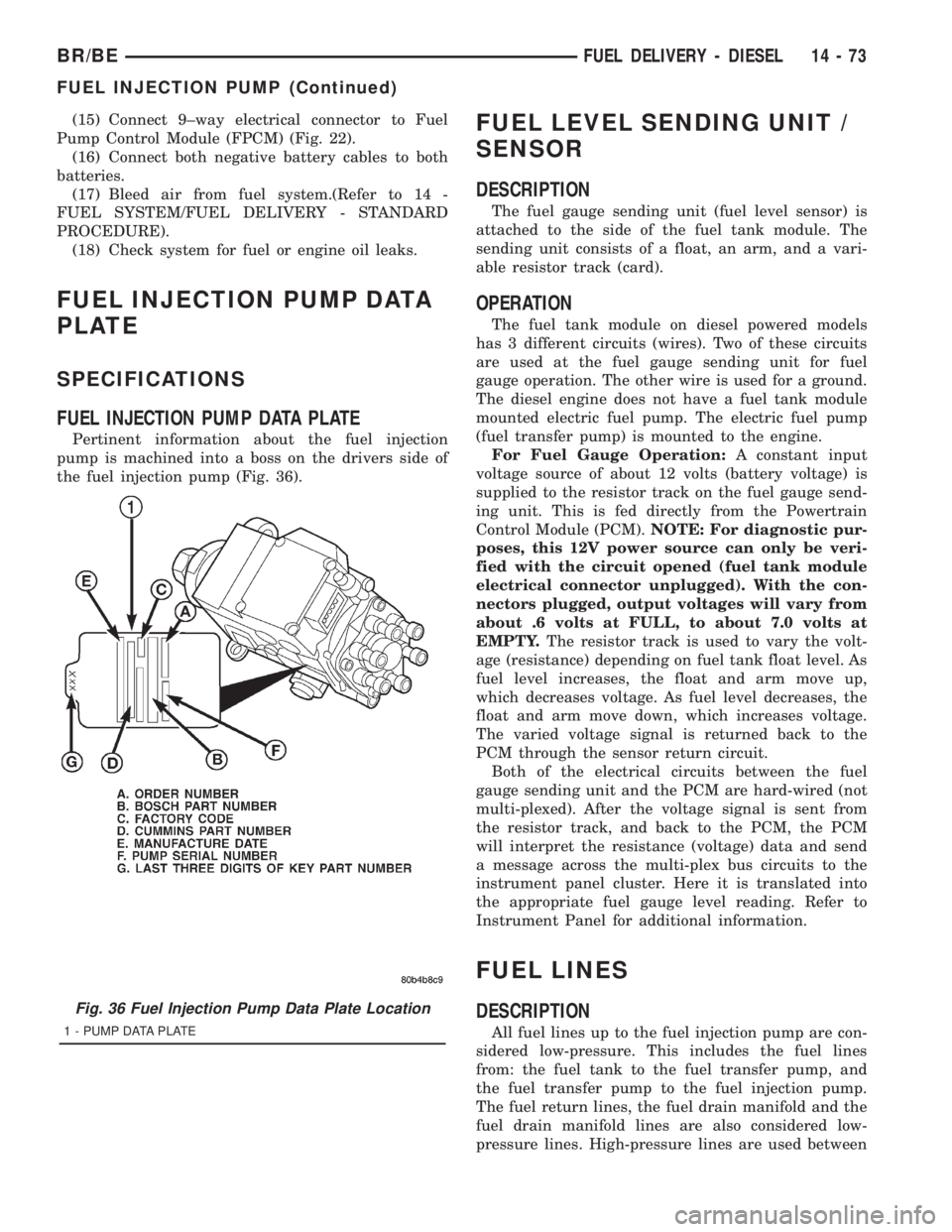
Pertinent information about the fuel injection
pump is machined into a boss on the drivers side of
the fuel injection pump (Fig. 36).
FUEL LEVEL SENDING UNIT /
SENSOR
DESCRIPTION
The fuel gauge sending unit (fuel level sensor) is
attached to the side of the fuel tank module. The
sending unit consists of a float, an arm, and a vari-
able resistor track (card).
OPERATION
The fuel tank module on diesel powered models
has 3 different circuits (wires). Two of these circuits
are used at the fuel gauge sending unit for fuel
gauge operation. The other wire is used for a ground.
The diesel engine does not have a fuel tank module
mounted electric fuel pump. The electric fuel pump
(fuel transfer pump) is mounted to the engine.
For Fuel Gauge Operation:A constant input
voltage source of about 12 volts (battery voltage) is
supplied to the resistor track on the fuel gauge send-
ing unit. This is fed directly from the Powertrain
Control Module (PCM).NOTE: For diagnostic pur-
poses, this 12V power source can only be veri-
fied with the circuit opened (fuel tank module
electrical connector unplugged). With the con-
nectors plugged, output voltages will vary from
about .6 volts at FULL, to about 7.0 volts at
EMPTY.The resistor track is used to vary the volt-
age (resistance) depending on fuel tank float level. As
fuel level increases, the float and arm move up,
which decreases voltage. As fuel level decreases, the
float and arm move down, which increases voltage.
The varied voltage signal is returned back to the
PCM through the sensor return circuit.
Both of the electrical circuits between the fuel
gauge sending unit and the PCM are hard-wired (not
multi-plexed). After the voltage signal is sent from
the resistor track, and back to the PCM, the PCM
will interpret the resistance (voltage) data and send
a message across the multi-plex bus circuits to the
instrument panel cluster. Here it is translated into
the appropriate fuel gauge level reading. Refer to
Instrument Panel for additional information.
FUEL LINES
DESCRIPTION
All fuel lines up to the fuel injection pump are con-
sidered low-pressure. This includes the fuel lines
from: the fuel tank to the fuel transfer pump, and
the fuel transfer pump to the fuel injection pump.
The fuel return lines, the fuel drain manifold and the
fuel drain manifold lines are also considered low-
pressure lines. High-pressure lines are used between
Fig. 36 Fuel Injection Pump Data Plate Location
1 - PUMP DATA PLATE
BR/BEFUEL DELIVERY - DIESEL 14 - 73
FUEL INJECTION PUMP (Continued)
Page 1565 of 2889
(3) Installrearinjection line bundle beginning
with cylinder head (fuel injector) connections, fol-
lowed by injection pump connections. Tighten all fit-
tings finger tight.
(4) Tighten fittings at fuel injector ends for cylin-
ders number 6 and 5 to 38 N´m (28 ft. lbs.) torque.
Do not tighten number 3 line at this time. It
will be tightened during bleeding procedure.
(5) Tighten 3 fittings at fuel injection pump ends
to 24 N´m (18 ft. lbs.) torque.
(6) Installfrontinjection line bundle beginning
with cylinder head (fuel injector) connections, fol-
lowed by injection pump connections. Tighten all fit-
tings finger tight.
(7) Tighten fitting at fuel injector end for cylinder
number 2 to 38 N´m (28 ft. lbs.) torque.Do not
tighten lines number 1 or 4 at this time. They
will be tightened during bleeding procedure.
(8) Tighten remaining 3 fittings at fuel injection
pump ends to 24 N´m (18 ft. lbs.) torque.
(9) Install fuel line support bracket bolts to intake
manifold and tighten to 24 N´m (18 ft. lbs.) torque.
CAUTION: Be sure fuel lines are not contacting
each other or any other component. Noise will
result.
(10) Install engine lifting bracket at rear of intake
manifold. Tighten 2 bolts to 77 N´m (57 ft. lbs.)
torque.
(11) Install cable bracket housing/cable assembly
and tighten 3 mounting bolts to 24 N´m (18 ft. lbs.)
torque.
(12) Clean any old gasket material below and
above intake manifold air heater element block. Also
clean mating areas at intake manifold and air intake
housing.
(13) Using new gaskets, position intake manifold
air heater element block to engine.
(14) Install air intake housing and position ground
cable. Install 4 mounting bolts and tighten to 24 N´m
(18 ft. lbs.) torque.
(15) Install air tube (intake manifold-to-charge air
cooler) (Fig. 41). Tighten clamps to 8 N´m (72 in. lbs.)
torque.
(16) Install engine oil dipstick tube support mount-
ing bolt and tighten to 24 N´m (18 ft. lbs.) torque.
(17) Install engine oil dipstick to engine.
(18) Connect 2 electrical cables to cable mounting
studs.
(19) Connect electrical connector to bottom of
APPS by pushing connector upward until it snaps
into position.
(20) Connect wiring harness (clip) at bottom of
Accelerator Pedal Position Sensor (APPS) mounting
bracket (Fig. 40).(21) Connect front wiring clip (Fig. 41) to cable
bracket housing.
(22) Install cable cover (Fig. 39).
(23) Connect both negative battery cables to both
batteries.
(24) Bleed air from fuel system. Do this at fuel
injector ends of lines. Use cylinders numbers 1, 3 and
4 for bleeding . (Refer to 14 - FUEL SYSTEM/FUEL
DELIVERY - STANDARD PROCEDURE). After
bleeding, tighten fittings to 38 N´m (28 ft. lbs.)
torque.
(25) Check lines/fittings for leaks.
FUEL TANK
DESCRIPTION - DIESEL FUEL TANK
The fuel tank is similar to the tank used with gas-
oline powered models. The tank is equipped with a
separate fuel return line and a different fuel tank
module for diesel powered models. A fuel tank
mounted, electric fuel pump is not used with diesel
powered models. Refer to Fuel Tank Module for addi-
tional information.
For removal and installation procedures, refer to
Fuel Tank - Gasoline Engines.
FUEL TANK MODULE
DESCRIPTION
An electric fuel pump isnot usedin the fuel tank
module for diesel powered engines. Fuel is supplied
by the engine mounted fuel transfer pump and the
fuel injection pump.
The fuel tank module is installed in the top of the
fuel tank (Fig. 48). The fuel tank module (Fig. 48)
contains the following components:
²Fuel reservoir
²A separate in-tank fuel filter
²Rollover valve
²Fuel gauge sending unit (fuel level sensor)
²Fuel supply line connection
²Fuel return line connection
²Auxiliary non-pressurized fuel supply fitting
OPERATION
Refer to Fuel Gauge Sending Unit.
REMOVAL
(1) Drain and remove fuel tank. Refer to Fuel
Tank Removal/Installation.
(2) Thoroughly clean area around tank module at
top of tank.
14 - 78 FUEL DELIVERY - DIESELBR/BE
FUEL LINES (Continued)
Page 1570 of 2889
REMOVAL
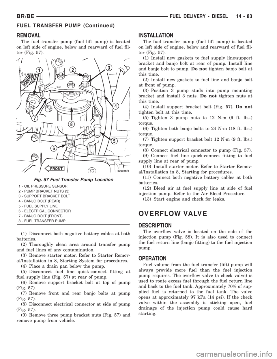
The fuel transfer pump (fuel lift pump) is located
on left side of engine, below and rearward of fuel fil-
ter (Fig. 57).
(1) Disconnect both negative battery cables at both
batteries.
(2) Thoroughly clean area around transfer pump
and fuel lines of any contamination.
(3) Remove starter motor. Refer to Starter Remov-
al/Installation in 8, Starting System for procedures.
(4) Place a drain pan below the pump.
(5) Disconnect fuel line quick-connect fitting at
fuel supply line (Fig. 57) at rear of pump.
(6) Remove support bracket bolt at top of pump
(Fig. 57).
(7) Remove front and rear banjo bolts at pump
(Fig. 57).
(8) Disconnect electrical connector at side of pump
(Fig. 57).
(9) Remove three pump bracket nuts (Fig. 57) and
remove pump from vehicle.
INSTALLATION
The fuel transfer pump (fuel lift pump) is located
on left side of engine, below and rearward of fuel fil-
ter (Fig. 57).
(1) Install new gaskets to fuel supply line/support
bracket and banjo bolt at rear of pump. Install line
and banjo bolt to pump.Do nottighten banjo bolt at
this time.
(2) Install new gaskets to fuel line and banjo bolt
at front of pump.
(3) Position 3 pump studs into pump mounting
bracket and install 3 nuts.Do nottighten nuts at
this time.
(4) Install support bracket bolt (Fig. 57).Do not
tighten bolt at this time.
(5) Tighten 3 pump nuts to 12 N´m (9 ft. lbs.)
torque.
(6) Tighten both banjo bolts to 24 N´m (18 ft. lbs.)
torque.
(7) Tighten support bracket bolt 12 N´m (9 ft. lbs.)
torque.
(8) Connect electrical connector to pump (Fig. 57).
(9) Connect fuel line quick-connect fitting to fuel
supply line at rear of pump.
(10) Install starter motor. Refer to Starter Remov-
al/Installation in 8, Starting for procedures.
(11) Connect both negative battery cables at both
batteries.
(12) Bleed air at fuel supply line at side of fuel
injection pump. Refer to the Air Bleed Procedure.
(13) Start engine and check for leaks.
OVERFLOW VALVE
DESCRIPTION
The overflow valve is located on the side of the
injection pump (Fig. 58). It is also used to connect
the fuel return line (banjo fitting) to the fuel injection
pump.
OPERATION
Fuel volume from the fuel transfer (lift) pump will
always provide more fuel than the fuel injection
pump requires. The overflow valve (a check valve) is
used to route excess fuel through the fuel return line
and back to the fuel tank. Approximately 70% of sup-
plied fuel is returned to the fuel tank. The valve
opens at approximately 97 kPa (14 psi). If the check
valve within the assembly is sticking open, fuel
drainage of the injection pump could cause hard
starting.
Fig. 57 Fuel Transfer Pump Location
1 - OIL PRESSURE SENSOR
2 - PUMP BRACKET NUTS (3)
3 - SUPPORT BRACKET BOLT
4 - BANJO BOLT (REAR)
5 - FUEL SUPPLY LINE
6 - ELECTRICAL CONNECTOR
7 - BANJO BOLT (FRONT)
8 - FUEL TRANSFER PUMP
BR/BEFUEL DELIVERY - DIESEL 14 - 83
FUEL TRANSFER PUMP (Continued)
Page 1576 of 2889
DIAGNOSIS AND TESTING - BOOST PRESSURE
Two pressure gauges attached at two different
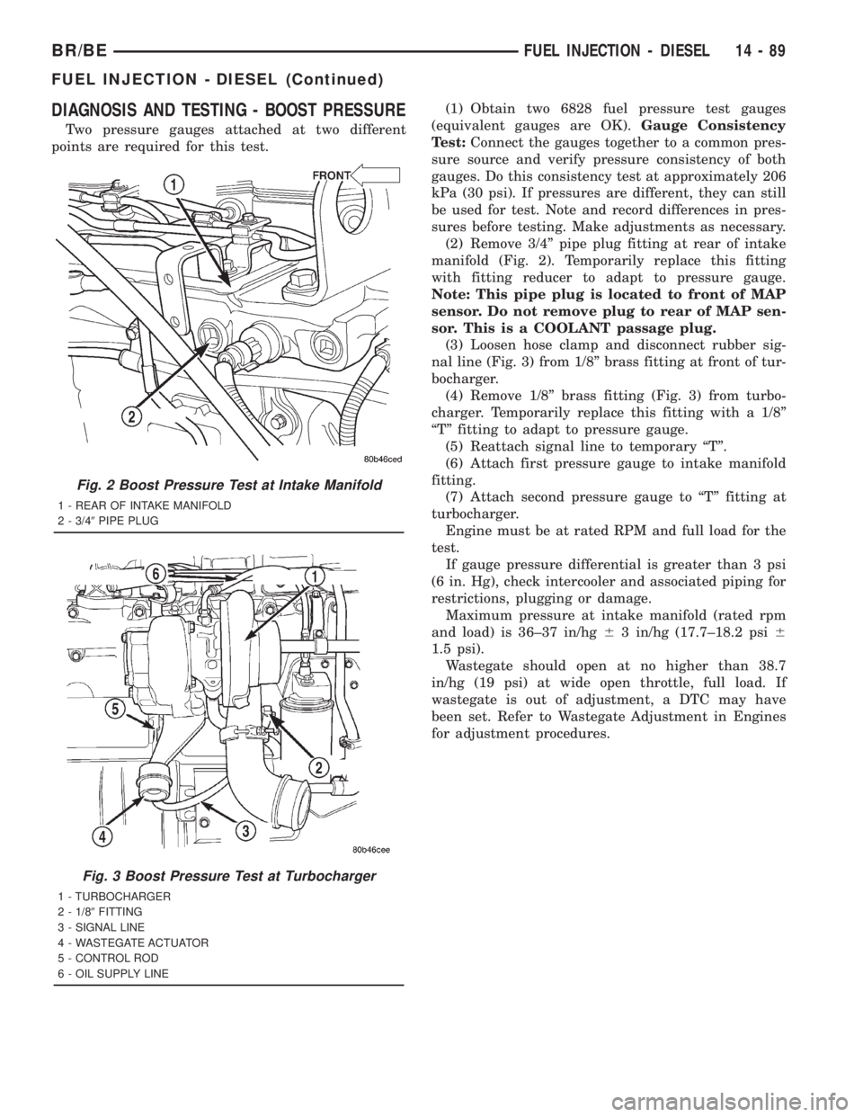
points are required for this test.(1) Obtain two 6828 fuel pressure test gauges
(equivalent gauges are OK).Gauge Consistency
Test:Connect the gauges together to a common pres-
sure source and verify pressure consistency of both
gauges. Do this consistency test at approximately 206
kPa (30 psi). If pressures are different, they can still
be used for test. Note and record differences in pres-
sures before testing. Make adjustments as necessary.
(2) Remove 3/4º pipe plug fitting at rear of intake
manifold (Fig. 2). Temporarily replace this fitting
with fitting reducer to adapt to pressure gauge.
Note: This pipe plug is located to front of MAP
sensor. Do not remove plug to rear of MAP sen-
sor. This is a COOLANT passage plug.
(3) Loosen hose clamp and disconnect rubber sig-
nal line (Fig. 3) from 1/8º brass fitting at front of tur-
bocharger.
(4) Remove 1/8º brass fitting (Fig. 3) from turbo-
charger. Temporarily replace this fitting with a 1/8º
ªTº fitting to adapt to pressure gauge.
(5) Reattach signal line to temporary ªTº.
(6) Attach first pressure gauge to intake manifold
fitting.
(7) Attach second pressure gauge to ªTº fitting at
turbocharger.
Engine must be at rated RPM and full load for the
test.
If gauge pressure differential is greater than 3 psi
(6 in. Hg), check intercooler and associated piping for
restrictions, plugging or damage.
Maximum pressure at intake manifold (rated rpm
and load) is 36±37 in/hg63 in/hg (17.7±18.2 psi6
1.5 psi).
Wastegate should open at no higher than 38.7
in/hg (19 psi) at wide open throttle, full load. If
wastegate is out of adjustment, a DTC may have
been set. Refer to Wastegate Adjustment in Engines
for adjustment procedures.
Fig. 2 Boost Pressure Test at Intake Manifold
1 - REAR OF INTAKE MANIFOLD
2 - 3/49PIPE PLUG
Fig. 3 Boost Pressure Test at Turbocharger
1 - TURBOCHARGER
2 - 1/89FITTING
3 - SIGNAL LINE
4 - WASTEGATE ACTUATOR
5 - CONTROL ROD
6 - OIL SUPPLY LINE
BR/BEFUEL INJECTION - DIESEL 14 - 89
FUEL INJECTION - DIESEL (Continued)
Page 1587 of 2889
OPERATION
The sensor located in the Bosch VP44 fuel injection
pump is used to check fuel temperature within the
injection pump and to set a Diagnostic Trouble Code
(DTC) if a specific high fuel temperature has been
reached. If high temperature has been reached,
engine power will be de-rated by the Engine Control
Module (ECM).
The sensor located in the top of the fuel filter hous-
ing is used to control the fuel heater element. Refer
to Fuel Heater Description and Operation for addi-
tional information.
INTAKE AIR HEATER
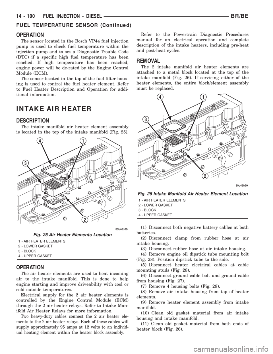
DESCRIPTION
The intake manifold air heater element assembly
is located in the top of the intake manifold (Fig. 25).
OPERATION
The air heater elements are used to heat incoming
air to the intake manifold. This is done to help
engine starting and improve driveability with cool or
cold outside temperatures.
Electrical supply for the 2 air heater elements is
controlled by the Engine Control Module (ECM)
through the 2 air heater relays. Refer to Intake Man-
ifold Air Heater Relays for more information.
Two heavy-duty cables connect the 2 air heater ele-
ments to the 2 air heater relays. Each of these cables will
supply approximately 95 amps at 12 volts to an individ-
ual heating element within the heater block assembly.
Refer to the Powertrain Diagnostic Procedures
manual for an electrical operation and complete
description of the intake heaters, including pre-heat
and post-heat cycles.
REMOVAL
The 2 intake manifold air heater elements are
attached to a metal block located at the top of the
intake manifold (Fig. 26). If servicing either of the
heater elements, the entire block/element assembly
must be replaced.
(1) Disconnect both negative battery cables at both
batteries.
(2) Disconnect clamp from rubber hose at air
intake housing.
(3) Disconnect rubber hose at air intake housing.
(4) Remove engine oil dipstick tube mounting bolt
(Fig. 28). Position dipstick tube to the side.
(5) Disconnect heater electrical cables at cable
mounting studs (Fig. 28).
(6) Disconnect ground cable bolt and ground cable
from housing (Fig. 27).
(7) Remove 4 housing bolts (Fig. 28).
(8) Remove air intake housing from top of heater
elements.
(9) Remove heater element assembly from intake
manifold.
(10) Clean old gasket material from air intake
housing and intake manifold.
(11) Clean old gasket material from both ends of
heater block (Fig. 26).
Fig. 25 Air Heater Elements Location
1 - AIR HEATER ELEMENTS
2 - LOWER GASKET
3 - BLOCK
4 - UPPER GASKET
Fig. 26 Intake Manifold Air Heater Element Location
1 - AIR HEATER ELEMENTS
2 - LOWER GASKET
3 - BLOCK
4 - UPPER GASKET
14 - 100 FUEL INJECTION - DIESELBR/BE
FUEL TEMPERATURE SENSOR (Continued)
Page 1624 of 2889
PUMP
TABLE OF CONTENTS
page page
PUMP
DESCRIPTION...........................31
OPERATION.............................31
DIAGNOSIS AND TESTING.................31
PUMP LEAKAGE.......................31
STANDARD PROCEDURE..................31
POWER STEERING PUMP - INITIAL
OPERATION...........................31
FLUSHING POWER STEERING SYSTEM.....32
REMOVAL..............................33
INSTALLATION...........................35SPECIAL TOOLS.........................36
PULLEY
REMOVAL..............................36
INSTALLATION...........................36
HOSES - PRESSURE
DESCRIPTION...........................37
OPERATION.............................37
HOSES - RETURN
DESCRIPTION...........................37
OPERATION.............................37
PUMP
DESCRIPTION
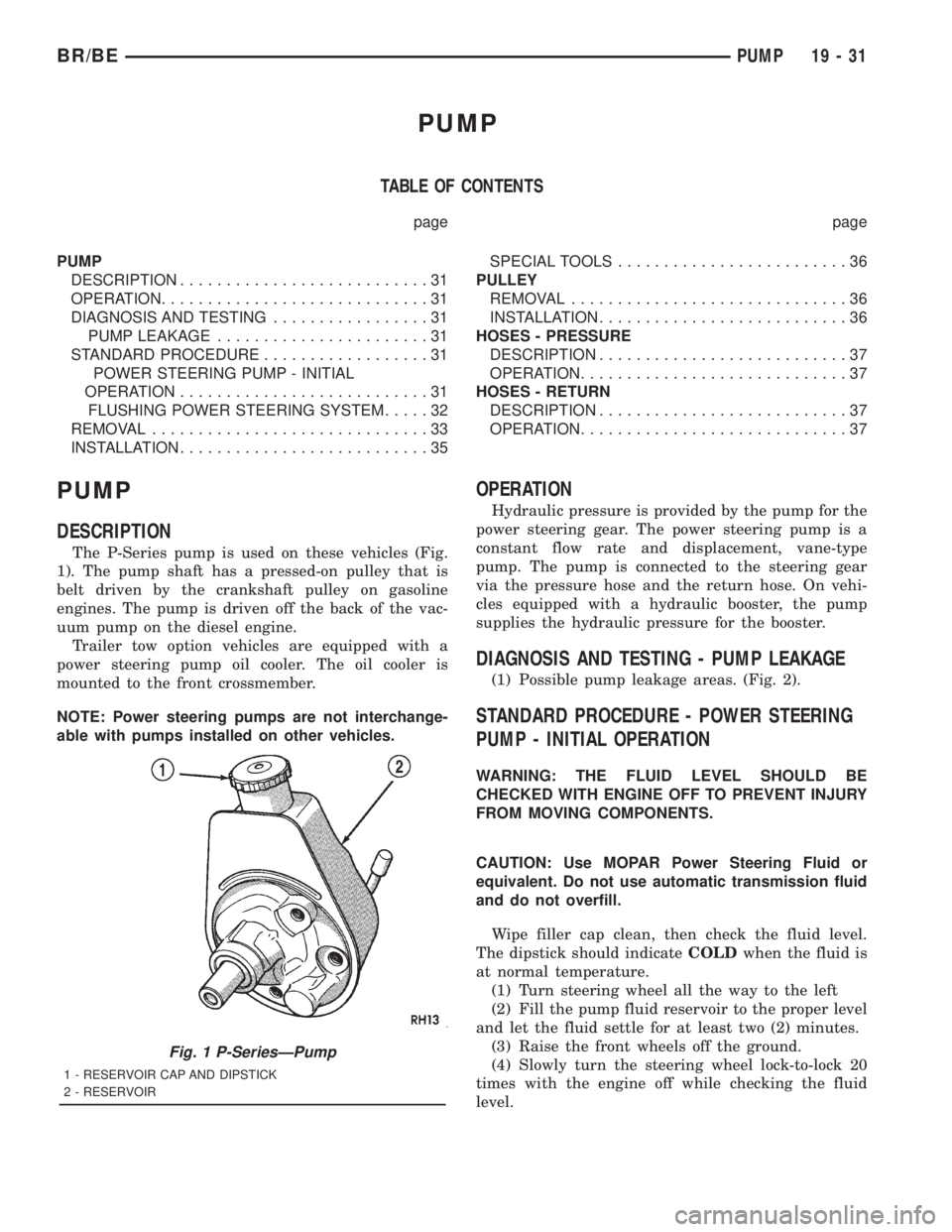
The P-Series pump is used on these vehicles (Fig.
1). The pump shaft has a pressed-on pulley that is
belt driven by the crankshaft pulley on gasoline
engines. The pump is driven off the back of the vac-
uum pump on the diesel engine.
Trailer tow option vehicles are equipped with a
power steering pump oil cooler. The oil cooler is
mounted to the front crossmember.
NOTE: Power steering pumps are not interchange-
able with pumps installed on other vehicles.
OPERATION
Hydraulic pressure is provided by the pump for the
power steering gear. The power steering pump is a
constant flow rate and displacement, vane-type
pump. The pump is connected to the steering gear
via the pressure hose and the return hose. On vehi-
cles equipped with a hydraulic booster, the pump
supplies the hydraulic pressure for the booster.
DIAGNOSIS AND TESTING - PUMP LEAKAGE
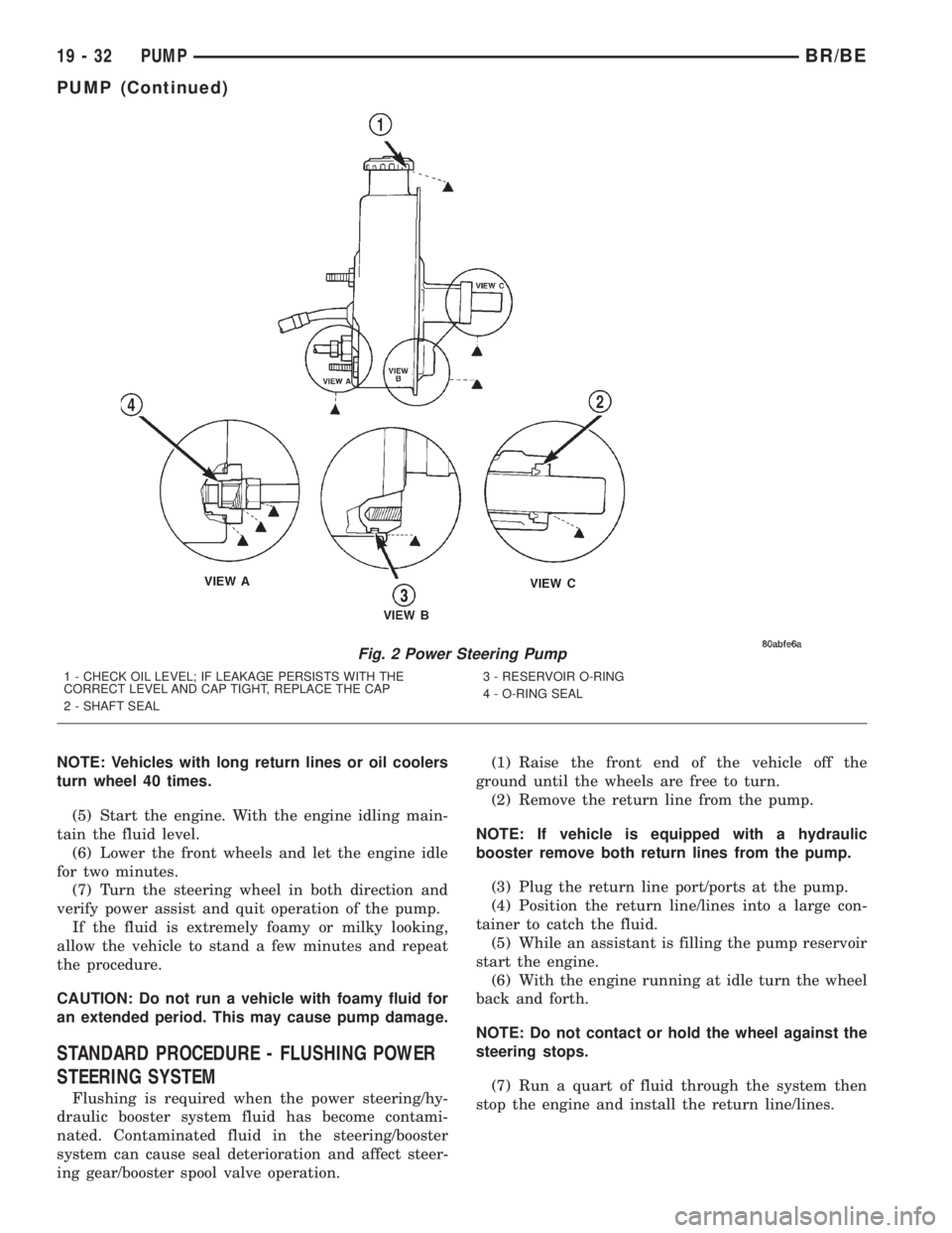
(1) Possible pump leakage areas. (Fig. 2).
STANDARD PROCEDURE - POWER STEERING
PUMP - INITIAL OPERATION
WARNING: THE FLUID LEVEL SHOULD BE
CHECKED WITH ENGINE OFF TO PREVENT INJURY
FROM MOVING COMPONENTS.
CAUTION: Use MOPAR Power Steering Fluid or
equivalent. Do not use automatic transmission fluid
and do not overfill.
Wipe filler cap clean, then check the fluid level.
The dipstick should indicateCOLDwhen the fluid is
at normal temperature.
(1) Turn steering wheel all the way to the left
(2) Fill the pump fluid reservoir to the proper level
and let the fluid settle for at least two (2) minutes.
(3) Raise the front wheels off the ground.
(4) Slowly turn the steering wheel lock-to-lock 20
times with the engine off while checking the fluid
level.
Fig. 1 P-SeriesÐPump
1 - RESERVOIR CAP AND DIPSTICK
2 - RESERVOIR
BR/BEPUMP 19 - 31
Page 1625 of 2889
NOTE: Vehicles with long return lines or oil coolers
turn wheel 40 times.
(5) Start the engine. With the engine idling main-
tain the fluid level.
(6) Lower the front wheels and let the engine idle
for two minutes.
(7) Turn the steering wheel in both direction and
verify power assist and quit operation of the pump.
If the fluid is extremely foamy or milky looking,
allow the vehicle to stand a few minutes and repeat
the procedure.
CAUTION: Do not run a vehicle with foamy fluid for
an extended period. This may cause pump damage.
STANDARD PROCEDURE - FLUSHING POWER
STEERING SYSTEM
Flushing is required when the power steering/hy-
draulic booster system fluid has become contami-
nated. Contaminated fluid in the steering/booster
system can cause seal deterioration and affect steer-
ing gear/booster spool valve operation.(1) Raise the front end of the vehicle off the
ground until the wheels are free to turn.
(2) Remove the return line from the pump.
NOTE: If vehicle is equipped with a hydraulic
booster remove both return lines from the pump.
(3) Plug the return line port/ports at the pump.
(4) Position the return line/lines into a large con-
tainer to catch the fluid.
(5) While an assistant is filling the pump reservoir
start the engine.
(6) With the engine running at idle turn the wheel
back and forth.
NOTE: Do not contact or hold the wheel against the
steering stops.
(7) Run a quart of fluid through the system then
stop the engine and install the return line/lines.
Fig. 2 Power Steering Pump
1 - CHECK OIL LEVEL; IF LEAKAGE PERSISTS WITH THE
CORRECT LEVEL AND CAP TIGHT, REPLACE THE CAP
2 - SHAFT SEAL3 - RESERVOIR O-RING
4 - O-RING SEAL
19 - 32 PUMPBR/BE
PUMP (Continued)