2001 DODGE RAM check oil
[x] Cancel search: check oilPage 1373 of 2889
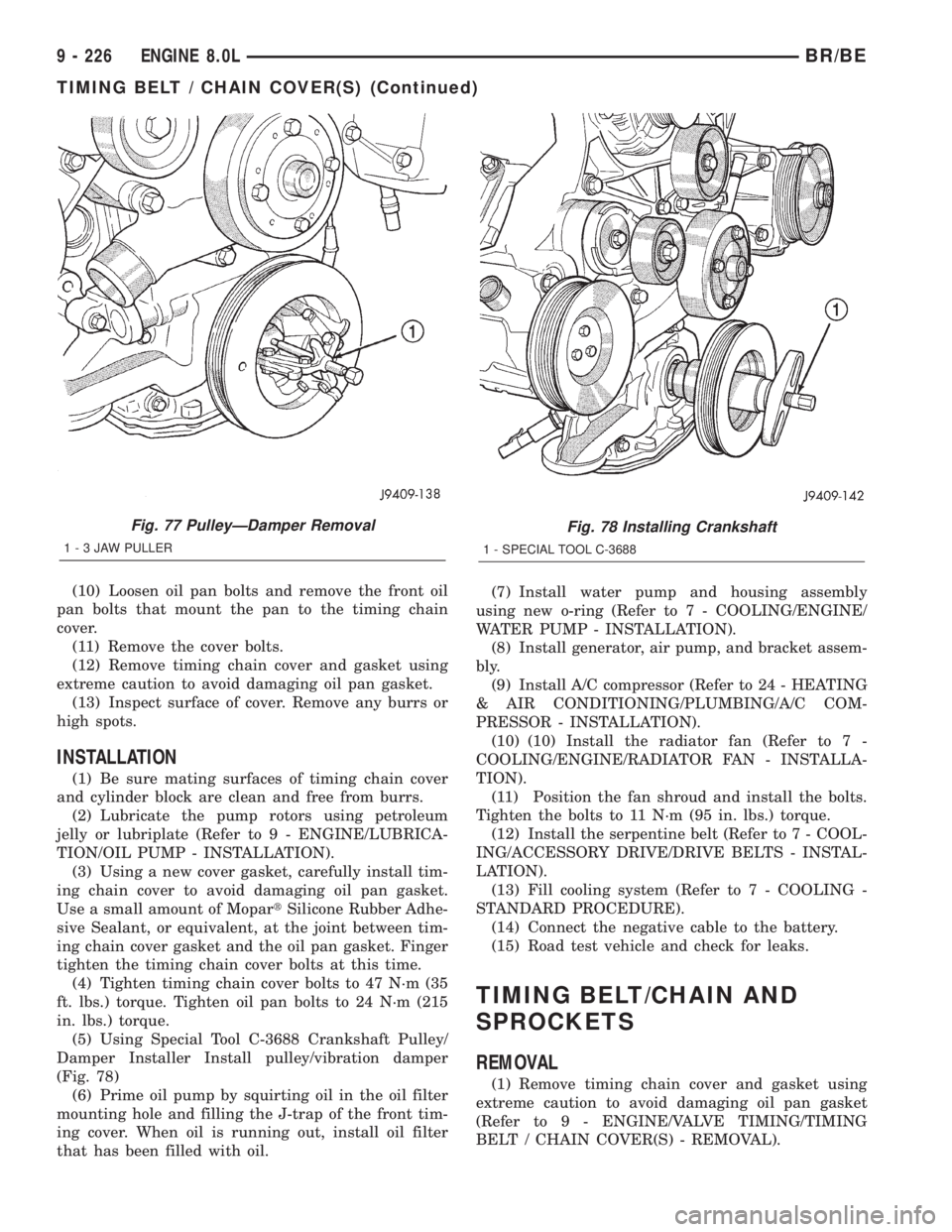
(10) Loosen oil pan bolts and remove the front oil
pan bolts that mount the pan to the timing chain
cover.
(11) Remove the cover bolts.
(12) Remove timing chain cover and gasket using
extreme caution to avoid damaging oil pan gasket.
(13) Inspect surface of cover. Remove any burrs or
high spots.
INSTALLATION
(1) Be sure mating surfaces of timing chain cover
and cylinder block are clean and free from burrs.
(2) Lubricate the pump rotors using petroleum
jelly or lubriplate (Refer to 9 - ENGINE/LUBRICA-
TION/OIL PUMP - INSTALLATION).
(3) Using a new cover gasket, carefully install tim-
ing chain cover to avoid damaging oil pan gasket.
Use a small amount of MopartSilicone Rubber Adhe-
sive Sealant, or equivalent, at the joint between tim-
ing chain cover gasket and the oil pan gasket. Finger
tighten the timing chain cover bolts at this time.
(4) Tighten timing chain cover bolts to 47 N´m (35
ft. lbs.) torque. Tighten oil pan bolts to 24 N´m (215
in. lbs.) torque.
(5) Using Special Tool C-3688 Crankshaft Pulley/
Damper Installer Install pulley/vibration damper
(Fig. 78)
(6) Prime oil pump by squirting oil in the oil filter
mounting hole and filling the J-trap of the front tim-
ing cover. When oil is running out, install oil filter
that has been filled with oil.(7) Install water pump and housing assembly
using new o-ring (Refer to 7 - COOLING/ENGINE/
WATER PUMP - INSTALLATION).
(8) Install generator, air pump, and bracket assem-
bly.
(9) Install A/C compressor (Refer to 24 - HEATING
& AIR CONDITIONING/PLUMBING/A/C COM-
PRESSOR - INSTALLATION).
(10) (10) Install the radiator fan (Refer to 7 -
COOLING/ENGINE/RADIATOR FAN - INSTALLA-
TION).
(11) Position the fan shroud and install the bolts.
Tighten the bolts to 11 N´m (95 in. lbs.) torque.
(12) Install the serpentine belt (Refer to 7 - COOL-
ING/ACCESSORY DRIVE/DRIVE BELTS - INSTAL-
LATION).
(13) Fill cooling system (Refer to 7 - COOLING -
STANDARD PROCEDURE).
(14) Connect the negative cable to the battery.
(15) Road test vehicle and check for leaks.
TIMING BELT/CHAIN AND
SPROCKETS
REMOVAL
(1) Remove timing chain cover and gasket using
extreme caution to avoid damaging oil pan gasket
(Refer to 9 - ENGINE/VALVE TIMING/TIMING
BELT / CHAIN COVER(S) - REMOVAL).
Fig. 77 PulleyÐDamper Removal
1-3JAWPULLER
Fig. 78 Installing Crankshaft
1 - SPECIAL TOOL C-3688
9 - 226 ENGINE 8.0LBR/BE
TIMING BELT / CHAIN COVER(S) (Continued)
Page 1379 of 2889
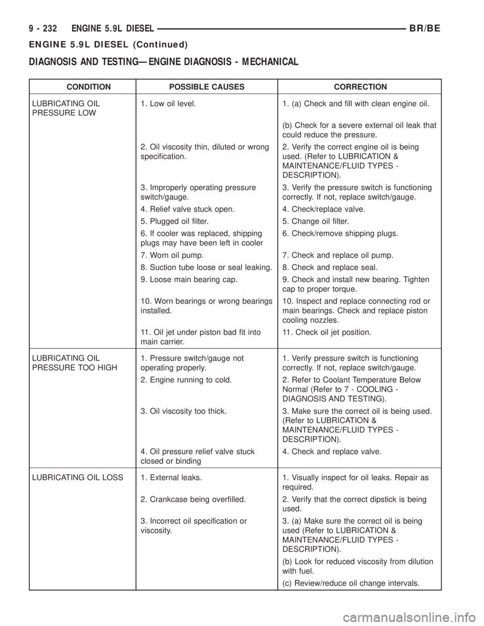
DIAGNOSIS AND TESTINGÐENGINE DIAGNOSIS - MECHANICAL
CONDITION POSSIBLE CAUSES CORRECTION
LUBRICATING OIL
PRESSURE LOW1. Low oil level. 1. (a) Check and fill with clean engine oil.
(b) Check for a severe external oil leak that
could reduce the pressure.
2. Oil viscosity thin, diluted or wrong
specification.2. Verify the correct engine oil is being
used. (Refer to LUBRICATION &
MAINTENANCE/FLUID TYPES -
DESCRIPTION).
3. Improperly operating pressure
switch/gauge.3. Verify the pressure switch is functioning
correctly. If not, replace switch/gauge.
4. Relief valve stuck open. 4. Check/replace valve.
5. Plugged oil filter. 5. Change oil filter.
6. If cooler was replaced, shipping
plugs may have been left in cooler6. Check/remove shipping plugs.
7. Worn oil pump. 7. Check and replace oil pump.
8. Suction tube loose or seal leaking. 8. Check and replace seal.
9. Loose main bearing cap. 9. Check and install new bearing. Tighten
cap to proper torque.
10. Worn bearings or wrong bearings
installed.10. Inspect and replace connecting rod or
main bearings. Check and replace piston
cooling nozzles.
11. Oil jet under piston bad fit into
main carrier.11. Check oil jet position.
LUBRICATING OIL
PRESSURE TOO HIGH1. Pressure switch/gauge not
operating properly.1. Verify pressure switch is functioning
correctly. If not, replace switch/gauge.
2. Engine running to cold. 2. Refer to Coolant Temperature Below
Normal (Refer to 7 - COOLING -
DIAGNOSIS AND TESTING).
3. Oil viscosity too thick. 3. Make sure the correct oil is being used.
(Refer to LUBRICATION &
MAINTENANCE/FLUID TYPES -
DESCRIPTION).
4. Oil pressure relief valve stuck
closed or binding4. Check and replace valve.
LUBRICATING OIL LOSS 1. External leaks. 1. Visually inspect for oil leaks. Repair as
required.
2. Crankcase being overfilled. 2. Verify that the correct dipstick is being
used.
3. Incorrect oil specification or
viscosity.3. (a) Make sure the correct oil is being
used (Refer to LUBRICATION &
MAINTENANCE/FLUID TYPES -
DESCRIPTION).
(b) Look for reduced viscosity from dilution
with fuel.
(c) Review/reduce oil change intervals.
9 - 232 ENGINE 5.9L DIESELBR/BE
ENGINE 5.9L DIESEL (Continued)
Page 1380 of 2889
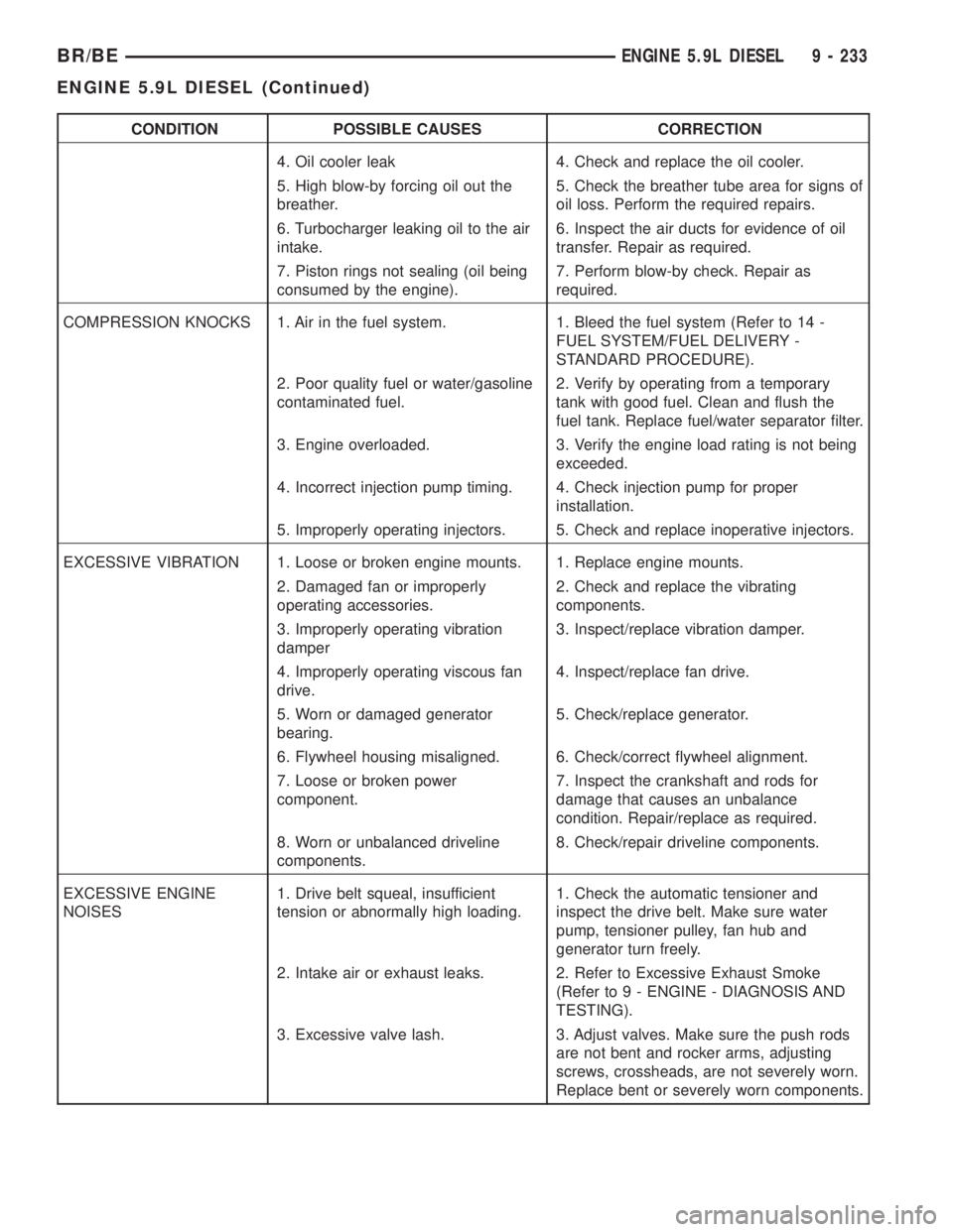
CONDITION POSSIBLE CAUSES CORRECTION
4. Oil cooler leak 4. Check and replace the oil cooler.
5. High blow-by forcing oil out the
breather.5. Check the breather tube area for signs of
oil loss. Perform the required repairs.
6. Turbocharger leaking oil to the air
intake.6. Inspect the air ducts for evidence of oil
transfer. Repair as required.
7. Piston rings not sealing (oil being
consumed by the engine).7. Perform blow-by check. Repair as
required.
COMPRESSION KNOCKS 1. Air in the fuel system. 1. Bleed the fuel system (Refer to 14 -
FUEL SYSTEM/FUEL DELIVERY -
STANDARD PROCEDURE).
2. Poor quality fuel or water/gasoline
contaminated fuel.2. Verify by operating from a temporary
tank with good fuel. Clean and flush the
fuel tank. Replace fuel/water separator filter.
3. Engine overloaded. 3. Verify the engine load rating is not being
exceeded.
4. Incorrect injection pump timing. 4. Check injection pump for proper
installation.
5. Improperly operating injectors. 5. Check and replace inoperative injectors.
EXCESSIVE VIBRATION 1. Loose or broken engine mounts. 1. Replace engine mounts.
2. Damaged fan or improperly
operating accessories.2. Check and replace the vibrating
components.
3. Improperly operating vibration
damper3. Inspect/replace vibration damper.
4. Improperly operating viscous fan
drive.4. Inspect/replace fan drive.
5. Worn or damaged generator
bearing.5. Check/replace generator.
6. Flywheel housing misaligned. 6. Check/correct flywheel alignment.
7. Loose or broken power
component.7. Inspect the crankshaft and rods for
damage that causes an unbalance
condition. Repair/replace as required.
8. Worn or unbalanced driveline
components.8. Check/repair driveline components.
EXCESSIVE ENGINE
NOISES1. Drive belt squeal, insufficient
tension or abnormally high loading.1. Check the automatic tensioner and
inspect the drive belt. Make sure water
pump, tensioner pulley, fan hub and
generator turn freely.
2. Intake air or exhaust leaks. 2. Refer to Excessive Exhaust Smoke
(Refer to 9 - ENGINE - DIAGNOSIS AND
TESTING).
3. Excessive valve lash. 3. Adjust valves. Make sure the push rods
are not bent and rocker arms, adjusting
screws, crossheads, are not severely worn.
Replace bent or severely worn components.
BR/BEENGINE 5.9L DIESEL 9 - 233
ENGINE 5.9L DIESEL (Continued)
Page 1383 of 2889
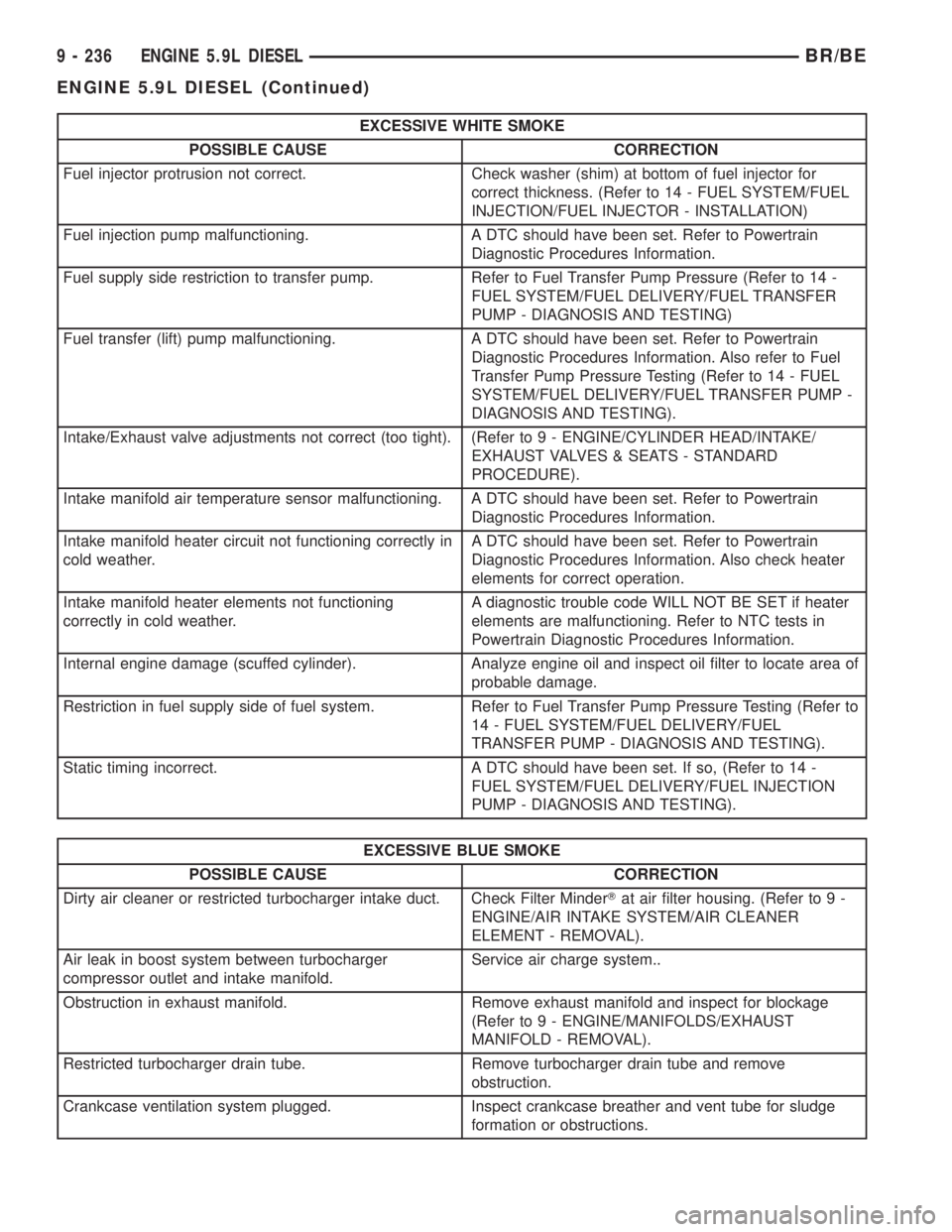
EXCESSIVE WHITE SMOKE
POSSIBLE CAUSE CORRECTION
Fuel injector protrusion not correct. Check washer (shim) at bottom of fuel injector for
correct thickness. (Refer to 14 - FUEL SYSTEM/FUEL
INJECTION/FUEL INJECTOR - INSTALLATION)
Fuel injection pump malfunctioning. A DTC should have been set. Refer to Powertrain
Diagnostic Procedures Information.
Fuel supply side restriction to transfer pump. Refer to Fuel Transfer Pump Pressure (Refer to 14 -
FUEL SYSTEM/FUEL DELIVERY/FUEL TRANSFER
PUMP - DIAGNOSIS AND TESTING)
Fuel transfer (lift) pump malfunctioning. A DTC should have been set. Refer to Powertrain
Diagnostic Procedures Information. Also refer to Fuel
Transfer Pump Pressure Testing (Refer to 14 - FUEL
SYSTEM/FUEL DELIVERY/FUEL TRANSFER PUMP -
DIAGNOSIS AND TESTING).
Intake/Exhaust valve adjustments not correct (too tight). (Refer to 9 - ENGINE/CYLINDER HEAD/INTAKE/
EXHAUST VALVES & SEATS - STANDARD
PROCEDURE).
Intake manifold air temperature sensor malfunctioning. A DTC should have been set. Refer to Powertrain
Diagnostic Procedures Information.
Intake manifold heater circuit not functioning correctly in
cold weather.A DTC should have been set. Refer to Powertrain
Diagnostic Procedures Information. Also check heater
elements for correct operation.
Intake manifold heater elements not functioning
correctly in cold weather.A diagnostic trouble code WILL NOT BE SET if heater
elements are malfunctioning. Refer to NTC tests in
Powertrain Diagnostic Procedures Information.
Internal engine damage (scuffed cylinder). Analyze engine oil and inspect oil filter to locate area of
probable damage.
Restriction in fuel supply side of fuel system. Refer to Fuel Transfer Pump Pressure Testing (Refer to
14 - FUEL SYSTEM/FUEL DELIVERY/FUEL
TRANSFER PUMP - DIAGNOSIS AND TESTING).
Static timing incorrect. A DTC should have been set. If so, (Refer to 14 -
FUEL SYSTEM/FUEL DELIVERY/FUEL INJECTION
PUMP - DIAGNOSIS AND TESTING).
EXCESSIVE BLUE SMOKE
POSSIBLE CAUSE CORRECTION
Dirty air cleaner or restricted turbocharger intake duct. Check Filter MinderTat air filter housing. (Refer to 9 -
ENGINE/AIR INTAKE SYSTEM/AIR CLEANER
ELEMENT - REMOVAL).
Air leak in boost system between turbocharger
compressor outlet and intake manifold.Service air charge system..
Obstruction in exhaust manifold. Remove exhaust manifold and inspect for blockage
(Refer to 9 - ENGINE/MANIFOLDS/EXHAUST
MANIFOLD - REMOVAL).
Restricted turbocharger drain tube. Remove turbocharger drain tube and remove
obstruction.
Crankcase ventilation system plugged. Inspect crankcase breather and vent tube for sludge
formation or obstructions.
9 - 236 ENGINE 5.9L DIESELBR/BE
ENGINE 5.9L DIESEL (Continued)
Page 1385 of 2889
vent corrosion. MopartGasket Sealant is available in
a 13 oz. aerosol can or 4oz./16 oz. can w/applicator.
FORM-IN-PLACE GASKET AND SEALER
APPLICATION
Assembling parts using a form-in-place gasket
requires care but it's easier then using precut gas-
kets.
MopartGasket Maker material should be applied
sparingly 1 mm (0.040 in.) diameter or less of sealant
to one gasket surface. Be certain the material sur-
rounds each mounting hole. Excess material can eas-
ily be wiped off. Components should be torqued in
place within 15 minutes. The use of a locating dowel
is recommended during assembly to prevent smear-
ing material off the location.
MopartEngine RTV GEN II or ATF RTV gasket
material should be applied in a continuous bead
approximately 3 mm (0.120 in.) in diameter. All
mounting holes must be circled. For corner sealing, a
3.17 or 6.35 mm (1/8 or 1/4 in.) drop is placed in the
center of the gasket contact area. Uncured sealant
may be removed with a shop towel. Components
should be torqued in place while the sealant is still
wet to the touch (within 10 minutes). The usage of a
locating dowel is recommended during assembly to
prevent smearing material off the location.
MopartGasket Sealant in an aerosol can should be
applied using a thin, even coat sprayed completely
over both surfaces to be joined, and both sides of a
gasket. Then proceed with assembly. Material in a
can w/applicator can be brushed on evenly over the
sealing surfaces. Material in an aerosol can should be
used on engines with multi-layer steel gaskets.
STANDARD PROCEDUREÐREPAIR DAMAGED
OR WORN THREADS
CAUTION: Be sure that the tapped holes maintain
the original center line.
Damaged or worn threads can be repaired. Essen-
tially, this repair consists of:
²Drilling out worn or damaged threads.
²Tapping the hole with a special Heli-Coil Tap, or
equivalent.
²Installing an insert into the tapped hole to bring
the hole back to its original thread size.
STANDARD PROCEDUREÐHYDROSTATIC
LOCK
CAUTION: DO NOT use the starter motor to rotate
the crankshaft. Severe damage could occur.When an engine is suspected of hydrostatic lock
(regardless of what caused the problem), follow the
steps below.
(1) Disconnect the negative cable(s) from the bat-
tery.
(2) Inspect air cleaner, induction system, and
intake manifold to ensure system is dry and clear of
foreign material.
(3) Place a shop towel around the fuel injectors to
catch any fluid that may possibly be under pressure
in the cylinder head. Remove the fuel injectors (Refer
to 14 - FUEL SYSTEM/FUEL INJECTION/FUEL
INJECTOR - REMOVAL).
(4) With all injectors removed, rotate the crank-
shaft using a breaker bar and socket.
(5) Identify the fluid in the cylinders (coolant, fuel,
oil, etc.).
(6) Be sure all fluid has been removed from the
cylinders.
(7) Repair engine or components as necessary to
prevent this problem from occurring again.
(8) Squirt a small amount of engine oil into the
cylinders to lubricate the walls. This will prevent
damage on restart.
(9) Install new fuel injectors (Refer to 14 - FUEL
SYSTEM/FUEL INJECTION/FUEL INJECTOR -
INSTALLATION).
(10) Drain engine oil. Remove and discard the oil
filter (Refer to 9 - ENGINE/LUBRICATION/OIL FIL-
TER - REMOVAL).
(11) Install the drain plug. Tighten the plug to 34
N´m (25 ft. lbs.) torque.
(12) Install a new oil filter (Refer to 9 - ENGINE/
LUBRICATION/OIL FILTER - INSTALLATION).
(13) Fill engine crankcase with the specified
amount and grade of oil (Refer to LUBRICATION &
MAINTENANCE/FLUID TYPES - SPECIFICA-
TIONS).
(14) Connect the negative cable(s) to the battery.
(15) Start the engine and check for any leaks.
REMOVALÐENGINE
(1) Disconnect both battery negative cables.
(2) Recover A/C refrigerant (if A/C equipped) (Refer
to 24 - HEATING & AIR CONDITIONING/PLUMB-
ING - STANDARD PROCEDURE).
(3) Raise vehicle on hoist.
(4) Drain engine coolant (Refer to 7 - COOLING -
STANDARD PROCEDURE).
(5) Remove engine oil drain plug and drain engine
oil.
(6) Lower vehicle.
(7) Remove radiator upper hose.
(8) Remove the cooling fan shroud-to-radiator
mounting bolts.
9 - 238 ENGINE 5.9L DIESELBR/BE
ENGINE 5.9L DIESEL (Continued)
Page 1398 of 2889
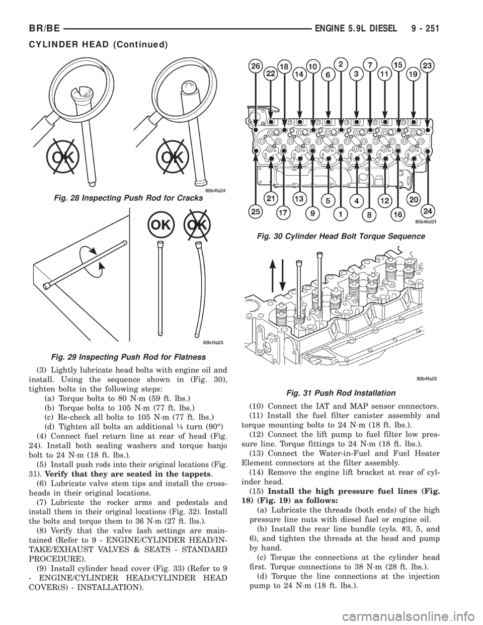
(3) Lightly lubricate head bolts with engine oil and
install. Using the sequence shown in (Fig. 30),
tighten bolts in the following steps:
(a) Torque bolts to 80 N´m (59 ft. lbs.)
(b) Torque bolts to 105 N´m (77 ft. lbs.)
(c) Re-check all bolts to 105 N´m (77 ft. lbs.)
(d) Tighten all bolts an additional ò turn (90É)
(4) Connect fuel return line at rear of head (Fig.
24). Install both sealing washers and torque banjo
bolt to 24 N´m (18 ft. lbs.).
(5)
Install push rods into their original locations (Fig.
31).Verify that they are seated in the tappets
.
(6) Lubricate valve stem tips and install the cross-
heads in their original locations.
(7)
Lubricate the rocker arms and pedestals and
install them in their original locations (Fig. 32). Install
the bolts and torque them to 36 N´m (27 ft. lbs.).
(8) Verify that the valve lash settings are main-
tained (Refer to 9 - ENGINE/CYLINDER HEAD/IN-
TAKE/EXHAUST VALVES & SEATS - STANDARD
PROCEDURE).
(9) Install cylinder head cover (Fig. 33) (Refer to 9
- ENGINE/CYLINDER HEAD/CYLINDER HEAD
COVER(S) - INSTALLATION).(10) Connect the IAT and MAP sensor connectors.
(11) Install the fuel filter canister assembly and
torque mounting bolts to 24 N´m (18 ft. lbs.).
(12) Connect the lift pump to fuel filter low pres-
sure line. Torque fittings to 24 N´m (18 ft. lbs.).
(13) Connect the Water-in-Fuel and Fuel Heater
Element connectors at the filter assembly.
(14) Remove the engine lift bracket at rear of cyl-
inder head.
(15)Install the high pressure fuel lines (Fig.
18) (Fig. 19) as follows:
(a) Lubricate the threads (both ends) of the high
pressure line nuts with diesel fuel or engine oil.
(b) Install the rear line bundle (cyls. #3, 5, and
6), and tighten the threads at the head and pump
by hand.
(c) Torque the connections at the cylinder head
first. Torque connections to 38 N´m (28 ft. lbs.).
(d) Torque the line connections at the injection
pump to 24 N´m (18 ft. lbs.).
Fig. 28 Inspecting Push Rod for Cracks
Fig. 29 Inspecting Push Rod for Flatness
Fig. 30 Cylinder Head Bolt Torque Sequence
Fig. 31 Push Rod Installation
BR/BEENGINE 5.9L DIESEL 9 - 251
CYLINDER HEAD (Continued)
Page 1399 of 2889
(e) Install the front line bundle (cyls. #1, 2, and
4) following the same procedure used for the rear
line bundle.
(f) Torque the connections at the cylinder head
first. Torque connections to 38 N´m (28 ft. lbs.).
(g) Torque the line connections at the injection
pump to 24 N´m (18 ft. lbs.).
(h) Install the injection line support bracket to
intake cover/cylinder head bolts and torque to 24
N´m (18 ft. lbs.).
(16) Install the engine lift bracket at the rear of
cylinder head. Torque to 77 N´m (57 ft. lbs.).
(17) Install the fuel filter to injection pump low
pressure line. Inspect and replace sealing washers if
necessary. Torque banjo bolts to 24 N´m (18 ft. lbs.).
(18) Using new gaskets, install the intake grid
heater and air inlet housing. Torque bolts to 24 N´m
(18 ft. lbs.).
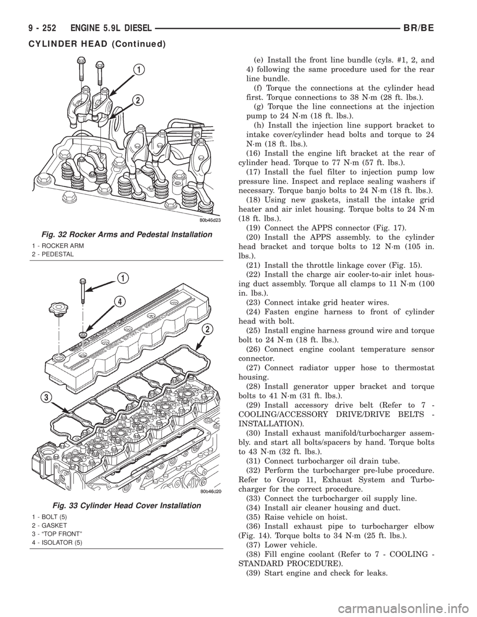
(19) Connect the APPS connector (Fig. 17).
(20) Install the APPS assembly. to the cylinder
head bracket and torque bolts to 12 N´m (105 in.
lbs.).
(21) Install the throttle linkage cover (Fig. 15).
(22) Install the charge air cooler-to-air inlet hous-
ing duct assembly. Torque all clamps to 11 N´m (100
in. lbs.).
(23) Connect intake grid heater wires.
(24) Fasten engine harness to front of cylinder
head with bolt.
(25) Install engine harness ground wire and torque
bolt to 24 N´m (18 ft. lbs.).
(26) Connect engine coolant temperature sensor
connector.
(27) Connect radiator upper hose to thermostat
housing.
(28) Install generator upper bracket and torque
bolts to 41 N´m (31 ft. lbs.).
(29) Install accessory drive belt (Refer to 7 -
COOLING/ACCESSORY DRIVE/DRIVE BELTS -
INSTALLATION).
(30) Install exhaust manifold/turbocharger assem-
bly. and start all bolts/spacers by hand. Torque bolts
to 43 N´m (32 ft. lbs.).
(31) Connect turbocharger oil drain tube.
(32) Perform the turbocharger pre-lube procedure.
Refer to Group 11, Exhaust System and Turbo-
charger for the correct procedure.
(33) Connect the turbocharger oil supply line.
(34) Install air cleaner housing and duct.
(35) Raise vehicle on hoist.
(36) Install exhaust pipe to turbocharger elbow
(Fig. 14). Torque bolts to 34 N´m (25 ft. lbs.).
(37) Lower vehicle.
(38) Fill engine coolant (Refer to 7 - COOLING -
STANDARD PROCEDURE).
(39) Start engine and check for leaks.
Fig. 32 Rocker Arms and Pedestal Installation
1 - ROCKER ARM
2 - PEDESTAL
Fig. 33 Cylinder Head Cover Installation
1 - BOLT (5)
2 - GASKET
3 - ªTOP FRONTº
4 - ISOLATOR (5)
9 - 252 ENGINE 5.9L DIESELBR/BE
CYLINDER HEAD (Continued)
Page 1412 of 2889
(11) Check the bore cleanliness by wiping with a
white, lint free, lightly oiled cloth. If grit residue is
still present, repeat the cleaning process until all res-
idue is removed. Wash the bores and the complete
block assembly with solvent and dry with compressed
air.
(12) Be sure to remove the tape covering the lube
holes after the cleaning process is complete.
STANDARD PROCEDUREÐCYLINDER BORE
REPAIR
Cylinder bore(s) can be repaired by one of two
methods:
²Method 1:ÐOver boring and using oversize pis-
tons and rings.
²Method 2:ÐBoring and installing a repair sleeve
to return the bore to standard dimensions.
METHOD 1ÐOVERSIZE BORE
Cylinder bore(s) can be repaired by one of two
methods:
Oversize pistons and rings are available in two
sizes - 0.50 mm (0.0197 inch) and 1.00 mm (0.0393
inch).
Any combination of standard, 0.50 mm (0.0197
inch) or 1.00 mm (0.0393 inch) overbore may be used
in the same engine.
If more than 1.00 mm (0.0393 inch) overbore is
needed, a repair sleeve can be installed (refer to
Method 2ÐRepair Sleeve).
Cylinder block bores may be bored twice before use
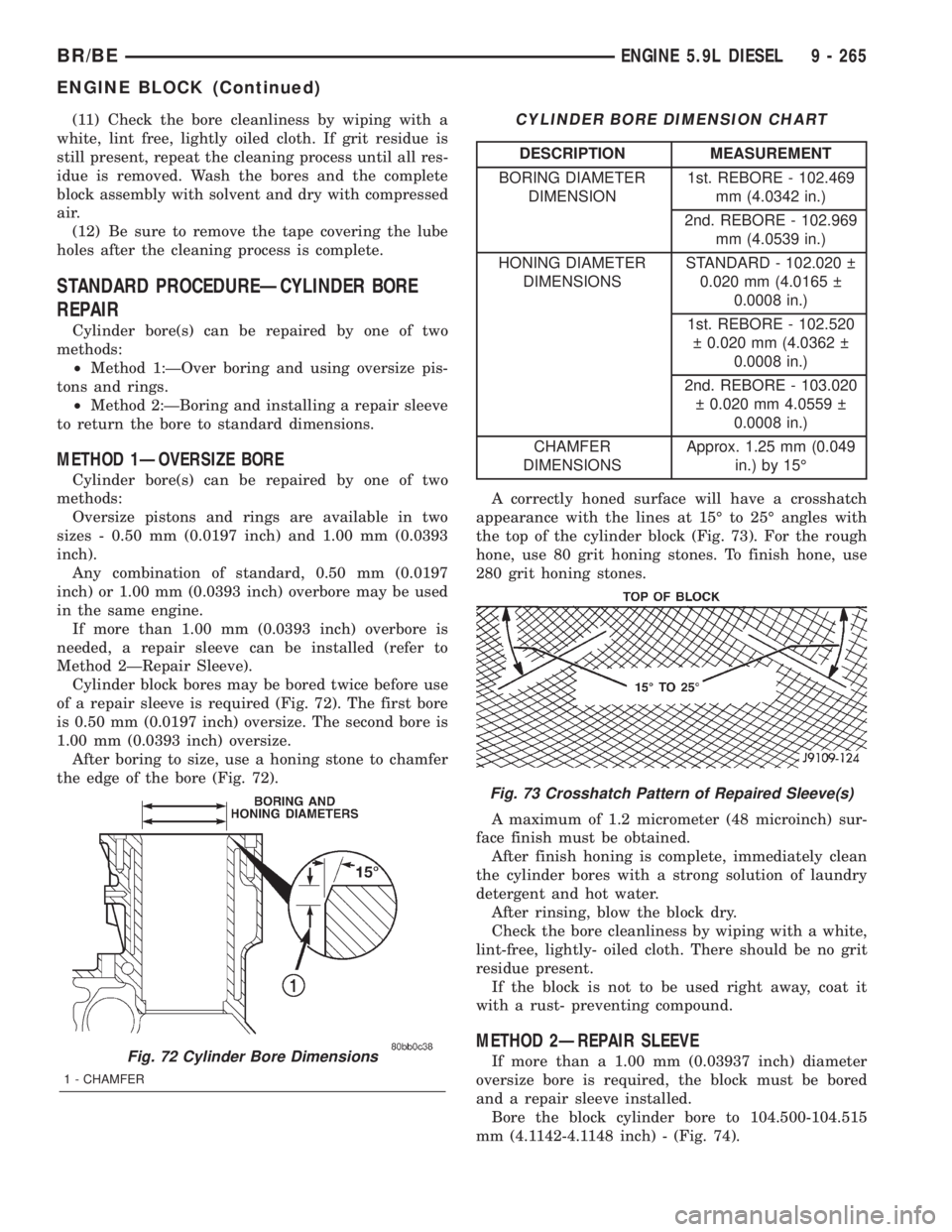
of a repair sleeve is required (Fig. 72). The first bore
is 0.50 mm (0.0197 inch) oversize. The second bore is
1.00 mm (0.0393 inch) oversize.
After boring to size, use a honing stone to chamfer
the edge of the bore (Fig. 72).
CYLINDER BORE DIMENSION CHART
DESCRIPTION MEASUREMENT
BORING DIAMETER
DIMENSION1st. REBORE - 102.469
mm (4.0342 in.)
2nd. REBORE - 102.969
mm (4.0539 in.)
HONING DIAMETER
DIMENSIONSSTANDARD - 102.020
0.020 mm (4.0165
0.0008 in.)
1st. REBORE - 102.520
0.020 mm (4.0362
0.0008 in.)
2nd. REBORE - 103.020
0.020 mm 4.0559
0.0008 in.)
CHAMFER
DIMENSIONSApprox. 1.25 mm (0.049
in.) by 15É
A correctly honed surface will have a crosshatch
appearance with the lines at 15É to 25É angles with
the top of the cylinder block (Fig. 73). For the rough
hone, use 80 grit honing stones. To finish hone, use
280 grit honing stones.
A maximum of 1.2 micrometer (48 microinch) sur-
face finish must be obtained.
After finish honing is complete, immediately clean
the cylinder bores with a strong solution of laundry
detergent and hot water.
After rinsing, blow the block dry.
Check the bore cleanliness by wiping with a white,
lint-free, lightly- oiled cloth. There should be no grit
residue present.
If the block is not to be used right away, coat it
with a rust- preventing compound.
METHOD 2ÐREPAIR SLEEVE
If more than a 1.00 mm (0.03937 inch) diameter
oversize bore is required, the block must be bored
and a repair sleeve installed.
Bore the block cylinder bore to 104.500-104.515
mm (4.1142-4.1148 inch) - (Fig. 74).Fig. 72 Cylinder Bore Dimensions
1 - CHAMFER
Fig. 73 Crosshatch Pattern of Repaired Sleeve(s)
BR/BEENGINE 5.9L DIESEL 9 - 265
ENGINE BLOCK (Continued)