2001 DODGE RAM check oil
[x] Cancel search: check oilPage 1354 of 2889
NOTE: Worn valve guides or cocked springs are
sometimes mistaken for noisy tappets. If such is
the case, noise may be dampened by applying side
thrust on the valve spring. If noise is not apprecia-
bly reduced, it can be assumed the noise is in the
tappet. Inspect the rocker arm push rod sockets
and push rod ends for wear.
(3) Valve tappet noise ranges from light noise to a
heavy click. A light noise is usually caused by exces-
sive leak-down around the unit plunger, or by the
plunger partially sticking in the tappet body cylinder.
The tappet should be replaced. A heavy click is
caused by a tappet check valve not seating, or by for-
eign particles wedged between the plunger and the
tappet body. This will cause the plunger to stick in
the down position. This heavy click will be accompa-
nied by excessive clearance between the valve stem
and rocker arm as valve closes. In either case, tappet
assembly should be removed for inspection and clean-
ing.
(4) The valve train generates a noise very much
like a light tappet noise during normal operation.
Care must be taken to ensure that tappets are mak-
ing the noise. If more than one tappet seems to be
noisy, it's probably not the tappets.
LEAK-DOWN TEST
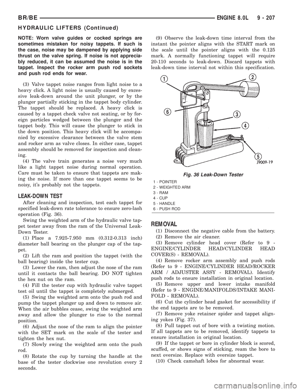
After cleaning and inspection, test each tappet for
specified leak-down rate tolerance to ensure zero-lash
operation (Fig. 36).
Swing the weighted arm of the hydraulic valve tap-
pet tester away from the ram of the Universal Leak-
Down Tester.
(1) Place a 7.925-7.950 mm (0.312-0.313 inch)
diameter ball bearing on the plunger cap of the tap-
pet.
(2) Lift the ram and position the tappet (with the
ball bearing) inside the tester cup.
(3) Lower the ram, then adjust the nose of the ram
until it contacts the ball bearing. DO NOT tighten
the hex nut on the ram.
(4) Fill the tester cup with hydraulic valve tappet
test oil until the tappet is completely submerged.
(5) Swing the weighted arm onto the push rod and
pump the tappet plunger up and down to remove air.
When the air bubbles cease, swing the weighted arm
away and allow the plunger to rise to the normal
position.
(6) Adjust the nose of the ram to align the pointer
with the SET mark on the scale of the tester and
tighten the hex nut.
(7) Slowly swing the weighted arm onto the push
rod.
(8) Rotate the cup by turning the handle at the
base of the tester clockwise one revolution every 2
seconds.(9) Observe the leak-down time interval from the
instant the pointer aligns with the START mark on
the scale until the pointer aligns with the 0.125
mark. A normally functioning tappet will require
20-110 seconds to leak-down. Discard tappets with
leak-down time interval not within this specification.
REMOVAL
(1) Disconnect the negative cable from the battery.
(2) Remove the air cleaner.
(3) Remove cylinder head cover (Refer to 9 -
ENGINE/CYLINDER HEAD/CYLINDER HEAD
COVER(S) - REMOVAL).
(4) Remove rocker arm assembly and push rods
(Refer to 9 - ENGINE/CYLINDER HEAD/ROCKER
ARM / ADJUSTER ASSY - REMOVAL). Identify
push rods to ensure installation in original location.
(5) Remove upper and lower intake manifold
(Refer to 9 - ENGINE/MANIFOLDS/INTAKE MANI-
FOLD - REMOVAL).
(6) Cut the cylinder head gasket for accessibility if
the end tappets are to be removed.
(7) Remove yoke retainer spider and tappet align-
ing yokes (Fig. 37).
(8) Pull tappet out of bore with a twisting motion.
If all tappets are to be removed, identify tappets to
ensure installation in original location.
(9) If the tappet or bore in cylinder block is scored,
scuffed, or shows signs of sticking, ream the bore to
next oversize. Replace with oversize tappet.
(10) Check camshaft lobes for abnormal wear.
Fig. 36 Leak-Down Tester
1 - POINTER
2 - WEIGHTED ARM
3 - RAM
4 - CUP
5 - HANDLE
6 - PUSH ROD
BR/BEENGINE 8.0L 9 - 207
HYDRAULIC LIFTERS (Continued)
Page 1355 of 2889
CLEANING
Clean tappet with a suitable solvent. Rinse in hot
water and blow dry with a clean shop rag or com-
pressed air.
INSTALLATION
(1) Lubricate tappets.
(2) Install tappets in their original positions.
Ensure that the oil bleed hole (if so equipped)
faces forward.
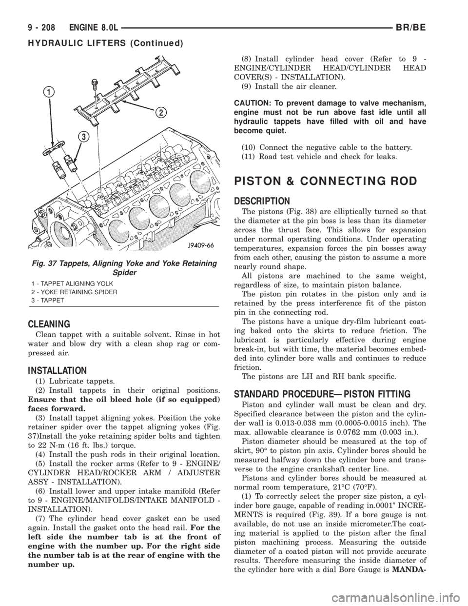
(3) Install tappet aligning yokes. Position the yoke
retainer spider over the tappet aligning yokes (Fig.
37)Install the yoke retaining spider bolts and tighten
to 22 N´m (16 ft. lbs.) torque.
(4) Install the push rods in their original location.
(5) Install the rocker arms (Refer to 9 - ENGINE/
CYLINDER HEAD/ROCKER ARM / ADJUSTER
ASSY - INSTALLATION).
(6) Install lower and upper intake manifold (Refer
to 9 - ENGINE/MANIFOLDS/INTAKE MANIFOLD -
INSTALLATION).
(7) The cylinder head cover gasket can be used
again. Install the gasket onto the head rail.For the
left side the number tab is at the front of
engine with the number up. For the right side
the number tab is at the rear of engine with the
number up.(8) Install cylinder head cover (Refer to 9 -
ENGINE/CYLINDER HEAD/CYLINDER HEAD
COVER(S) - INSTALLATION).
(9) Install the air cleaner.
CAUTION: To prevent damage to valve mechanism,
engine must not be run above fast idle until all
hydraulic tappets have filled with oil and have
become quiet.
(10) Connect the negative cable to the battery.
(11) Road test vehicle and check for leaks.
PISTON & CONNECTING ROD
DESCRIPTION
The pistons (Fig. 38) are elliptically turned so that
the diameter at the pin boss is less than its diameter
across the thrust face. This allows for expansion
under normal operating conditions. Under operating
temperatures, expansion forces the pin bosses away
from each other, causing the piston to assume a more
nearly round shape.
All pistons are machined to the same weight,
regardless of size, to maintain piston balance.
The piston pin rotates in the piston only and is
retained by the press interference fit of the piston
pin in the connecting rod.
The pistons have a unique dry-film lubricant coat-
ing baked onto the skirts to reduce friction. The
lubricant is particularly effective during engine
break-in, but with time, the material becomes embed-
ded into cylinder bore walls and continues to reduce
friction.
The pistons are LH and RH bank specific.
STANDARD PROCEDUREÐPISTON FITTING
Piston and cylinder wall must be clean and dry.
Specified clearance between the piston and the cylin-
der wall is 0.013-0.038 mm (0.0005-0.0015 inch). The
max. allowable clearance is 0.0762 mm (0.003 in.).
Piston diameter should be measured at the top of
skirt, 90É to piston pin axis. Cylinder bores should be
measured halfway down the cylinder bore and trans-
verse to the engine crankshaft center line.
Pistons and cylinder bores should be measured at
normal room temperature, 21ÉC (70ÉF).
(1) To correctly select the proper size piston, a cyl-
inder bore gauge, capable of reading in.00019INCRE-
MENTS is required (Fig. 39). If a bore gauge is not
available, do not use an inside micrometer.The coat-
ing material is applied to the piston after the final
piston machining process. Measuring the outside
diameter of a coated piston will not provide accurate
results. Therefore measuring the inside diameter of
the cylinder bore with a dial Bore Gauge isMANDA-
Fig. 37 Tappets, Aligning Yoke and Yoke Retaining
Spider
1 - TAPPET ALIGNING YOLK
2 - YOKE RETAINING SPIDER
3 - TAPPET
9 - 208 ENGINE 8.0LBR/BE
HYDRAULIC LIFTERS (Continued)
Page 1356 of 2889
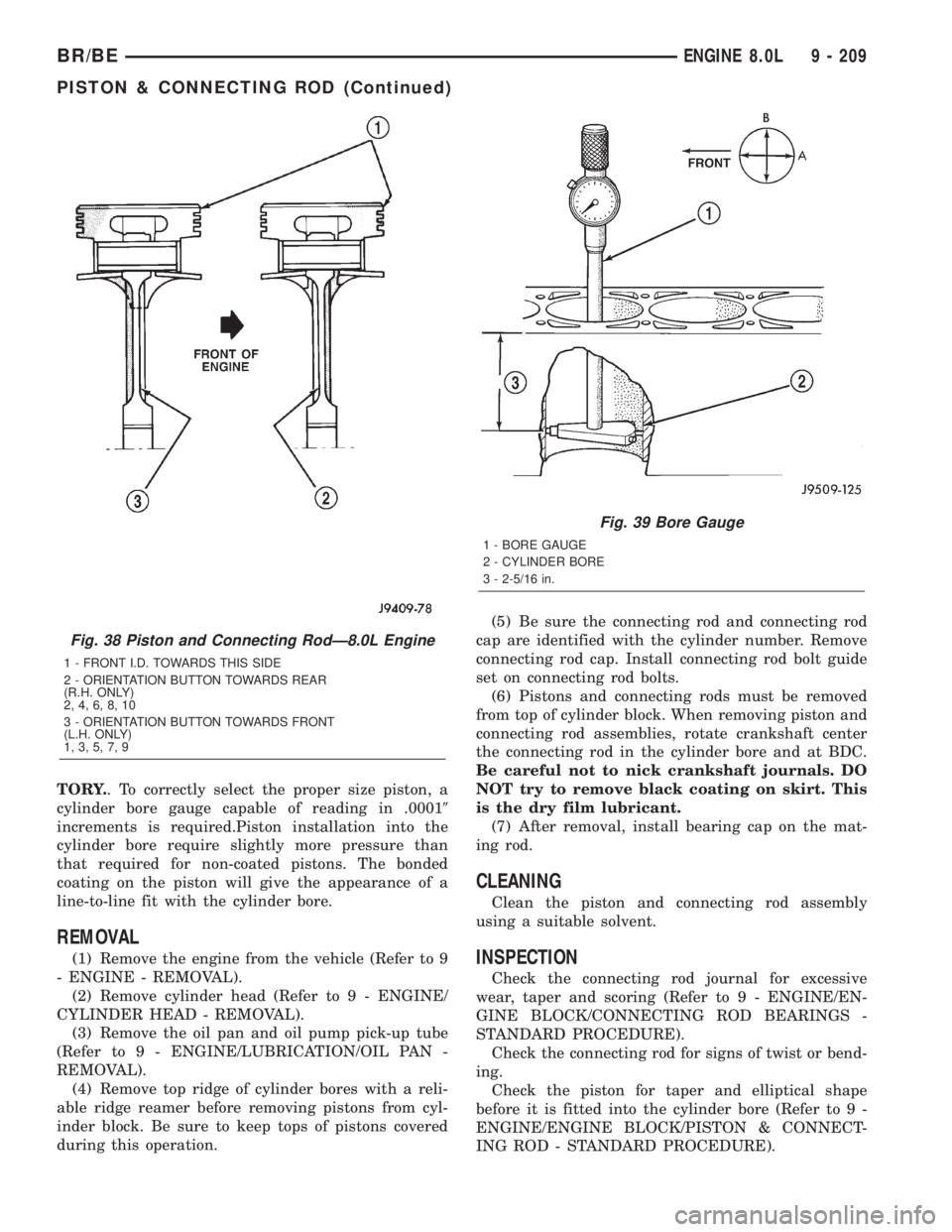
TORY.. To correctly select the proper size piston, a
cylinder bore gauge capable of reading in .00019
increments is required.Piston installation into the
cylinder bore require slightly more pressure than
that required for non-coated pistons. The bonded
coating on the piston will give the appearance of a
line-to-line fit with the cylinder bore.
REMOVAL
(1) Remove the engine from the vehicle (Refer to 9
- ENGINE - REMOVAL).
(2) Remove cylinder head (Refer to 9 - ENGINE/
CYLINDER HEAD - REMOVAL).
(3) Remove the oil pan and oil pump pick-up tube
(Refer to 9 - ENGINE/LUBRICATION/OIL PAN -
REMOVAL).
(4) Remove top ridge of cylinder bores with a reli-
able ridge reamer before removing pistons from cyl-
inder block. Be sure to keep tops of pistons covered
during this operation.(5) Be sure the connecting rod and connecting rod
cap are identified with the cylinder number. Remove
connecting rod cap. Install connecting rod bolt guide
set on connecting rod bolts.
(6) Pistons and connecting rods must be removed
from top of cylinder block. When removing piston and
connecting rod assemblies, rotate crankshaft center
the connecting rod in the cylinder bore and at BDC.
Be careful not to nick crankshaft journals. DO
NOT try to remove black coating on skirt. This
is the dry film lubricant.
(7) After removal, install bearing cap on the mat-
ing rod.
CLEANING
Clean the piston and connecting rod assembly
using a suitable solvent.
INSPECTION
Check the connecting rod journal for excessive
wear, taper and scoring (Refer to 9 - ENGINE/EN-
GINE BLOCK/CONNECTING ROD BEARINGS -
STANDARD PROCEDURE).
Check the connecting rod for signs of twist or bend-
ing.
Check the piston for taper and elliptical shape
before it is fitted into the cylinder bore (Refer to 9 -
ENGINE/ENGINE BLOCK/PISTON & CONNECT-
ING ROD - STANDARD PROCEDURE).
Fig. 38 Piston and Connecting RodÐ8.0L Engine
1 - FRONT I.D. TOWARDS THIS SIDE
2 - ORIENTATION BUTTON TOWARDS REAR
(R.H. ONLY)
2, 4, 6, 8, 10
3 - ORIENTATION BUTTON TOWARDS FRONT
(L.H. ONLY)
1, 3, 5, 7, 9
Fig. 39 Bore Gauge
1 - BORE GAUGE
2 - CYLINDER BORE
3 - 2-5/16 in.
BR/BEENGINE 8.0L 9 - 209
PISTON & CONNECTING ROD (Continued)
Page 1357 of 2889
Check the piston for scoring, or scraping marks in
the piston skirts. Check the ring lands for cracks
and/or deterioration.
INSTALLATION
(1) Check the crankshaft connecting rod journal
for excessive wear, taper and scoring.
(2) Check the cylinder block bore for out-of-round,
taper, scoring and scuffing.
(3) Be sure that compression ring gaps are stag-
gered so that neither is in line with oil ring rail gap.
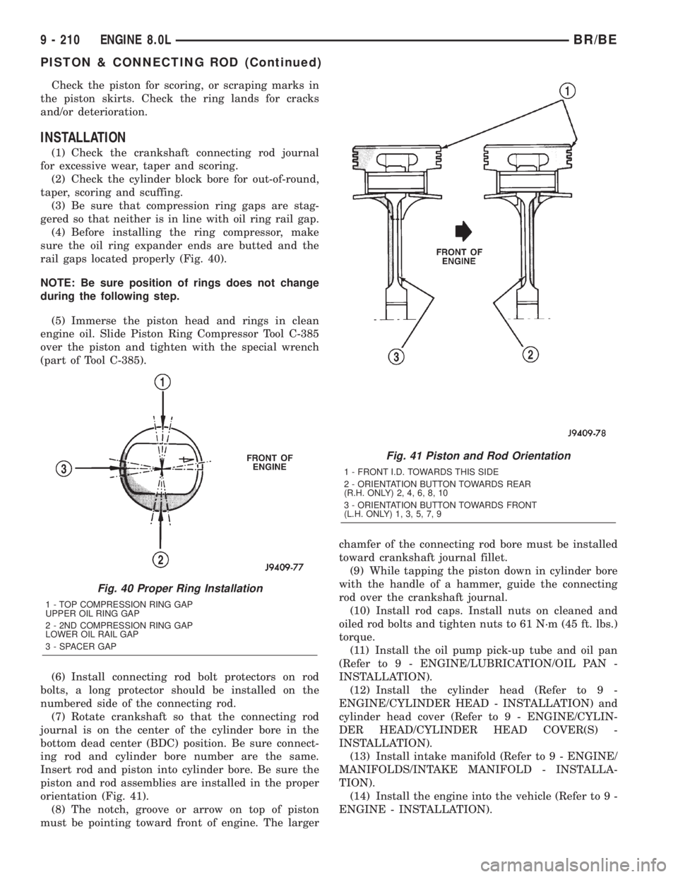
(4) Before installing the ring compressor, make
sure the oil ring expander ends are butted and the
rail gaps located properly (Fig. 40).
NOTE: Be sure position of rings does not change
during the following step.
(5) Immerse the piston head and rings in clean
engine oil. Slide Piston Ring Compressor Tool C-385
over the piston and tighten with the special wrench
(part of Tool C-385).
(6) Install connecting rod bolt protectors on rod
bolts, a long protector should be installed on the
numbered side of the connecting rod.
(7) Rotate crankshaft so that the connecting rod
journal is on the center of the cylinder bore in the
bottom dead center (BDC) position. Be sure connect-
ing rod and cylinder bore number are the same.
Insert rod and piston into cylinder bore. Be sure the
piston and rod assemblies are installed in the proper
orientation (Fig. 41).
(8) The notch, groove or arrow on top of piston
must be pointing toward front of engine. The largerchamfer of the connecting rod bore must be installed
toward crankshaft journal fillet.
(9) While tapping the piston down in cylinder bore
with the handle of a hammer, guide the connecting
rod over the crankshaft journal.
(10) Install rod caps. Install nuts on cleaned and
oiled rod bolts and tighten nuts to 61 N´m (45 ft. lbs.)
torque.
(11) Install the oil pump pick-up tube and oil pan
(Refer to 9 - ENGINE/LUBRICATION/OIL PAN -
INSTALLATION).
(12) Install the cylinder head (Refer to 9 -
ENGINE/CYLINDER HEAD - INSTALLATION) and
cylinder head cover (Refer to 9 - ENGINE/CYLIN-
DER HEAD/CYLINDER HEAD COVER(S) -
INSTALLATION).
(13) Install intake manifold (Refer to 9 - ENGINE/
MANIFOLDS/INTAKE MANIFOLD - INSTALLA-
TION).
(14) Install the engine into the vehicle (Refer to 9 -
ENGINE - INSTALLATION).
Fig. 40 Proper Ring Installation
1 - TOP COMPRESSION RING GAP
UPPER OIL RING GAP
2 - 2ND COMPRESSION RING GAP
LOWER OIL RAIL GAP
3 - SPACER GAP
Fig. 41 Piston and Rod Orientation
1 - FRONT I.D. TOWARDS THIS SIDE
2 - ORIENTATION BUTTON TOWARDS REAR
(R.H. ONLY) 2, 4, 6, 8, 10
3 - ORIENTATION BUTTON TOWARDS FRONT
(L.H. ONLY) 1, 3, 5, 7, 9
9 - 210 ENGINE 8.0LBR/BE
PISTON & CONNECTING ROD (Continued)
Page 1362 of 2889
rotates. This oil throwoff lubricates the camshaft
lobes, cylinder walls, and piston pins.
The hydraulic valve tappets receive oil directly
from the main oil gallery. The camshaft bearings
receive oil from the main bearing galleries. The front
camshaft bearing journal passes oil through the cam-
shaft sprocket to the timing chain. Oil drains back to
the oil pan under the No. 1 main bearing cap.
The oil supply for the rocker arms and bridged
pivot assemblies is provided by the hydraulic valve
tappets, which pass oil through hollow push rods to a
hole in the corresponding rocker arm. Oil from the
rocker arm lubricates the valve train components.
The oil then passes down through the push rod guide
holes and the oil drain-back passages in the cylinder
head, past the valve tappet area, and then returns to
the oil pan (Fig. 52).
DIAGNOSIS AND TESTINGÐENGINE OIL
LEAKS
Begin with a through visual inspection of the
engine, particularly at the area of the suspected leak.
If an oil leak source is not readily identifiable, the
following steps should be followed:
(1) Do not clean or degrease the engine at this
time because some solvents may cause rubber to
swell, temporarily stopping the leak.
(2) Add an oil-soluble dye (use as recommended by
manufacturer). Start the engine and let idle for
approximately 15 minutes. Check the oil dipstick to
be sure the dye is thoroughly mixed as indicated
with a bright yellow color under a black light source.
(3) Using a black light, inspect the entire engine
for fluorescent dye, particularly at the suspected area
of oil leak. If the oil leak is found and identified,
repair per service manual instructions.
(4) If dye is not observed, drive the vehicle at var-
ious speeds for approximately 24km (15 miles), and
repeat previous step.(5) If the oil leak source is not positively identified
at this time, proceed with the air leak detection test
method as follows:
(6) Disconnect the breather cap to air cleaner hose
at the breather cap end. Cap or plug breather cap
nipple.
(7) Remove the PCV valve from the cylinder head
cover. Cap or plug the PCV valve grommet.
(8) Attach an air hose with pressure gauge and
regulator to the dipstick tube.
CAUTION: Do not subject the engine assembly to
more than 20.6 kpa (3 PSI) of test pressure.
(9) Gradually apply air pressure from 1 psi to 2.5
psi maximum while applying soapy water at the sus-
pected source. Adjust the regulator to the suitable
test pressure that provide the best bubbles which
will pinpoint the leak source. If the oil leak is
detected and identified, repair per service manual
procedures.
(10) If the leakage occurs at the rear oil seal area,
refer to the section, Inspection for Rear Seal Area
Leak.
(11) If no leaks are detected, turn off the air sup-
ply and remove the air hose and all plugs and caps.
Install the PCV valve and breather cap hose. Proceed
to next step.
(12) Clean the oil off the suspect oil leak area
using a suitable solvent. Drive the vehicle at various
speeds approximately 24 km (15 miles). Inspect the
engine for signs of an oil leak by using a black light.
DIAGNOSIS AND TESTINGÐENGINE OIL
PRESSURE
(1) Remove oil pressure sending unit.
(2) Install Oil Pressure Line and Gauge Tool
C-3292. Start engine and record pressure. (Refer to 9
- ENGINE - SPECIFICATIONS).
BR/BEENGINE 8.0L 9 - 215
LUBRICATION (Continued)
Page 1366 of 2889
INSPECTION
Inspect oil drain plug and plug hole for stripped or
damaged threads. Repair as necessary.
Inspect oil pan mounting flange for bends or distor-
tion. Straighten flange, if necessary.
INSTALLATION
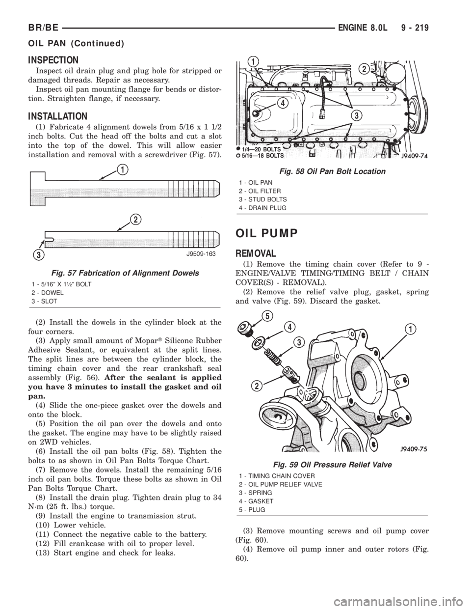
(1) Fabricate 4 alignment dowels from 5/16x11/2
inch bolts. Cut the head off the bolts and cut a slot
into the top of the dowel. This will allow easier
installation and removal with a screwdriver (Fig. 57).
(2) Install the dowels in the cylinder block at the
four corners.
(3) Apply small amount of MopartSilicone Rubber
Adhesive Sealant, or equivalent at the split lines.
The split lines are between the cylinder block, the
timing chain cover and the rear crankshaft seal
assembly (Fig. 56).After the sealant is applied
you have 3 minutes to install the gasket and oil
pan.
(4) Slide the one-piece gasket over the dowels and
onto the block.
(5) Position the oil pan over the dowels and onto
the gasket. The engine may have to be slightly raised
on 2WD vehicles.
(6) Install the oil pan bolts (Fig. 58). Tighten the
bolts to as shown in Oil Pan Bolts Torque Chart.
(7) Remove the dowels. Install the remaining 5/16
inch oil pan bolts. Torque these bolts as shown in Oil
Pan Bolts Torque Chart.
(8) Install the drain plug. Tighten drain plug to 34
N´m (25 ft. lbs.) torque.
(9) Install the engine to transmission strut.
(10) Lower vehicle.
(11) Connect the negative cable to the battery.
(12) Fill crankcase with oil to proper level.
(13) Start engine and check for leaks.
OIL PUMP
REMOVAL
(1) Remove the timing chain cover (Refer to 9 -
ENGINE/VALVE TIMING/TIMING BELT / CHAIN
COVER(S) - REMOVAL).
(2) Remove the relief valve plug, gasket, spring
and valve (Fig. 59). Discard the gasket.
(3) Remove mounting screws and oil pump cover
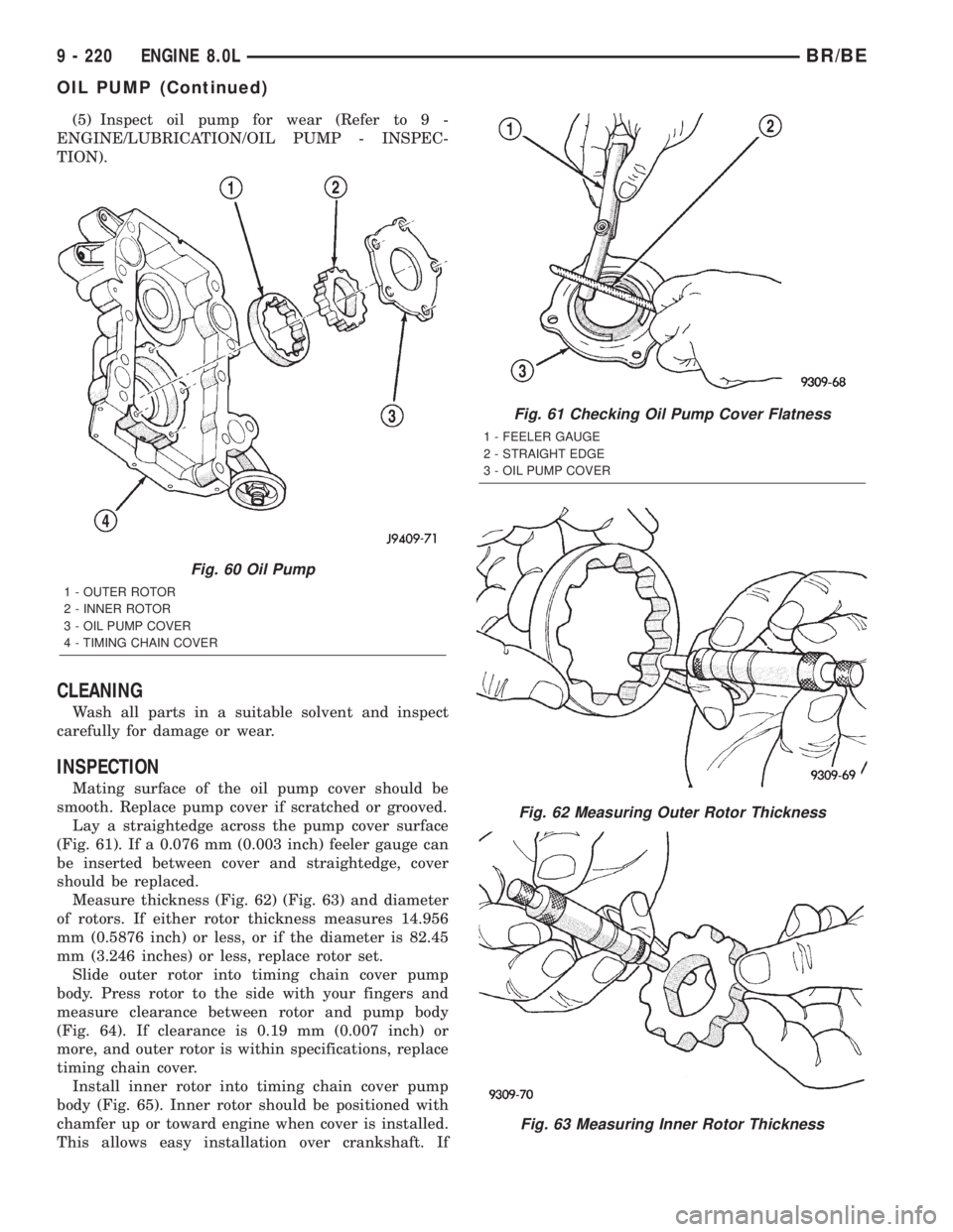
(Fig. 60).
(4) Remove oil pump inner and outer rotors (Fig.
60).
Fig. 57 Fabrication of Alignment Dowels
1 - 5/16º X 1óº BOLT
2 - DOWEL
3 - SLOT
Fig. 58 Oil Pan Bolt Location
1 - OIL PAN
2 - OIL FILTER
3 - STUD BOLTS
4 - DRAIN PLUG
Fig. 59 Oil Pressure Relief Valve
1 - TIMING CHAIN COVER
2 - OIL PUMP RELIEF VALVE
3 - SPRING
4 - GASKET
5 - PLUG
BR/BEENGINE 8.0L 9 - 219
OIL PAN (Continued)
Page 1367 of 2889
(5) Inspect oil pump for wear (Refer to 9 -
ENGINE/LUBRICATION/OIL PUMP - INSPEC-
TION).
CLEANING
Wash all parts in a suitable solvent and inspect
carefully for damage or wear.
INSPECTION
Mating surface of the oil pump cover should be
smooth. Replace pump cover if scratched or grooved.
Lay a straightedge across the pump cover surface
(Fig. 61). If a 0.076 mm (0.003 inch) feeler gauge can
be inserted between cover and straightedge, cover
should be replaced.
Measure thickness (Fig. 62) (Fig. 63) and diameter
of rotors. If either rotor thickness measures 14.956
mm (0.5876 inch) or less, or if the diameter is 82.45
mm (3.246 inches) or less, replace rotor set.
Slide outer rotor into timing chain cover pump
body. Press rotor to the side with your fingers and
measure clearance between rotor and pump body
(Fig. 64). If clearance is 0.19 mm (0.007 inch) or
more, and outer rotor is within specifications, replace
timing chain cover.
Install inner rotor into timing chain cover pump
body (Fig. 65). Inner rotor should be positioned with
chamfer up or toward engine when cover is installed.
This allows easy installation over crankshaft. If
Fig. 60 Oil Pump
1 - OUTER ROTOR
2 - INNER ROTOR
3 - OIL PUMP COVER
4 - TIMING CHAIN COVER
Fig. 61 Checking Oil Pump Cover Flatness
1 - FEELER GAUGE
2 - STRAIGHT EDGE
3 - OIL PUMP COVER
Fig. 62 Measuring Outer Rotor Thickness
Fig. 63 Measuring Inner Rotor Thickness
9 - 220 ENGINE 8.0LBR/BE
OIL PUMP (Continued)
Page 1371 of 2889
(3) Position the cross-over gaskets and press firmly
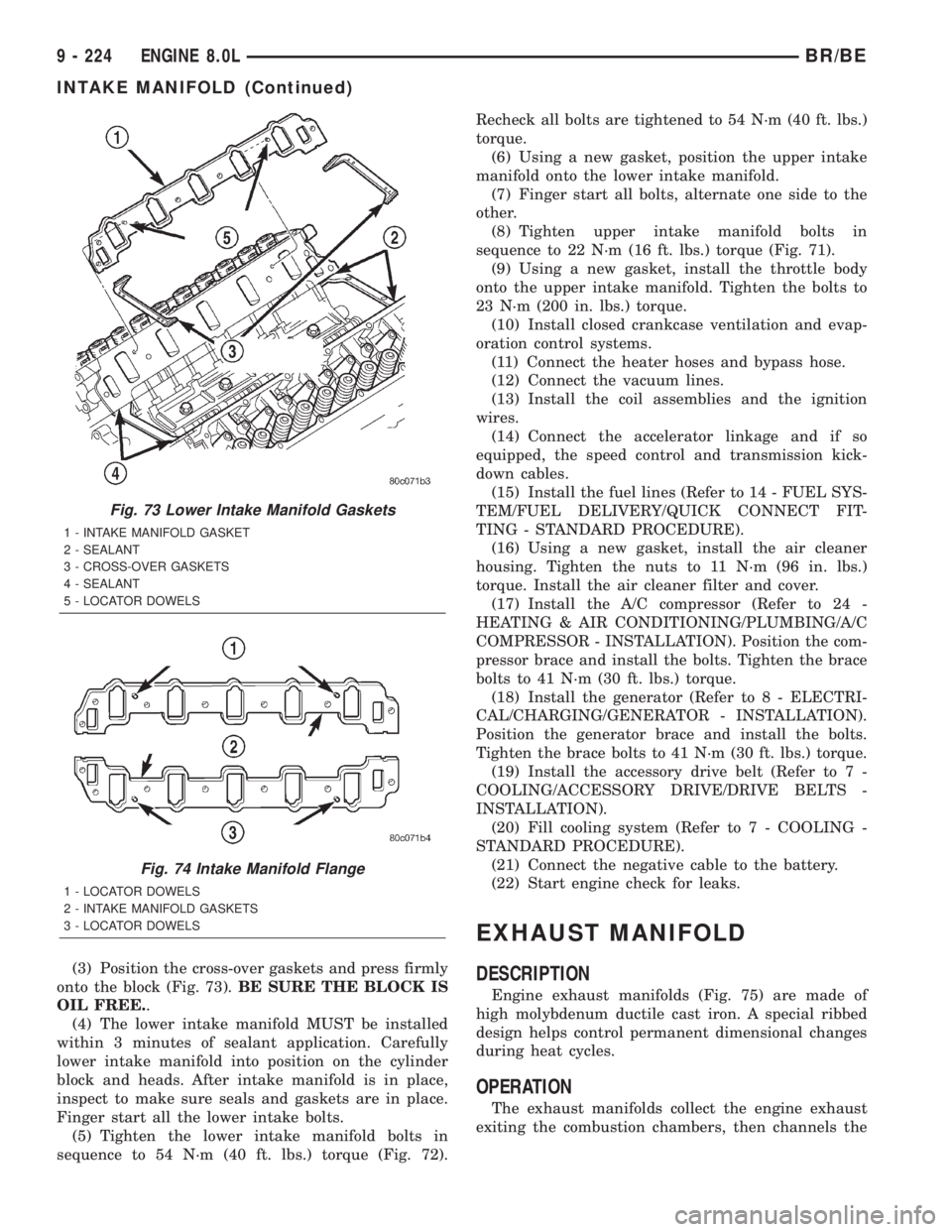
onto the block (Fig. 73).BE SURE THE BLOCK IS
OIL FREE..
(4) The lower intake manifold MUST be installed
within 3 minutes of sealant application. Carefully
lower intake manifold into position on the cylinder
block and heads. After intake manifold is in place,
inspect to make sure seals and gaskets are in place.
Finger start all the lower intake bolts.
(5) Tighten the lower intake manifold bolts in
sequence to 54 N´m (40 ft. lbs.) torque (Fig. 72).Recheck all bolts are tightened to 54 N´m (40 ft. lbs.)
torque.
(6) Using a new gasket, position the upper intake
manifold onto the lower intake manifold.
(7) Finger start all bolts, alternate one side to the
other.
(8) Tighten upper intake manifold bolts in
sequence to 22 N´m (16 ft. lbs.) torque (Fig. 71).
(9) Using a new gasket, install the throttle body
onto the upper intake manifold. Tighten the bolts to
23 N´m (200 in. lbs.) torque.
(10) Install closed crankcase ventilation and evap-
oration control systems.
(11) Connect the heater hoses and bypass hose.
(12) Connect the vacuum lines.
(13) Install the coil assemblies and the ignition
wires.
(14) Connect the accelerator linkage and if so
equipped, the speed control and transmission kick-
down cables.
(15) Install the fuel lines (Refer to 14 - FUEL SYS-
TEM/FUEL DELIVERY/QUICK CONNECT FIT-
TING - STANDARD PROCEDURE).
(16) Using a new gasket, install the air cleaner
housing. Tighten the nuts to 11 N´m (96 in. lbs.)
torque. Install the air cleaner filter and cover.
(17) Install the A/C compressor (Refer to 24 -
HEATING & AIR CONDITIONING/PLUMBING/A/C
COMPRESSOR - INSTALLATION). Position the com-
pressor brace and install the bolts. Tighten the brace
bolts to 41 N´m (30 ft. lbs.) torque.
(18) Install the generator (Refer to 8 - ELECTRI-
CAL/CHARGING/GENERATOR - INSTALLATION).
Position the generator brace and install the bolts.
Tighten the brace bolts to 41 N´m (30 ft. lbs.) torque.
(19) Install the accessory drive belt (Refer to 7 -
COOLING/ACCESSORY DRIVE/DRIVE BELTS -
INSTALLATION).
(20) Fill cooling system (Refer to 7 - COOLING -
STANDARD PROCEDURE).
(21) Connect the negative cable to the battery.
(22) Start engine check for leaks.
EXHAUST MANIFOLD
DESCRIPTION
Engine exhaust manifolds (Fig. 75) are made of
high molybdenum ductile cast iron. A special ribbed
design helps control permanent dimensional changes
during heat cycles.
OPERATION
The exhaust manifolds collect the engine exhaust
exiting the combustion chambers, then channels the
Fig. 73 Lower Intake Manifold Gaskets
1 - INTAKE MANIFOLD GASKET
2 - SEALANT
3 - CROSS-OVER GASKETS
4 - SEALANT
5 - LOCATOR DOWELS
Fig. 74 Intake Manifold Flange
1 - LOCATOR DOWELS
2 - INTAKE MANIFOLD GASKETS
3 - LOCATOR DOWELS
9 - 224 ENGINE 8.0LBR/BE
INTAKE MANIFOLD (Continued)