2001 DODGE RAM brake
[x] Cancel search: brakePage 598 of 2889
LAMPS
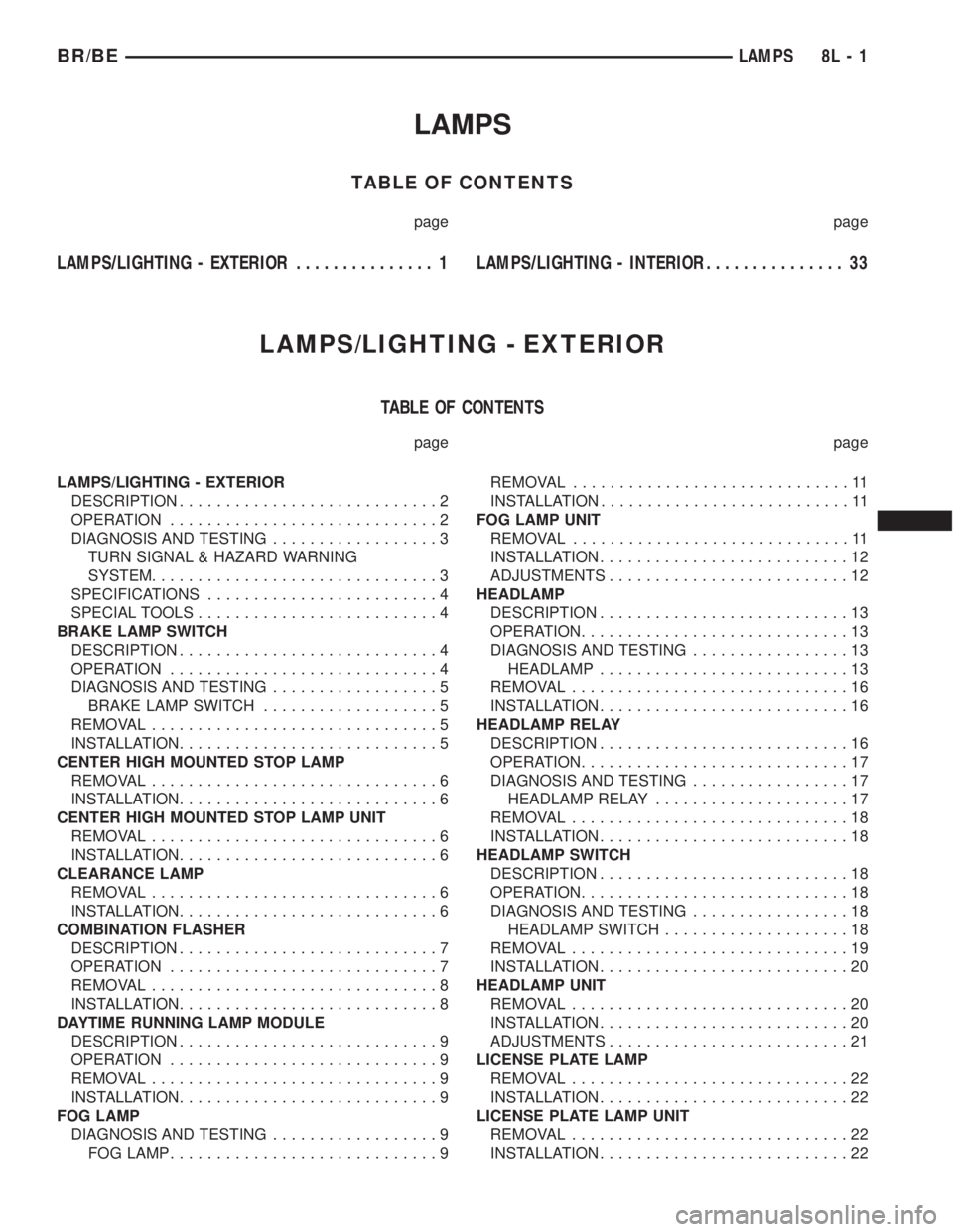
TABLE OF CONTENTS
page page
LAMPS/LIGHTING - EXTERIOR............... 1LAMPS/LIGHTING - INTERIOR............... 33
LAMPS/LIGHTING - EXTERIOR
TABLE OF CONTENTS
page page
LAMPS/LIGHTING - EXTERIOR
DESCRIPTION............................2
OPERATION.............................2
DIAGNOSIS AND TESTING..................3
TURN SIGNAL & HAZARD WARNING
SYSTEM...............................3
SPECIFICATIONS.........................4
SPECIAL TOOLS..........................4
BRAKE LAMP SWITCH
DESCRIPTION............................4
OPERATION.............................4
DIAGNOSIS AND TESTING..................5
BRAKE LAMP SWITCH...................5
REMOVAL...............................5
INSTALLATION............................5
CENTER HIGH MOUNTED STOP LAMP
REMOVAL...............................6
INSTALLATION............................6
CENTER HIGH MOUNTED STOP LAMP UNIT
REMOVAL...............................6
INSTALLATION............................6
CLEARANCE LAMP
REMOVAL...............................6
INSTALLATION............................6
COMBINATION FLASHER
DESCRIPTION............................7
OPERATION.............................7
REMOVAL...............................8
INSTALLATION............................8
DAYTIME RUNNING LAMP MODULE
DESCRIPTION............................9
OPERATION.............................9
REMOVAL...............................9
INSTALLATION............................9
FOG LAMP
DIAGNOSIS AND TESTING..................9
FOG LAMP.............................9REMOVAL..............................11
INSTALLATION...........................11
FOG LAMP UNIT
REMOVAL..............................11
INSTALLATION...........................12
ADJUSTMENTS..........................12
HEADLAMP
DESCRIPTION...........................13
OPERATION.............................13
DIAGNOSIS AND TESTING.................13
HEADLAMP...........................13
REMOVAL..............................16
INSTALLATION...........................16
HEADLAMP RELAY
DESCRIPTION...........................16
OPERATION.............................17
DIAGNOSIS AND TESTING.................17
HEADLAMP RELAY.....................17
REMOVAL..............................18
INSTALLATION...........................18
HEADLAMP SWITCH
DESCRIPTION...........................18
OPERATION.............................18
DIAGNOSIS AND TESTING.................18
HEADLAMP SWITCH....................18
REMOVAL..............................19
INSTALLATION...........................20
HEADLAMP UNIT
REMOVAL..............................20
INSTALLATION...........................20
ADJUSTMENTS..........................21
LICENSE PLATE LAMP
REMOVAL..............................22
INSTALLATION...........................22
LICENSE PLATE LAMP UNIT
REMOVAL..............................22
INSTALLATION...........................22
BR/BELAMPS 8L - 1
Page 601 of 2889
(9) Disconnect the instrument panel wire harness
connector for the multi-function switch from the
switch connector receptacle. Check for continuity
between the hazard flasher signal circuit cavities in
the JB receptacle for the combination flasher and the
instrument panel wire harness connector for the
multi-function switch. There should be continuity. If
OK, go to Step 10. If not OK, repair the open hazard
flasher signal circuit between the JB and the multi-
function switch as required.
(10) Check for continuity between the flasher out-
put circuit cavities of the JB receptacle for the com-
bination flasher and in the instrument panel wire
harness connector for the multi-function switch.
There should be continuity. If OK, test the multi-
function switch. (Refer to 8 - ELECTRICAL/LAMPS/
LIGHTING - EXTERIOR/MULTI-FUNCTION
SWITCH - DIAGNOSIS AND TESTING). If not OK,
repair the open flasher output circuit between the JB
and the multi-function switch as required.
SPECIFICATIONS
EXTERIOR LAMPS
LAMP BULB
Back-up 3157
Cargo 921
Center High Mounted
Stop921
Clearance Roof Mounted 168
Fog Lamps 896
Headlamp - SLT 9004LL
Headlamp - Sport Low
Beam9007
Headlamp - Sport High
Beam9004LL
License Plate w/o
Bumper1155
License Plate -Step
Bumper168
Park/Turn Signal 3157NA
Snow Plow Control 161
Tail/Brake/Turn Signal 3157
Tail/Brake/Cab - Chassis 1157
Underhood 105
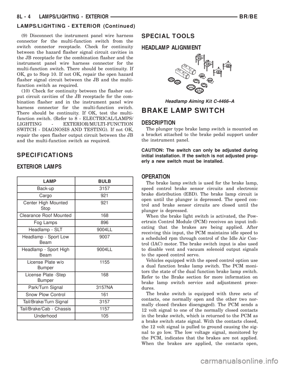
SPECIAL TOOLS
HEADLAMP ALIGNMENT
BRAKE LAMP SWITCH
DESCRIPTION
The plunger type brake lamp switch is mounted on
a bracket attached to the brake pedal support under
the instrument panel.
CAUTION: The switch can only be adjusted during
initial installation. If the switch is not adjusted prop-
erly a new switch must be installed.
OPERATION
The brake lamp switch is used for the brake lamp,
speed control brake sensor circuits and electronic
brake distribution (EBD). The brake lamp circuit is
open until the plunger is depressed. The speed con-
trol and brake sensor circuits are closed until the
plunger is depressed.
When the brake light switch is activated, the Pow-
ertrain Control Module (PCM) receives an input indi-
cating that the brakes are being applied. After
receiving this input, the PCM maintains idle speed to
a scheduled rpm through control of the Idle Air Con-
trol (IAC) motor. The brake switch input is also used
to disable vent and vacuum solenoid output signals
to the speed control servo.
Vehicles equipped with the speed control option use
a dual function brake lamp switch. The PCM moni-
tors the state of the dual function brake lamp switch.
Refer to the Brake section for more information on
brake lamp switch service and adjustment proce-
dures.
The brake switch is equipped with three sets of
contacts, one normally open and the other two nor-
mally closed (brakes disengaged). The PCM sends a
12 volt signal to one of the normally closed contacts
in the brake switch, which is returned to the PCM as
a brake switch state signal. With the contacts closed,
the 12 volt signal is pulled to ground causing the sig-
nal to go low. The low voltage signal, monitored by
the PCM, indicates that the brakes are not applied.
When the brakes are applied, the contacts open,
Headlamp Aiming Kit C-4466±A
8L - 4 LAMPS/LIGHTING - EXTERIORBR/BE
LAMPS/LIGHTING - EXTERIOR (Continued)
Page 602 of 2889
causing the PCM's output brake signal to go high,
disengaging the speed control, cutting off PCM power
to the speed control solenoids.
The second set of normally closed contacts supplies
12 volts from the PCM any time speed control is
turned on. Through the brake switch, current is
routed to the speed control servo solenoids. The
speed control solenoids (vacuum, vent and dump) are
provided this current any time the speed control is
ON and the brakes are disengaged.
When the driver applies the brakes, the contacts
open and current is interrupted to the solenoids. The
normally open contacts are fed battery voltage. When
the brakes are applied, battery voltage is supplied to
the brake lamps.
DIAGNOSIS AND TESTING - BRAKE LAMP
SWITCH
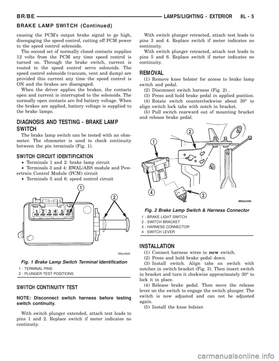
The brake lamp switch can be tested with an ohm-
meter. The ohmmeter is used to check continuity
between the pin terminals (Fig. 1).
SWITCH CIRCUIT IDENTIFICATION
²Terminals 1 and 2: brake lamp circuit
²Terminals 3 and 4: RWAL/ABS module and Pow-
ertrain Control Module (PCM) circuit
²Terminals 5 and 6: speed control circuit
SWITCH CONTINUITY TEST
NOTE: Disconnect switch harness before testing
switch continuity.
With switch plunger extended, attach test leads to
pins 1 and 2. Replace switch if meter indicates no
continuity.With switch plunger retracted, attach test leads to
pins 3 and 4. Replace switch if meter indicates no
continuity.
With switch plunger retracted, attach test leads to
pins 5 and 6. Replace switch if meter indicates no
continuity.
REMOVAL
(1) Remove knee bolster for access to brake lamp
switch and pedal.
(2) Disconnect switch harness (Fig. 2) .
(3) Press and hold brake pedal in applied position.
(4) Rotate switch counterclockwise about 30É to
align switch lock tabs with notch in bracket.
(5) Pull switch rearward out of mounting bracket
and release brake pedal.
INSTALLATION
(1) Connect harness wires tonewswitch.
(2) Press and hold brake pedal down.
(3) Install switch. Align tabs on switch with
notches in switch bracket (Fig. 3). Then insert switch
in bracket and turn it clockwise approximately 30É to
lock it in place.
(4) Release brake pedal. Then move the release
lever on the switch to engage the switch plunger. The
switch is now adjusted and can not be adjusted
again.
(5) Install the knee bolster.
Fig. 1 Brake Lamp Switch Terminal Identification
1 - TERMINAL PINS
2 - PLUNGER TEST POSITIONS
Fig. 2 Brake Lamp Switch & Harness Connector
1 - BRAKE LIGHT SWITCH
2 - SWITCH BRACKET
3 - HARNESS CONNECTOR
4 - SWITCH LEVER
BR/BELAMPS/LIGHTING - EXTERIOR 8L - 5
BRAKE LAMP SWITCH (Continued)
Page 603 of 2889
CENTER HIGH MOUNTED
STOP LAMP
REMOVAL
(1) Disconnect and isolate the battery negative
cable.
(2) Remove the CHMSL from the roof panel.
(3) Rotate sockets 1/4 turn clockwise and remove
from lamp. (The two center bulbs light the stoplamp
and the outside bulbs light the cargo lamp, if
equipped.)
(4) Pull bulb from socket.
INSTALLATION
(1) Push bulb into socket.
(2) Position socket in lamp an rotate socket 1/4
turn counterclockwise.
(3) Install the CHMSL.
(4) Connect the battery negative cable.
CENTER HIGH MOUNTED
STOP LAMP UNIT
REMOVAL
(1) Disconnect and isolate the battery negative
cable.
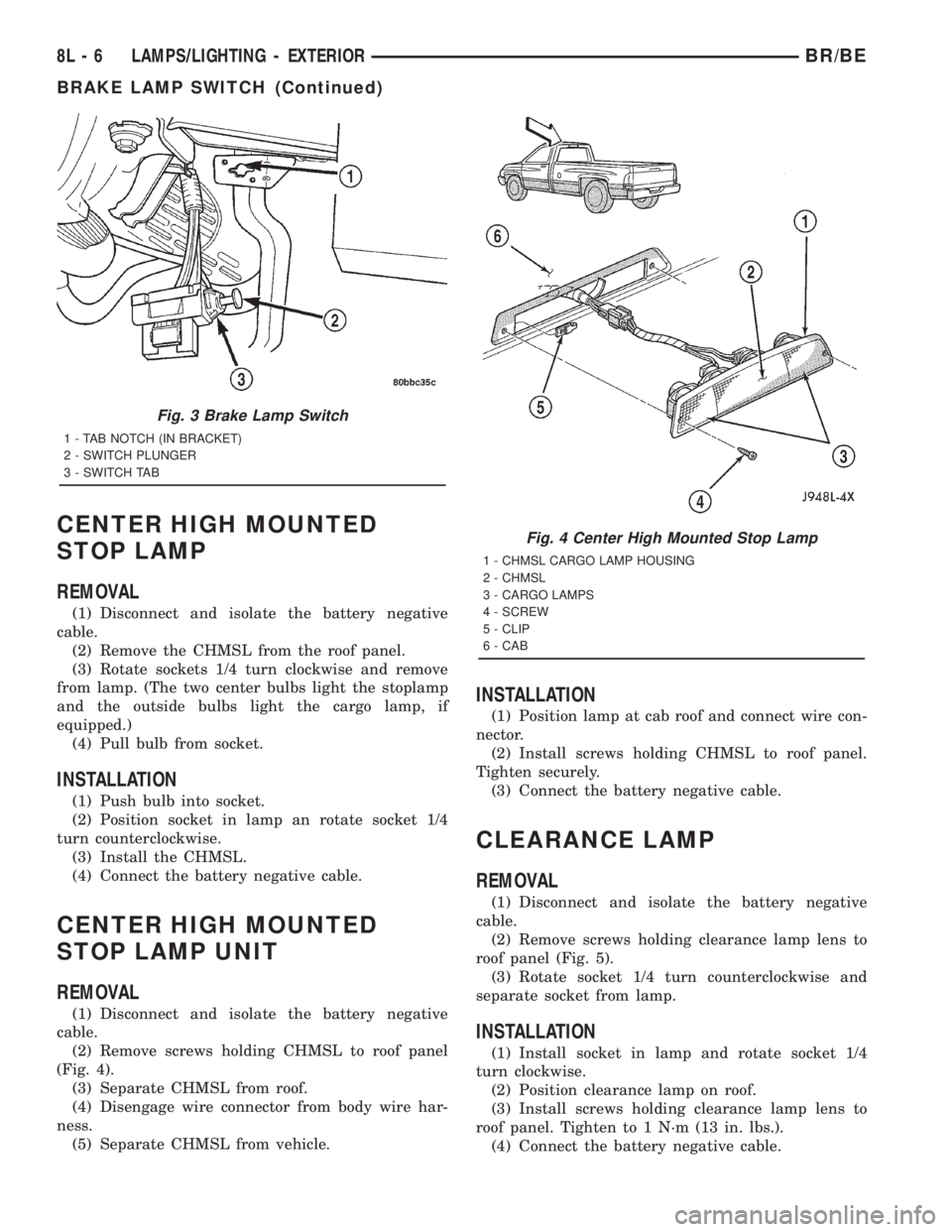
(2) Remove screws holding CHMSL to roof panel
(Fig. 4).
(3) Separate CHMSL from roof.
(4) Disengage wire connector from body wire har-
ness.
(5) Separate CHMSL from vehicle.
INSTALLATION
(1) Position lamp at cab roof and connect wire con-
nector.
(2) Install screws holding CHMSL to roof panel.
Tighten securely.
(3) Connect the battery negative cable.
CLEARANCE LAMP
REMOVAL
(1) Disconnect and isolate the battery negative
cable.
(2) Remove screws holding clearance lamp lens to
roof panel (Fig. 5).
(3) Rotate socket 1/4 turn counterclockwise and
separate socket from lamp.
INSTALLATION
(1) Install socket in lamp and rotate socket 1/4
turn clockwise.
(2) Position clearance lamp on roof.
(3) Install screws holding clearance lamp lens to
roof panel. Tighten to 1 N´m (13 in. lbs.).
(4) Connect the battery negative cable.
Fig. 3 Brake Lamp Switch
1 - TAB NOTCH (IN BRACKET)
2 - SWITCH PLUNGER
3 - SWITCH TAB
Fig. 4 Center High Mounted Stop Lamp
1 - CHMSL CARGO LAMP HOUSING
2 - CHMSL
3 - CARGO LAMPS
4 - SCREW
5 - CLIP
6 - CAB
8L - 6 LAMPS/LIGHTING - EXTERIORBR/BE
BRAKE LAMP SWITCH (Continued)
Page 627 of 2889
(3) Separate lens from lamp.
(4) Grasp bulb, push in slightly and rotate 1/2 turn
counter-clockwise.
PICKUP
(1) Disconnect and isolate the battery negative
cable.
(2) Remove screws from tail lamp.
(3) Grasp lamp, firmly pull lamp rearward to dis-
engage retaining studs.
(4) Remove socket from tail lamp.
(5) Separate tail lamp from cargo box.
(6) Pull bulb from socket.
INSTALLATION
CHASSIS CAB
(1) Install bulb in socket.
(2) Install lamp lens.
(3) Connect the battery negative cable.
PICKUP
(1) Install bulb in socket.
(2) Install socket in tail lamp.
(3) Position tail lamp in cargo box, engage retain-
ing studs and install screws.
(4) Connect the battery negative cable.
TAIL LAMP UNIT
REMOVAL
CAB CHASSIS
(1) Disconnect and isolate the battery negative
cable.
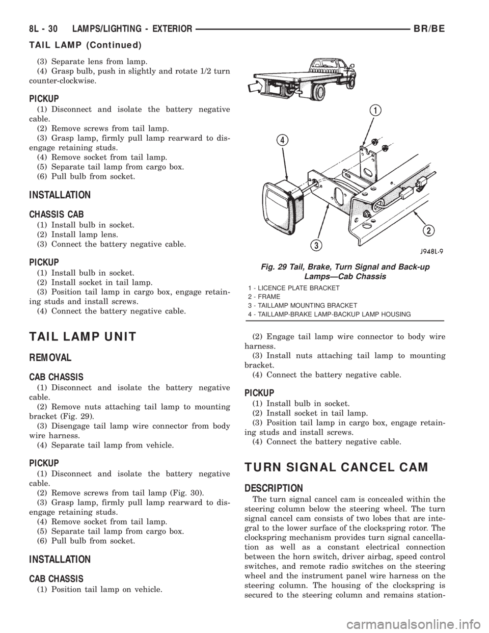
(2) Remove nuts attaching tail lamp to mounting
bracket (Fig. 29).
(3) Disengage tail lamp wire connector from body
wire harness.
(4) Separate tail lamp from vehicle.
PICKUP
(1) Disconnect and isolate the battery negative
cable.
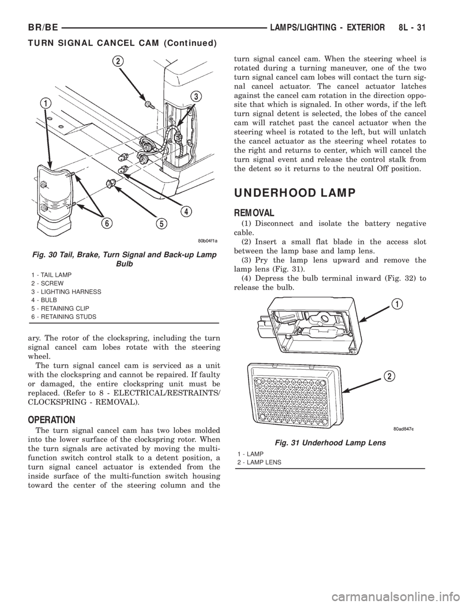
(2) Remove screws from tail lamp (Fig. 30).
(3) Grasp lamp, firmly pull lamp rearward to dis-
engage retaining studs.
(4) Remove socket from tail lamp.
(5) Separate tail lamp from cargo box.
(6) Pull bulb from socket.
INSTALLATION
CAB CHASSIS
(1) Position tail lamp on vehicle.(2) Engage tail lamp wire connector to body wire
harness.
(3) Install nuts attaching tail lamp to mounting
bracket.
(4) Connect the battery negative cable.
PICKUP
(1) Install bulb in socket.
(2) Install socket in tail lamp.
(3) Position tail lamp in cargo box, engage retain-
ing studs and install screws.
(4) Connect the battery negative cable.
TURN SIGNAL CANCEL CAM
DESCRIPTION
The turn signal cancel cam is concealed within the
steering column below the steering wheel. The turn
signal cancel cam consists of two lobes that are inte-
gral to the lower surface of the clockspring rotor. The
clockspring mechanism provides turn signal cancella-
tion as well as a constant electrical connection
between the horn switch, driver airbag, speed control
switches, and remote radio switches on the steering
wheel and the instrument panel wire harness on the
steering column. The housing of the clockspring is
secured to the steering column and remains station-
Fig. 29 Tail, Brake, Turn Signal and Back-up
LampsÐCab Chassis
1 - LICENCE PLATE BRACKET
2 - FRAME
3 - TAILLAMP MOUNTING BRACKET
4 - TAILLAMP-BRAKE LAMP-BACKUP LAMP HOUSING
8L - 30 LAMPS/LIGHTING - EXTERIORBR/BE
TAIL LAMP (Continued)
Page 628 of 2889
ary. The rotor of the clockspring, including the turn
signal cancel cam lobes rotate with the steering
wheel.
The turn signal cancel cam is serviced as a unit
with the clockspring and cannot be repaired. If faulty
or damaged, the entire clockspring unit must be
replaced. (Refer to 8 - ELECTRICAL/RESTRAINTS/
CLOCKSPRING - REMOVAL).
OPERATION
The turn signal cancel cam has two lobes molded
into the lower surface of the clockspring rotor. When
the turn signals are activated by moving the multi-
function switch control stalk to a detent position, a
turn signal cancel actuator is extended from the
inside surface of the multi-function switch housing
toward the center of the steering column and theturn signal cancel cam. When the steering wheel is
rotated during a turning maneuver, one of the two
turn signal cancel cam lobes will contact the turn sig-
nal cancel actuator. The cancel actuator latches
against the cancel cam rotation in the direction oppo-
site that which is signaled. In other words, if the left
turn signal detent is selected, the lobes of the cancel
cam will ratchet past the cancel actuator when the
steering wheel is rotated to the left, but will unlatch
the cancel actuator as the steering wheel rotates to
the right and returns to center, which will cancel the
turn signal event and release the control stalk from
the detent so it returns to the neutral Off position.
UNDERHOOD LAMP
REMOVAL
(1) Disconnect and isolate the battery negative
cable.
(2) Insert a small flat blade in the access slot
between the lamp base and lamp lens.
(3) Pry the lamp lens upward and remove the
lamp lens (Fig. 31).
(4) Depress the bulb terminal inward (Fig. 32) to
release the bulb.
Fig. 30 Tail, Brake, Turn Signal and Back-up Lamp
Bulb
1 - TAIL LAMP
2 - SCREW
3 - LIGHTING HARNESS
4 - BULB
5 - RETAINING CLIP
6 - RETAINING STUDS
Fig. 31 Underhood Lamp Lens
1 - LAMP
2 - LAMP LENS
BR/BELAMPS/LIGHTING - EXTERIOR 8L - 31
TURN SIGNAL CANCEL CAM (Continued)
Page 630 of 2889
LAMPS/LIGHTING - INTERIOR
TABLE OF CONTENTS
page page
LAMPS/LIGHTING - INTERIOR
SPECIFICATIONS........................33
DOME LAMP
REMOVAL..............................33
INSTALLATION...........................33
DOOR AJAR SWITCH
DESCRIPTION...........................34
DIAGNOSIS AND TESTING.................34
DOOR AJAR SWITCH....................34
REMOVAL..............................35
INSTALLATION...........................35GLOVE BOX LAMP AND SWITCH
REMOVAL..............................35
INSTALLATION...........................35
READING LAMP
DESCRIPTION...........................36
OPERATION.............................36
REMOVAL..............................36
INSTALLATION...........................36
VANITY LAMP
REMOVAL..............................37
INSTALLATION...........................37
LAMPS/LIGHTING - INTERIOR
SPECIFICATIONS
INTERIOR LAMPS
LAMP BULB
A/C HEATER CONTROL 158
ASH RECEIVER 161
CIGAR LIGHTER 161
HEADLAMP SWITCH 158
HEATER CONTROL 158
INSTRUMENT CLUSTER PC194
RADIO ASC
AIRBAG HIGH LINE PC194
AIRBAG LOW LINE PC74
ANTI-LOCK BRAKE PC74
BATTERY VOLTAGE PC194
BRAKE WARNING PC194
CHECK ENGINE PC74
ENGINE OIL PRESSURE PC74
FOUR WHEEL DRIVE PC194
HIGH BEAM PC194
LOW FUEL PC194
LOW WASHER FLUID PC74
MAINTENANCE
REQUIREDPC74
MESSAGE CENTER PC194
SEAT BELT PC74
LAMP BULB
TURN SIGNAL PC194
UPSHIFT PC74
DOME 1004
GLOVE COMPARTMENT 1891
VANITY MIRROR LAMP P/N 6501966
DOME LAMP
REMOVAL
(1) Using a small flat blade, pry the left side (driv-
er's side) of the dome lamp lens downward from
dome lamp.
(2) Allow the lens to hang down (Fig. 1) , this will
disengage the right side of the lamp (passenger's
side) from the headliner.
(3) Pull the right side of the lamp down and slide
the lamp to the right (Fig. 2) .
(4) Separate the lamp from the headliner.
(5) Disengage dome lamp wire connector from body
wire harness.
(6) Separate dome lamp from vehicle.
INSTALLATION
(1) Position dome lamp at headliner.
(2) Connect dome lamp wire connector to body
wire harness.
(3) Position the left side of the lamp in the head-
liner opening and slide lamp to the left.
(4) Push the right side of the lamp in the head-
liner opening and push the lamp lens up into the
lamp to secure.
BR/BELAMPS/LIGHTING - INTERIOR 8L - 33
Page 660 of 2889

OPERATION
The ambient photocell sensor is located on the for-
ward-facing (windshield side) of the rear view mirror
housing, and detects the ambient light levels outside
of the vehicle. The headlamp photocell sensor is
located inside the rear view mirror housing behind
the mirror glass and faces rearward, to detect the
level of the light being received at the rear window
side of the mirror. When the circuitry of the auto-
matic day/night mirror detects that the difference
between the two light levels is too great (the light
level received at the rear of the mirror is much
higher than that at the front of the mirror), it begins
to darken the mirror.
The automatic day/night mirror circuitry also mon-
itors the transmission using an input from the
backup lamp circuit. The mirror circuitry is pro-
grammed to automatically disable its self-dimming
feature whenever it senses that the transmission
backup lamp circuit is energized.
The automatic day/night mirror is a completely
self-contained unit and cannot be repaired. If faulty
or damaged, the entire mirror assembly must be
replaced.
DIAGNOSIS AND TESTING - AUTOMATIC
DAY/NIGHT MIRROR
For circuit descriptions and diagrams, refer to the
appropriate wiring information. The wiring informa-
tion includes wiring diagrams, proper wire and con-
nector repair procedures, details of wire harness
routing and retention, connector pin-out information
and location views for the various wire harness con-
nectors, splices and grounds.
(1) Check the fuse in the junction block. If OK, go
to Step 2. If not OK, repair the shorted circuit or
component as required replace the faulty fuse.
(2) Turn the ignition switch to the On position.
Check for battery voltage at the fuse in the junction
block. If OK, go to Step 3. If not OK, repair the open
circuit to the ignition switch as required.
(3) Turn the ignition switch to the Off position.
Disconnect and isolate the battery negative cable.
Unplug the wire harness connector from the auto-
matic day/night mirror (Fig. 1). Connect the battery
negative cable. Turn the ignition switch to the On
position. Check for battery voltage at the fused igni-
tion switch output (run/start) circuit cavity of the
automatic day/night mirror wire harness connector. If
OK, go to Step 4. If not OK, repair the open circuit to
the junction block as required.
(4) Turn the ignition switch to the Off position.
Disconnect and isolate the battery negative cable.
Check for continuity between the ground circuit cav-
ity of the automatic day/night mirror wire harness
connector and a good ground. There should be conti-nuity. If OK, go to Step 5. If not OK, repair the cir-
cuit to ground as required.
(5) Connect the battery negative cable. Turn the
ignition switch to the On position. Set the parking
brake. Place the transmission gear selector lever in
the Reverse position. Check for battery voltage at the
backup lamp switch output circuit cavity of the auto-
matic day/night mirror wire harness connector. If
OK, go to Step 6. If not OK, repair the open circuit
as required.
(6) Turn the ignition switch to the Off position.
Disconnect the battery negative cable. Plug in the
automatic day/night mirror wire harness connector.
Connect the battery negative cable. Turn the ignition
switch to the On position. Place the transmission
gear selector lever in the Neutral position. Place the
mirror switch in the On (LED in the mirror switch is
lighted) position. Cover the forward facing ambient
photocell sensor to keep out any ambient light.
NOTE: The ambient photocell sensor must be cov-
ered completely, so that no light reaches the sen-
sor. Use a finger pressed tightly against the sensor,
or cover the sensor completely with electrical tape.
(7) Shine a light into the rearward facing head-
lamp photocell sensor. The mirror glass should
darken. If OK, go to Step 8. If not OK, replace the
faulty automatic day/night mirror unit.
(8) With the mirror glass darkened, place the
transmission gear selector lever in the Reverse posi-
tion. The mirror should return to its normal reflec-
tance. If not OK, replace the faulty automatic day/
night mirror unit.
Fig. 1 Automatic Day/Night Mirror
BR/BEPOWER MIRRORS 8N - 11
AUTOMATIC DAY / NIGHT MIRROR (Continued)