2001 DODGE RAM brake
[x] Cancel search: brakePage 452 of 2889
ELECTRONIC CONTROL MODULES
TABLE OF CONTENTS
page page
BODY CONTROL/CENTRAL TIMER MODULE
DESCRIPTION............................1
OPERATION.............................3
DIAGNOSIS AND TESTING..................4
CENTRAL TIMER MODULE................4
REMOVAL...............................5
INSTALLATION............................6
COMMUNICATION
DESCRIPTION............................6
OPERATION.............................7
DIAGNOSIS AND TESTING.................11
CCDDATABUS ........................11
CONTROLLER ANTILOCK BRAKE
DESCRIPTION...........................11
OPERATION.............................11REMOVAL..............................12
INSTALLATION...........................12
DATA LINK CONNECTOR
DESCRIPTION...........................12
OPERATION.............................12
ENGINE CONTROL MODULE
DESCRIPTION...........................13
OPERATION.............................13
REMOVAL..............................14
INSTALLATION...........................14
POWERTRAIN CONTROL MODULE
DESCRIPTION...........................14
OPERATION.............................17
REMOVAL..............................19
INSTALLATION...........................20
BODY CONTROL/CENTRAL
TIMER MODULE
DESCRIPTION
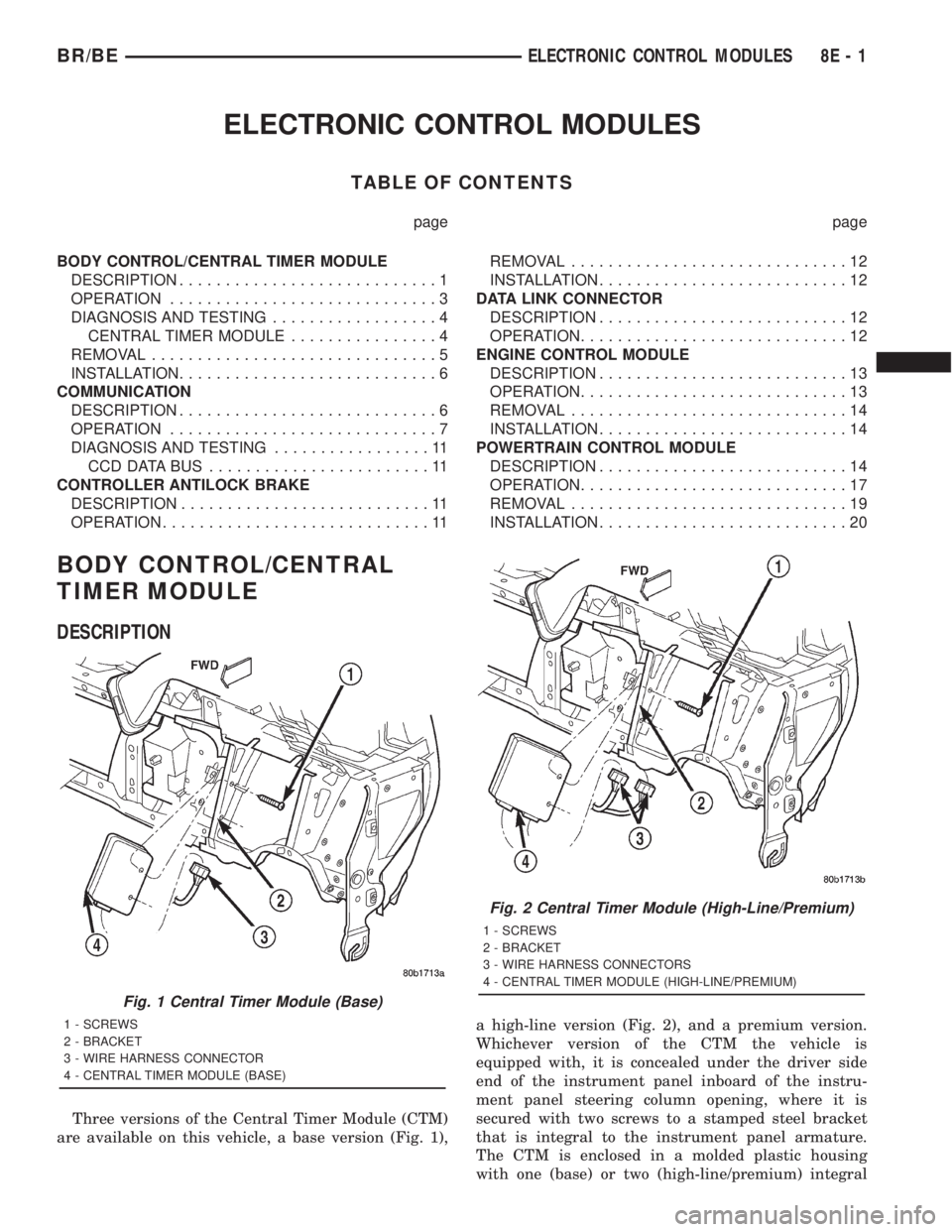
Three versions of the Central Timer Module (CTM)
are available on this vehicle, a base version (Fig. 1),a high-line version (Fig. 2), and a premium version.
Whichever version of the CTM the vehicle is
equipped with, it is concealed under the driver side
end of the instrument panel inboard of the instru-
ment panel steering column opening, where it is
secured with two screws to a stamped steel bracket
that is integral to the instrument panel armature.
The CTM is enclosed in a molded plastic housing
with one (base) or two (high-line/premium) integral
Fig. 1 Central Timer Module (Base)
1 - SCREWS
2 - BRACKET
3 - WIRE HARNESS CONNECTOR
4 - CENTRAL TIMER MODULE (BASE)
Fig. 2 Central Timer Module (High-Line/Premium)
1 - SCREWS
2 - BRACKET
3 - WIRE HARNESS CONNECTORS
4 - CENTRAL TIMER MODULE (HIGH-LINE/PREMIUM)
BR/BEELECTRONIC CONTROL MODULES 8E - 1
Page 462 of 2889

the module attempts to have the CCD chip re-send
the message.
DIAGNOSIS AND TESTING - CCD DATA BUS
CCD BUS FAILURE
The CCD data bus can be monitored using the
DRBIIItscan tool. However, it is possible for the
data bus to pass all tests since the voltage parame-
ters will be in ªrangeª and false signals are being
sent. There are essentially 12 ªhard failuresª that
can occur with the CCD data bus:
²Bus Shorted to Battery
²Bus Shorted to 5 Volts
²Bus Shorted to Ground
²Bus (+) Shorted to Bus (±)
²Bus (±) and Bus (+) Open
²Bus (+) Open
²Bus (±) Open
²No Bus Bias
²Bus Bias Level Too High
²Bus Bias Level Too Low
²No Bus Termination
²Not Receiving Bus Messages Correctly
Refer to the appropriate diagnostic procedures for
details on how to diagnose these faults using a
DRBIIItscan tool.
BUS FAILURE VISUAL SYMPTOM DIAGNOSIS
The following visible symptoms or customer com-
plaints, alone or in combination, may indicate a CCD
data bus failure:
²Airbag Indicator Lamp and Malfuntion Indicator
Lamp (MIL) Illuminated
²Instrument Cluster Gauges (All) Inoperative
²No Compass Mini-Trip Computer (CMTC) Oper-
ation
CONTROLLER ANTILOCK
BRAKE
DESCRIPTION
The Controller Antilock Brakes (CAB) is a micro-
processor which handles testing, monitoring and con-
trolling the ABS brake system operation (Fig. 10).
The CAB functions are:
²Perform self-test diagnostics.
²Monitor the RWAL brake system for proper oper-
ation.
²Control the RWAL valve solenoids.
NOTE: If the CAB needs to be replaced, the rear
axle type and tire revolutions per mile must be pro-
gramed into the new CAB. For axle type refer to
Group 3 Differential and Driveline. For tire revolu-tions per mile,(Refer to 22 - TIRES/WHEELS/TIRES -
SPECIFICATIONS) . To program the CAB refer to the
Chassis Diagnostic Manual.
OPERATION
SYSTEM SELF-TEST
When the ignition switch is turned-on the micro-
processor RAM and ROM are tested. If an error
occurs during the test, a DTC will be set into the
RAM memory. However it is possible the DTC will
not be stored in memory if the error has occurred in
the RAM module were the DTC's are stored. Also it
is possible a DTC may not be stored if the error has
occurred in the ROM which signals the RAM to store
the DTC.
CAB INPUTS
The CAB continuously monitors the speed of the
differential ring gear by monitoring signals generated
by the rear wheel speed sensor. The CAB determines
a wheel locking tendency when it recognizes the ring
gear is decelerating too rapidly. The CAB monitors
the following inputs to determine when a wheel lock-
ing tendency may exists:
²Rear Wheel Speed Sensor
²Brake Lamp Switch
²Brake Warning Lamp Switch
²Reset Switch
²4WD Switch (If equipped)
CAB OUTPUTS
The CAB controls the following outputs for antilock
braking and brake warning information:
²RWAL Valve
Fig. 10 RWAL CAB
1-RWALCAB
BR/BEELECTRONIC CONTROL MODULES 8E - 11
COMMUNICATION (Continued)
Page 463 of 2889
²ABS Warning Lamp
²Brake Warning Lamp
REMOVAL
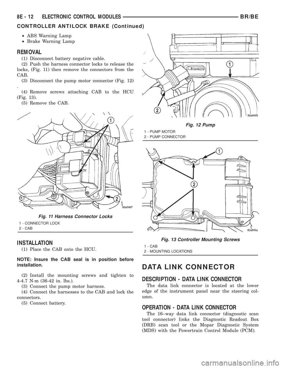
(1) Disconnect battery negative cable.
(2) Push the harness connector locks to release the
locks, (Fig. 11) then remove the connectors from the
CAB.
(3) Disconnect the pump motor connector (Fig. 12)
.
(4) Remove screws attaching CAB to the HCU
(Fig. 13).
(5) Remove the CAB.
INSTALLATION
(1) Place the CAB onto the HCU.
NOTE: Insure the CAB seal is in position before
installation.
(2) Install the mounting screws and tighten to
4-4.7 N´m (36-42 in. lbs.).
(3) Connect the pump motor harness.
(4) Connect the harnesses to the CAB and lock the
connectors.
(5) Connect battery.
DATA LINK CONNECTOR
DESCRIPTION - DATA LINK CONNECTOR
The data link connector is located at the lower
edge of the instrument panel near the steering col-
umn.
OPERATION - DATA LINK CONNECTOR
The 16±way data link connector (diagnostic scan
tool connector) links the Diagnostic Readout Box
(DRB) scan tool or the Mopar Diagnostic System
(MDS) with the Powertrain Control Module (PCM).
Fig. 11 Harness Connector Locks
1 - CONNECTOR LOCK
2 - CAB
Fig. 12 Pump
1 - PUMP MOTOR
2 - PUMP CONNECTOR
Fig. 13 Controller Mounting Screws
1 - CAB
2 - MOUNTING LOCATIONS
8E - 12 ELECTRONIC CONTROL MODULESBR/BE
CONTROLLER ANTILOCK BRAKE (Continued)
Page 468 of 2889

²Camshaft position sensor signal (in the distribu-
tor)
²Park/neutral switch (gear indicator signalÐauto.
trans. only)
²Vehicle speed sensor
If the vehicle is under hard deceleration with the
proper rpm and closed throttle conditions, the PCM
will ignore the oxygen sensor input signal. The PCM
will enter a fuel cut-off strategy in which it will not
supply a ground to the injectors. If a hard decelera-
tion does not exist, the PCM will determine the
proper injector pulse width and continue injection.
Based on the above inputs, the PCM will adjust
engine idle speed through the idle air control (IAC)
motor.
The PCM adjusts ignition timing by turning the
ground path to the coil on and off.
WIDE OPEN THROTTLE MODE
This is an Open Loop mode. During wide open
throttle operation, the PCM receives the following
inputs.
²Battery voltage
²Crankshaft position sensor
²Engine coolant temperature sensor
²Intake manifold air temperature sensor
²Manifold absolute pressure (MAP) sensor
²Throttle position sensor (TPS)
²Camshaft position sensor signal (in the distribu-
tor)
During wide open throttle conditions, the following
occurs:
²Voltage is applied to the fuel injectors with the
ASD relay via the PCM. The PCM will then control
the injection sequence and injector pulse width by
turning the ground circuit to each individual injector
on and off. The PCM ignores the oxygen sensor input
signal and provides a predetermined amount of addi-
tional fuel. This is done by adjusting injector pulse
width.
²The PCM adjusts ignition timing by turning the
ground path to the coil on and off.
IGNITION SWITCH OFF MODE
When ignition switch is turned to OFF position,
the PCM stops operating the injectors, ignition coil,
ASD relay and fuel pump relay.
DESCRIPTION - 5 VOLT SUPPLIES
Two different Powertrain Control Module (PCM)
five volt supply circuits are used; primary and sec-
ondary.
DESCRIPTION - IGNITION CIRCUIT SENSE
This circuit ties the ignition switch to the Power-
train Control Module (PCM).
DESCRIPTION - POWER GROUNDS
The Powertrain Control Module (PCM) has 2 main
grounds. Both of these grounds are referred to as
power grounds. All of the high-current, noisy, electri-
cal devices are connected to these grounds as well as
all of the sensor returns. The sensor return comes
into the sensor return circuit, passes through noise
suppression, and is then connected to the power
ground.
The power ground is used to control ground cir-
cuits for the following PCM loads:
²Generator field winding
²Fuel injectors
²Ignition coil(s)
²Certain relays/solenoids
²Certain sensors
DESCRIPTION - SENSOR RETURN
The Sensor Return circuits are internal to the Pow-
ertrain Control Module (PCM).
Sensor Return provides a low±noise ground refer-
ence for all engine control system sensors. Refer to
Power Grounds for more information.
DESCRIPTION - SIGNAL GROUND
Signal ground provides a low noise ground to the
data link connector.
OPERATION - PCM - GAS ENGINES
The PCM operates the fuel system. The PCM is a
pre-programmed, triple microprocessor digital com-
puter. It regulates ignition timing, air-fuel ratio,
emission control devices, charging system, certain
transmission features, speed control, air conditioning
compressor clutch engagement and idle speed. The
PCM can adapt its programming to meet changing
operating conditions.
The PCM receives input signals from various
switches and sensors. Based on these inputs, the
PCM regulates various engine and vehicle operations
through different system components. These compo-
nents are referred to as Powertrain Control Module
(PCM) Outputs. The sensors and switches that pro-
vide inputs to the PCM are considered Powertrain
Control Module (PCM) Inputs.
The PCM adjusts ignition timing based upon
inputs it receives from sensors that react to: engine
rpm, manifold absolute pressure, engine coolant tem-
perature, throttle position, transmission gear selec-
tion (automatic transmission), vehicle speed and the
brake switch.
The PCM adjusts idle speed based on inputs it
receives from sensors that react to: throttle position,
vehicle speed, transmission gear selection, engine
coolant temperature and from inputs it receives from
the air conditioning clutch switch and brake switch.
BR/BEELECTRONIC CONTROL MODULES 8E - 17
POWERTRAIN CONTROL MODULE (Continued)
Page 469 of 2889

Based on inputs that it receives, the PCM adjusts
ignition coil dwell. The PCM also adjusts the gener-
ator charge rate through control of the generator
field and provides speed control operation.
NOTE: PCM Inputs:
²A/C request (if equipped with factory A/C)
²A/C select (if equipped with factory A/C)
²Auto shutdown (ASD) sense
²Battery temperature
²Battery voltage
²Brake switch
²CCD bus (+) circuits
²CCD bus (-) circuits
²Camshaft position sensor signal
²Crankshaft position sensor
²Data link connection for DRB scan tool
²Engine coolant temperature sensor
²Fuel level
²Generator (battery voltage) output
²Ignition circuit sense (ignition switch in on/off/
crank/run position)
²Intake manifold air temperature sensor
²Leak detection pump (switch) sense (if equipped)
²Manifold absolute pressure (MAP) sensor
²Oil pressure
²Output shaft speed sensor
²Overdrive/override switch
²Oxygen sensors
²Park/neutral switch (auto. trans. only)
²Power ground
²Sensor return
²Signal ground
²Speed control multiplexed single wire input
²Throttle position sensor
²Transmission governor pressure sensor
²Transmission temperature sensor
²Vehicle speed inputs from ABS or RWAL system
NOTE: PCM Outputs:
²A/C clutch relay
²Auto shutdown (ASD) relay
²CCD bus (+/-) circuits for: speedometer, voltme-
ter, fuel gauge, oil pressure gauge/lamp, engine temp.
gauge and speed control warn. lamp
²Data link connection for DRB scan tool
²EGR valve control solenoid (if equipped)
²EVAP canister purge solenoid
²Five volt sensor supply (primary)
²Five volt sensor supply (secondary)
²Fuel injectors
²Fuel pump relay
²Generator field driver (-)
²Generator field driver (+)
²Generator lamp (if equipped)²Idle air control (IAC) motor
²Ignition coil
²Leak detection pump (if equipped)
²Malfunction indicator lamp (Check engine lamp).
Driven through CCD circuits.
²Overdrive indicator lamp (if equipped)
²Service Reminder Indicator (SRI) Lamp (MAINT
REQ'D lamp). Driven through CCD circuits.
²Speed control vacuum solenoid
²Speed control vent solenoid
²Tachometer (if equipped). Driven through CCD
circuits.
²Transmission convertor clutch circuit
²Transmission 3±4 shift solenoid
²Transmission relay
²Transmission temperature lamp (if equipped)
²Transmission variable force solenoid
OPERATION - DIESEL
Two different control modules are used: The Pow-
ertrain Control Module (PCM), and the Engine Con-
trol Module (ECM). The ECMcontrolsthe fuel
system. The PCMdoes not controlthe fuel system.
The PCM's main function is to control: the vehicle
charging system, speed control system, transmission,
air conditioning system and certain bussed messages.
The PCM can adapt its programming to meet
changing operating conditions.
The PCM receives input signals from various
switches and sensors. Based on these inputs, the
PCM regulates various engine and vehicle operations
through different system components. These compo-
nents are referred to asPCM Outputs.The sensors
and switches that provide inputs to the PCM are con-
sideredPCM Inputs.
NOTE: PCM Inputs:
²A/C request (if equipped with factory A/C)
²A/C select (if equipped with factory A/C)
²Accelerator Pedal Position Sensor (APPS) output
from ECM
²Auto shutdown (ASD) relay sense
²Battery temperature sensor
²Battery voltage
²Brake switch
²CCD bus (+) circuits
²CCD bus (-) circuits
²Crankshaft Position Sensor (CKP) output from
ECM
²Data link connection for DRB scan tool
²Fuel level sensor
²Generator (battery voltage) output
²Ignition sense
²Output shaft speed sensor
²Overdrive/override switch
²Park/neutral switch (auto. trans. only)
8E - 18 ELECTRONIC CONTROL MODULESBR/BE
POWERTRAIN CONTROL MODULE (Continued)
Page 492 of 2889
rosion or foreign material, then reassembled.
Following reassembly, check the voltage drop for the
battery cable connection and the battery cable again
to confirm repair.
When performing the voltage drop test, it is impor-
tant to remember that the voltage drop is giving an
indication of the resistance between the two points at
which the voltmeter probes are attached.EXAM-
PLE:When testing the resistance of the battery pos-
itive cable, touch the voltmeter leads to the battery
positive cable terminal clamp and to the battery pos-
itive cable eyelet terminal at the starter solenoid
B(+) terminal stud. If you probe the battery positive
terminal post and the battery positive cable eyelet
terminal at the starter solenoid B(+) terminal stud,
you are reading the combined voltage drop in the
battery positive cable terminal clamp-to-terminal
post connection and the battery positive cable.
VOLTAGE DROP TEST
WARNING: IF THE BATTERY SHOWS SIGNS OF
FREEZING, LEAKING, LOOSE POSTS, OR LOW
ELECTROLYTE LEVEL, DO NOT TEST, ASSIST-
BOOST, OR CHARGE. THE BATTERY MAY ARC
INTERNALLY AND EXPLODE. PERSONAL INJURY
AND/OR VEHICLE DAMAGE MAY RESULT.
WARNING: EXPLOSIVE HYDROGEN GAS FORMS IN
AND AROUND THE BATTERY. DO NOT SMOKE,
USE FLAME, OR CREATE SPARKS NEAR THE BAT-
TERY. PERSONAL INJURY AND/OR VEHICLE DAM-
AGE MAY RESULT.
WARNING: THE BATTERY CONTAINS SULFURIC
ACID, WHICH IS POISONOUS AND CAUSTIC. AVOID
CONTACT WITH THE SKIN, EYES, OR CLOTHING.
IN THE EVENT OF CONTACT, FLUSH WITH WATER
AND CALL A PHYSICIAN IMMEDIATELY. KEEP OUT
OF THE REACH OF CHILDREN.
WARNING: IF THE BATTERY IS EQUIPPED WITH
REMOVABLE CELL CAPS, BE CERTAIN THAT EACH
OF THE CELL CAPS IS IN PLACE AND TIGHT
BEFORE THE BATTERY IS RETURNED TO SER-
VICE. PERSONAL INJURY AND/OR VEHICLE DAM-
AGE MAY RESULT FROM LOOSE OR MISSING
CELL CAPS.
WARNING: MODELS EQUIPPED WITH THE DIESEL
ENGINE OPTION ALSO HAVE AN AUTOMATIC
SHUTDOWN (ASD) RELAY LOCATED IN THE
POWER DISTRIBUTION CENTER (PDC), IN THE
ENGINE COMPARTMENT. HOWEVER, REMOVAL OFTHE ASD RELAY MAY NOT PREVENT THE DIESEL
ENGINE FROM STARTING. BE CERTAIN TO ALSO
DISCONNECT THE FUEL SHUTDOWN SOLENOID
WIRE HARNESS CONNECTOR ON MODELS WITH A
DIESEL ENGINE. FAILURE TO DO SO MAY RESULT
IN PERSONAL INJURY.
The following operation will require a voltmeter
accurate to 1/10 (0.10) volt. Before performing this
test, be certain that the following procedures are
accomplished:
²The battery is fully-charged and load tested.
Refer toBattery Chargingin the index of this ser-
vice manual for the location of the proper battery
charging procedures. Refer toBatteryin the index of
this service manual for the location of the battery
diagnosis and testing procedures, including the
proper battery load test procedures.
²Fully engage the parking brake.
²If the vehicle is equipped with an automatic
transmission, place the gearshift selector lever in the
Park position. If the vehicle is equipped with a man-
ual transmission, place the gearshift selector lever in
the Neutral position and block the clutch pedal in the
fully depressed position.
²Verify that all lamps and accessories are turned
off.
²To prevent a gasoline engine from starting,
remove the Automatic ShutDown (ASD) relay. The
ASD relay is located in the Power Distribution Cen-
ter (PDC), in the engine compartment. See the fuse
and relay layout label affixed to the underside of the
PDC cover for ASD relay identification and location.
To prevent a diesel engine from starting, disconnect
the fuel shutdown solenoid wire harness connector
(Fig. 21).
(1) Connect the positive lead of the voltmeter to
the battery negative terminal post. Connect the neg-
ative lead of the voltmeter to the battery negative
cable terminal clamp (Fig. 22). Rotate and hold the
ignition switch in the Start position. Observe the
voltmeter. If voltage is detected, correct the poor con-
nection between the battery negative cable terminal
clamp and the battery negative terminal post.
NOTE: If the vehicle is equipped with a dual battery
system, Step 1 must be performed twice, once for
each battery.
(2) Connect the positive lead of the voltmeter to
the battery positive terminal post. Connect the nega-
tive lead of the voltmeter to the battery positive cable
terminal clamp (Fig. 23). Rotate and hold the ignition
switch in the Start position. Observe the voltmeter. If
voltage is detected, correct the poor connection
between the battery positive cable terminal clamp
and the battery positive terminal post.
BR/BEBATTERY SYSTEM 8F - 21
BATTERY CABLE (Continued)
Page 505 of 2889
Starting System Diagnosis
CONDITION POSSIBLE CAUSE CORRECTION
STARTER ENGAGES,
SPINS OUT BEFORE
ENGINE STARTS.1. Starter ring gear faulty. 1. Refer to Starter Motor in Removal and Installation.
Remove starter motor to inspect starter ring gear.
Replace starter ring gear, if required.
2. Starter motor faulty. 2. If all other starting system components and circuits test
OK, replace the starter motor assembly.
STARTER DOES NOT
DISENGAGE.1. Starter motor
improperly installed.1. Refer to Starter Motor in the Removal and Installation
section of this group. Tighten the starter mounting
hardware to the correct tightness specifications.
2. Starter relay faulty. 2. Refer to Starter Relay in the Diagnosis and Testing
section of this group. Replace starter relay, if required.
3. Ignition switch faulty. 3. Refer to Ignition Switch and Key Lock Cylinder.
Replace ignition switch, if required.
4. Starter motor faulty. 4. If all other starting system components and circuits test
OK, replace starter motor.
INSPECTION
For complete starter wiring circuit diagrams, refer
to 8, Wiring Diagrams. Before removing any unit
from starting system for repair or diagnosis, perform
the following inspections:
WARNING: ON VEHICLES EQUIPPED WITH AIR-
BAGS, REFER TO 8, PASSIVE RESTRAINT SYS-
TEMS, BEFORE ATTEMPTING ANY STEERING
WHEEL, STEERING COLUMN, OR INSTRUMENT
PANEL COMPONENT DIAGNOSIS OR SERVICE.
FAILURE TO TAKE THE PROPER PRECAUTIONS
COULD RESULT IN ACCIDENTAL AIRBAG DEPLOY-
MENT AND POSSIBLE PERSONAL INJURY.
²Battery- Visually inspect battery for indica-
tions of physical damage and loose or corroded cable
connections. Determine the state-of-charge and
cranking capacity of battery. Charge or replace bat-
tery, if required. Refer toBatteryin 8, Battery.
Note: If equipped with diesel engine, a dual bat-
tery system is used, and both batteries must be
inspected.
²Ignition Switch- Visually inspect ignition
switch for indications of physical damage and loose
or corroded wire harness connections. Refer toIgni-
tion Switch and Key Lock Cylinder.
²Clutch Pedal Position Switch- If equipped
with manual transmission, visually inspect clutch
pedal position switch for indications of physical dam-
age and loose or corroded wire harness connections.
Refer toClutch Pedal Position Switchin 6,
Clutch.
²Park/Neutral Position Switch- If equipped
with automatic transmission, visually inspect park/
neutral position switch for indications of physical
damage and loose or corroded wire harness connec-tions. Refer toPark/Neutral Position Switchin
21, Transmission.
²Starter Relay- Visually inspect starter relay
for indications of physical damage and loose or cor-
roded wire harness connections.
²Starter Motor- Visually inspect starter motor
for indications of physical damage and loose or cor-
roded wire harness connections.
²Starter Solenoid- Visually inspect starter sole-
noid for indications of physical damage and loose or
corroded wire harness connections.
²Wiring- Visually inspect wire harnesses for
damage. Repair or replace any faulty wiring, as
required. Refer to 8, Wiring Diagrams.
TESTING
COLD CRANKING TEST
For complete starter wiring circuit diagrams, refer
to 8, Wiring Diagrams. The battery must be fully-
charged and load-tested before proceeding. Refer to
Batteryin 8, Battery.
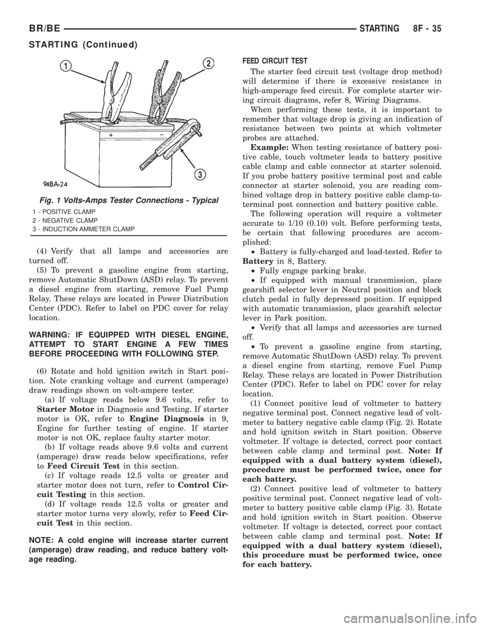
(1) Connect volt-ampere tester to battery terminals
(Fig. 1). See instructions provided by manufacturer of
volt-ampere tester being used.Note: If equipped
with dual battery system (diesel), tester should
be connected to driver side battery only. Also,
tester current reading must be taken from bat-
tery positive cable lead that connects to starter
motor.
(2) Fully engage parking brake.
(3) If equipped with manual transmission, place
gearshift selector lever in Neutral position and block
clutch pedal in fully depressed position. If equipped
with automatic transmission, place gearshift selector
lever in Park position.
8F - 34 STARTINGBR/BE
STARTING (Continued)
Page 506 of 2889
(4) Verify that all lamps and accessories are
turned off.
(5) To prevent a gasoline engine from starting,
remove Automatic ShutDown (ASD) relay. To prevent
a diesel engine from starting, remove Fuel Pump
Relay. These relays are located in Power Distribution
Center (PDC). Refer to label on PDC cover for relay
location.
WARNING: IF EQUIPPED WITH DIESEL ENGINE,
ATTEMPT TO START ENGINE A FEW TIMES
BEFORE PROCEEDING WITH FOLLOWING STEP.
(6) Rotate and hold ignition switch in Start posi-
tion. Note cranking voltage and current (amperage)
draw readings shown on volt-ampere tester.
(a) If voltage reads below 9.6 volts, refer to
Starter Motorin Diagnosis and Testing. If starter
motor is OK, refer toEngine Diagnosisin 9,
Engine for further testing of engine. If starter
motor is not OK, replace faulty starter motor.
(b) If voltage reads above 9.6 volts and current
(amperage) draw reads below specifications, refer
toFeed Circuit Testin this section.
(c) If voltage reads 12.5 volts or greater and
starter motor does not turn, refer toControl Cir-
cuit Testingin this section.
(d) If voltage reads 12.5 volts or greater and
starter motor turns very slowly, refer toFeed Cir-
cuit Testin this section.
NOTE: A cold engine will increase starter current
(amperage) draw reading, and reduce battery volt-
age reading.FEED CIRCUIT TEST
The starter feed circuit test (voltage drop method)
will determine if there is excessive resistance in
high-amperage feed circuit. For complete starter wir-
ing circuit diagrams, refer 8, Wiring Diagrams.
When performing these tests, it is important to
remember that voltage drop is giving an indication of
resistance between two points at which voltmeter
probes are attached.
Example:When testing resistance of battery posi-
tive cable, touch voltmeter leads to battery positive
cable clamp and cable connector at starter solenoid.
If you probe battery positive terminal post and cable
connector at starter solenoid, you are reading com-
bined voltage drop in battery positive cable clamp-to-
terminal post connection and battery positive cable.
The following operation will require a voltmeter
accurate to 1/10 (0.10) volt. Before performing tests,
be certain that following procedures are accom-
plished:
²Battery is fully-charged and load-tested. Refer to
Batteryin 8, Battery.
²Fully engage parking brake.
²If equipped with manual transmission, place
gearshift selector lever in Neutral position and block
clutch pedal in fully depressed position. If equipped
with automatic transmission, place gearshift selector
lever in Park position.
²Verify that all lamps and accessories are turned
off.
²To prevent a gasoline engine from starting,
remove Automatic ShutDown (ASD) relay. To prevent
a diesel engine from starting, remove Fuel Pump
Relay. These relays are located in Power Distribution
Center (PDC). Refer to label on PDC cover for relay
location.
(1) Connect positive lead of voltmeter to battery
negative terminal post. Connect negative lead of volt-
meter to battery negative cable clamp (Fig. 2). Rotate
and hold ignition switch in Start position. Observe
voltmeter. If voltage is detected, correct poor contact
between cable clamp and terminal post.Note: If
equipped with a dual battery system (diesel),
procedure must be performed twice, once for
each battery.
(2) Connect positive lead of voltmeter to battery
positive terminal post. Connect negative lead of volt-
meter to battery positive cable clamp (Fig. 3). Rotate
and hold ignition switch in Start position. Observe
voltmeter. If voltage is detected, correct poor contact
between cable clamp and terminal post.Note: If
equipped with a dual battery system (diesel),
this procedure must be performed twice, once
for each battery.
Fig. 1 Volts-Amps Tester Connections - Typical
1 - POSITIVE CLAMP
2 - NEGATIVE CLAMP
3 - INDUCTION AMMETER CLAMP
BR/BESTARTING 8F - 35
STARTING (Continued)