2001 DODGE RAM brake
[x] Cancel search: brakePage 311 of 2889
CABLE TENSIONER
ADJUSTMENT
NOTE: Tensioner adjustment is only necessary
when the tensioner, or a cable has been replaced or
disconnected for service. When adjustment is nec-
essary, perform adjustment only as described in the
following procedure. This is necessary to avoid
faulty park brake operation.
(1) Raise the vehicle.
(2) Back off the cable tensioner adjusting nut to
create slack in the cables.
(3) Remove the rear wheel/tire assemblies. Then
remove the brake drums.
(4) Verify the brakes are in good condition and
operating properly.
(5) Verify the park brake cables operate freely and
are not binding, or seized.
(6) Check the rear brake shoe adjustment with
standard brake gauge.
(7) Install the drums and verify that the drums
rotate freely without drag.
(8) Install the wheel/tire assemblies, (Refer to 22 -
TIRES/WHEELS/WHEELS - STANDARD PROCE-
DURE).
(9) Lower the vehicle enough for access to the park
brake foot pedal. Then fully apply the park brakes.
NOTE: Leave park brakes applied until adjustment
is complete.
(10) Raise the vehicle again.
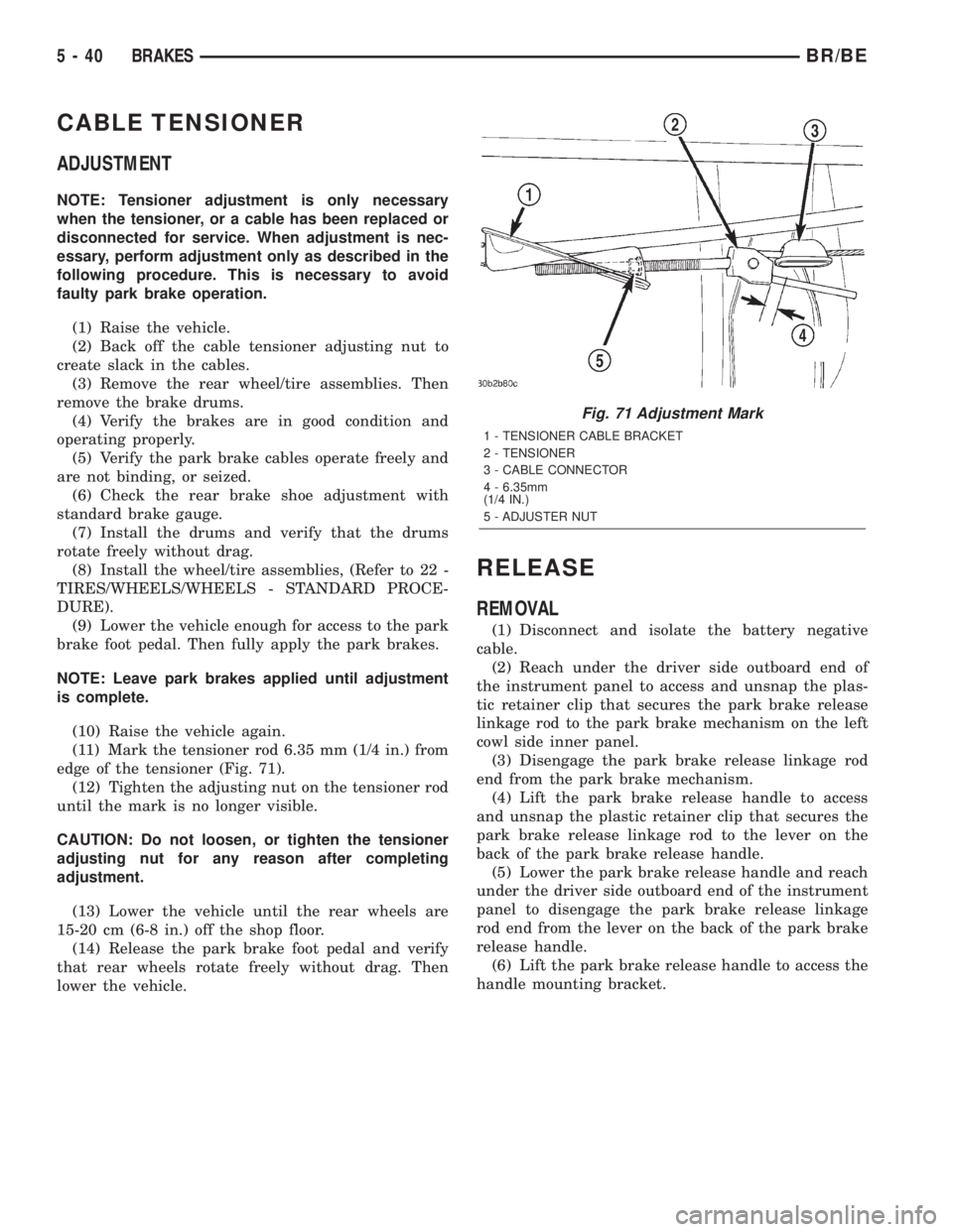
(11) Mark the tensioner rod 6.35 mm (1/4 in.) from
edge of the tensioner (Fig. 71).
(12) Tighten the adjusting nut on the tensioner rod
until the mark is no longer visible.
CAUTION: Do not loosen, or tighten the tensioner
adjusting nut for any reason after completing
adjustment.
(13) Lower the vehicle until the rear wheels are
15-20 cm (6-8 in.) off the shop floor.
(14) Release the park brake foot pedal and verify
that rear wheels rotate freely without drag. Then
lower the vehicle.
RELEASE
REMOVAL
(1) Disconnect and isolate the battery negative
cable.
(2) Reach under the driver side outboard end of
the instrument panel to access and unsnap the plas-
tic retainer clip that secures the park brake release
linkage rod to the park brake mechanism on the left
cowl side inner panel.
(3) Disengage the park brake release linkage rod
end from the park brake mechanism.
(4) Lift the park brake release handle to access
and unsnap the plastic retainer clip that secures the
park brake release linkage rod to the lever on the
back of the park brake release handle.
(5) Lower the park brake release handle and reach
under the driver side outboard end of the instrument
panel to disengage the park brake release linkage
rod end from the lever on the back of the park brake
release handle.
(6) Lift the park brake release handle to access the
handle mounting bracket.
Fig. 71 Adjustment Mark
1 - TENSIONER CABLE BRACKET
2 - TENSIONER
3 - CABLE CONNECTOR
4 - 6.35mm
(1/4 IN.)
5 - ADJUSTER NUT
5 - 40 BRAKESBR/BE
Page 312 of 2889
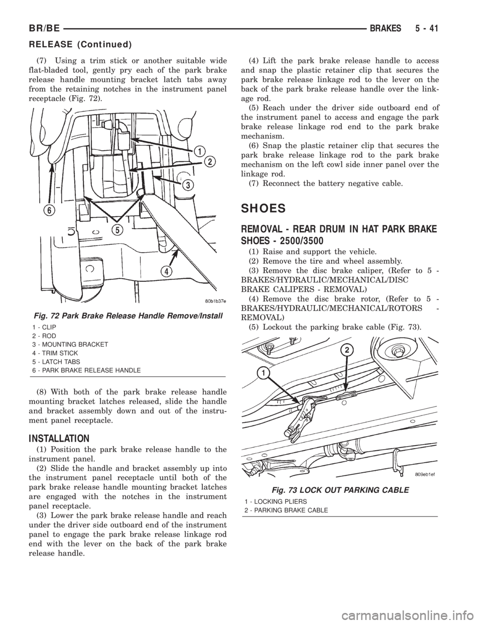
(7) Using a trim stick or another suitable wide
flat-bladed tool, gently pry each of the park brake
release handle mounting bracket latch tabs away
from the retaining notches in the instrument panel
receptacle (Fig. 72).
(8) With both of the park brake release handle
mounting bracket latches released, slide the handle
and bracket assembly down and out of the instru-
ment panel receptacle.
INSTALLATION
(1) Position the park brake release handle to the
instrument panel.
(2) Slide the handle and bracket assembly up into
the instrument panel receptacle until both of the
park brake release handle mounting bracket latches
are engaged with the notches in the instrument
panel receptacle.
(3) Lower the park brake release handle and reach
under the driver side outboard end of the instrument
panel to engage the park brake release linkage rod
end with the lever on the back of the park brake
release handle.(4) Lift the park brake release handle to access
and snap the plastic retainer clip that secures the
park brake release linkage rod to the lever on the
back of the park brake release handle over the link-
age rod.
(5) Reach under the driver side outboard end of
the instrument panel to access and engage the park
brake release linkage rod end to the park brake
mechanism.
(6) Snap the plastic retainer clip that secures the
park brake release linkage rod to the park brake
mechanism on the left cowl side inner panel over the
linkage rod.
(7) Reconnect the battery negative cable.
SHOES
REMOVAL - REAR DRUM IN HAT PARK BRAKE
SHOES - 2500/3500
(1) Raise and support the vehicle.
(2) Remove the tire and wheel assembly.
(3) Remove the disc brake caliper, (Refer to 5 -
BRAKES/HYDRAULIC/MECHANICAL/DISC
BRAKE CALIPERS - REMOVAL)
(4) Remove the disc brake rotor, (Refer to 5 -
BRAKES/HYDRAULIC/MECHANICAL/ROTORS -
REMOVAL)
(5) Lockout the parking brake cable (Fig. 73).
Fig. 72 Park Brake Release Handle Remove/Install
1 - CLIP
2 - ROD
3 - MOUNTING BRACKET
4 - TRIM STICK
5 - LATCH TABS
6 - PARK BRAKE RELEASE HANDLE
Fig. 73 LOCK OUT PARKING CABLE
1 - LOCKING PLIERS
2 - PARKING BRAKE CABLE
BR/BEBRAKES 5 - 41
RELEASE (Continued)
Page 313 of 2889
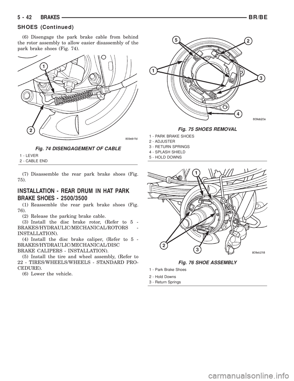
(6) Disengage the park brake cable from behind
the rotor assembly to allow easier disassembly of the
park brake shoes (Fig. 74).
(7) Disassemble the rear park brake shoes (Fig.
75).
INSTALLATION - REAR DRUM IN HAT PARK
BRAKE SHOES - 2500/3500
(1) Reassemble the rear park brake shoes (Fig.
76).
(2) Release the parking brake cable.
(3) Install the disc brake rotor, (Refer to 5 -
BRAKES/HYDRAULIC/MECHANICAL/ROTORS -
INSTALLATION).
(4) Install the disc brake caliper, (Refer to 5 -
BRAKES/HYDRAULIC/MECHANICAL/DISC
BRAKE CALIPERS - INSTALLATION).
(5) Install the tire and wheel assembly, (Refer to
22 - TIRES/WHEELS/WHEELS - STANDARD PRO-
CEDURE).
(6) Lower the vehicle.
Fig. 74 DISENGAGEMENT OF CABLE
1 - LEVER
2 - CABLE END
Fig. 75 SHOES REMOVAL
1 - PARK BRAKE SHOES
2 - ADJUSTER
3 - RETURN SPRINGS
4 - SPLASH SHIELD
5 - HOLD DOWNS
Fig. 76 SHOE ASSEMBLY
1 - Park Brake Shoes
2 - Hold Downs
3 - Return Springs
5 - 42 BRAKESBR/BE
SHOES (Continued)
Page 331 of 2889
OPERATION
The pilot bearing supports the transmission input
shaft, maintains proper clutch assembly alignment
and allows the transmission input shaft to rotate at a
different speed (RPM) than the engine mounted
crankshaft.
When the clutch pedal is depressed (with vehicle in
drive mode) the clutch disc slows and stops therefore,
the transmission input shaft slows and stops as well.
The pilot bearing allows the engine crankshaft to
continue to rotate even though the transmission
input shaft is stationary.
REMOVAL
(1) Remove transmission, transfer case, if
equipped, and clutch housing. Refer to Group 21,
Transmission and Transfer Case, for proper proce-
dures.
(2) Remove clutch cover and disc.
(3) Using a suitable blind hole puller, remove pilot
bearing.
INSTALLATION
(1) Clean bearing bore with solvent and wipe dry
with shop towel.
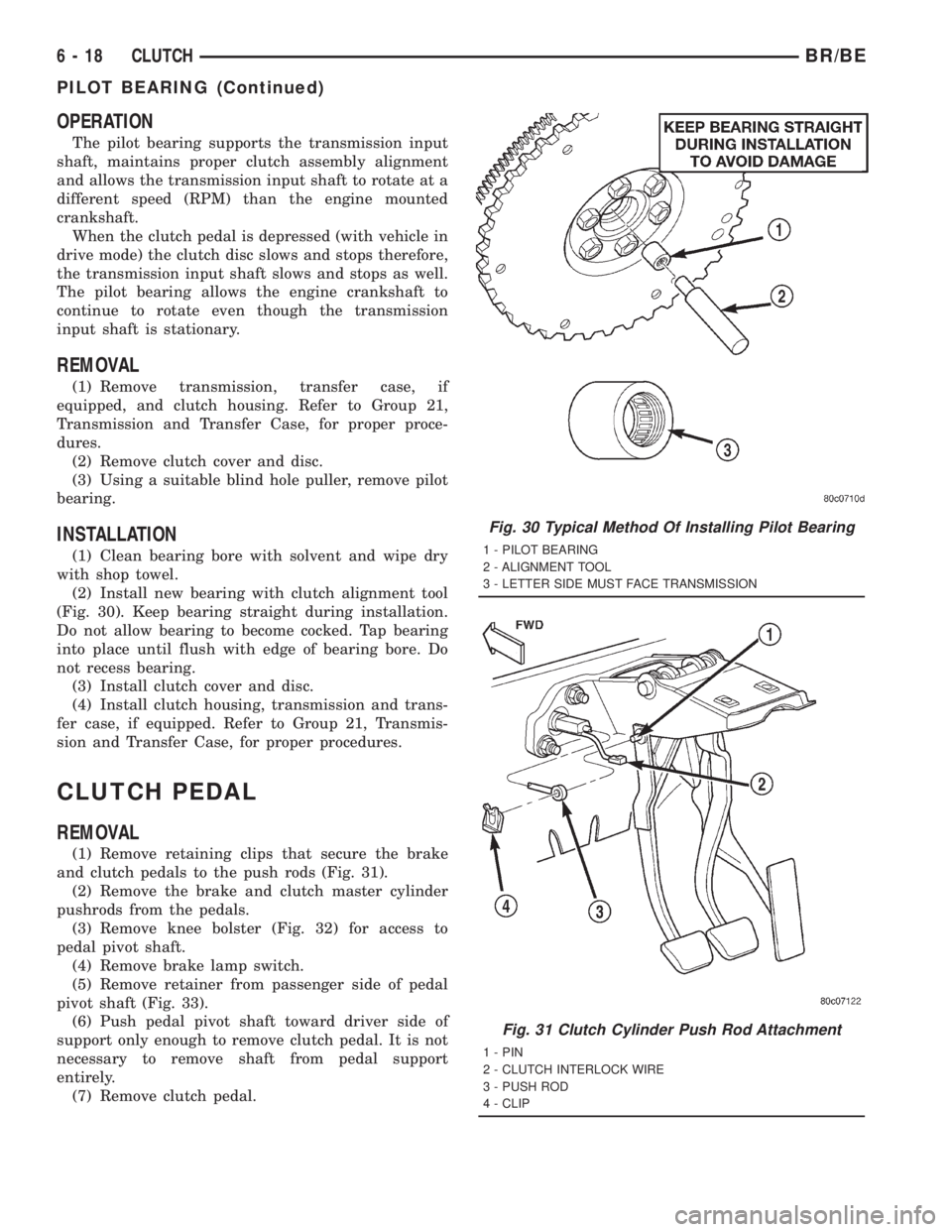
(2) Install new bearing with clutch alignment tool
(Fig. 30). Keep bearing straight during installation.
Do not allow bearing to become cocked. Tap bearing
into place until flush with edge of bearing bore. Do
not recess bearing.
(3) Install clutch cover and disc.
(4) Install clutch housing, transmission and trans-
fer case, if equipped. Refer to Group 21, Transmis-
sion and Transfer Case, for proper procedures.
CLUTCH PEDAL
REMOVAL
(1) Remove retaining clips that secure the brake
and clutch pedals to the push rods (Fig. 31).
(2) Remove the brake and clutch master cylinder
pushrods from the pedals.
(3) Remove knee bolster (Fig. 32) for access to
pedal pivot shaft.
(4) Remove brake lamp switch.
(5) Remove retainer from passenger side of pedal
pivot shaft (Fig. 33).
(6) Push pedal pivot shaft toward driver side of
support only enough to remove clutch pedal. It is not
necessary to remove shaft from pedal support
entirely.
(7) Remove clutch pedal.
Fig. 30 Typical Method Of Installing Pilot Bearing
1 - PILOT BEARING
2 - ALIGNMENT TOOL
3 - LETTER SIDE MUST FACE TRANSMISSION
Fig. 31 Clutch Cylinder Push Rod Attachment
1 - PIN
2 - CLUTCH INTERLOCK WIRE
3 - PUSH ROD
4 - CLIP
6 - 18 CLUTCHBR/BE
PILOT BEARING (Continued)
Page 332 of 2889
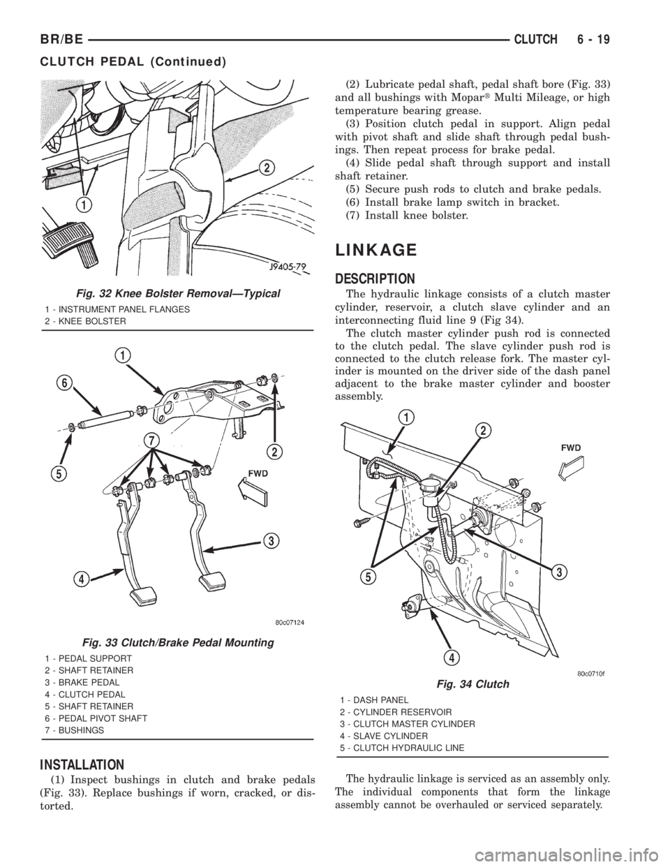
INSTALLATION
(1) Inspect bushings in clutch and brake pedals
(Fig. 33). Replace bushings if worn, cracked, or dis-
torted.(2) Lubricate pedal shaft, pedal shaft bore (Fig. 33)
and all bushings with MopartMulti Mileage, or high
temperature bearing grease.
(3) Position clutch pedal in support. Align pedal
with pivot shaft and slide shaft through pedal bush-
ings. Then repeat process for brake pedal.
(4) Slide pedal shaft through support and install
shaft retainer.
(5) Secure push rods to clutch and brake pedals.
(6) Install brake lamp switch in bracket.
(7) Install knee bolster.
LINKAGE
DESCRIPTION
The hydraulic linkage consists of a clutch master
cylinder, reservoir, a clutch slave cylinder and an
interconnecting fluid line 9 (Fig 34).
The clutch master cylinder push rod is connected
to the clutch pedal. The slave cylinder push rod is
connected to the clutch release fork. The master cyl-
inder is mounted on the driver side of the dash panel
adjacent to the brake master cylinder and booster
assembly.
The hydraulic linkage is serviced as an assembly only.
The individual components that form the linkage
assembly cannot be overhauled or serviced separately.
Fig. 32 Knee Bolster RemovalÐTypical
1 - INSTRUMENT PANEL FLANGES
2 - KNEE BOLSTER
Fig. 33 Clutch/Brake Pedal Mounting
1 - PEDAL SUPPORT
2 - SHAFT RETAINER
3 - BRAKE PEDAL
4 - CLUTCH PEDAL
5 - SHAFT RETAINER
6 - PEDAL PIVOT SHAFT
7 - BUSHINGS
Fig. 34 Clutch
1 - DASH PANEL
2 - CYLINDER RESERVOIR
3 - CLUTCH MASTER CYLINDER
4 - SLAVE CYLINDER
5 - CLUTCH HYDRAULIC LINE
BR/BECLUTCH 6 - 19
CLUTCH PEDAL (Continued)
Page 339 of 2889
OPERATIONÐCOOLING SYSTEM
The cooling system regulates engine operating tem-
perature. It allows the engine to reach normal oper-
ating temperature as quickly as possible. It also
maintains normal operating temperature and pre-
vents overheating.
The cooling system also provides a means of heat-
ing the passenger compartment and cooling the auto-
matic transmission fluid (if equipped). The cooling
system is pressurized and uses a centrifugal water
pump to circulate coolant throughout the system.
An optional factory installed maximum duty cool-
ing package is available on most models. This pack-
age will provide additional cooling capacity for
vehicles used under extreme conditions such as
trailer towing in high ambient temperatures.
DIAGNOSIS AND TESTING - PRELIMINARY
CHECKS
ENGINE COOLING SYSTEM OVERHEATING
Establish what driving conditions caused the com-
plaint. Abnormal loads on the cooling system such as
the following may be the cause:
²PROLONGED IDLE
²VERY HIGH AMBIENT TEMPERATURE
²SLIGHT TAIL WIND AT IDLE
²SLOW TRAFFIC
²TRAFFIC JAMS
²HIGH SPEED OR STEEP GRADES
Driving techniques that avoid overheating are:
²Idle with A/C off when temperature gauge is at
end of normal range.²Increasing engine speed for more air flow is rec-
ommended.
TRAILER TOWING:
Consult Trailer Towing section of owners manual.
Do not exceed limits.
AIR CONDITIONING; ADD-ON OR AFTER MARKET:
A maximum cooling package should have been
ordered with vehicle if add-on or after market A/C is
installed. If not, maximum cooling system compo-
nents should be installed for model involved per
manufacturer's specifications.
RECENT SERVICE OR ACCIDENT REPAIR:
Determine if any recent service has been per-
formed on vehicle that may effect cooling system.
This may be:
²Engine adjustments (incorrect timing)
²Slipping engine accessory drive belt(s)
²Brakes (possibly dragging)
²Changed parts. Incorrect water pump or pump
rotating in wrong direction due to belt not correctly
routed
²Reconditioned radiator or cooling system refill-
ing (possibly under filled or air trapped in system).
NOTE: If investigation reveals none of the previous
items as a cause for an engine overheating com-
plaint, (Refer to 7 - COOLING - DIAGNOSIS AND
TESTING)
DIAGNOSIS AND TESTINGÐON-BOARD
DIAGNOSTICS (OBD)
COOLING SYSTEM RELATED DIAGNOSTICS
The powertrain control module (PCM) has been
programmed to monitor certain cooling system com-
ponents:
²If the engine has remained cool for too long a
period, such as with a stuck open thermostat, a Diag-
nostic Trouble Code (DTC) can be set.
²If an open or shorted condition has developed in
the relay circuit controlling the electric radiator fan,
a Diagnostic Trouble Code (DTC) can be set.
If the problem is sensed in a monitored circuit
often enough to indicated an actual problem, a DTC
is stored. The DTC will be stored in the PCM mem-
ory for eventual display to the service technician.
(Refer to 25 - EMISSIONS CONTROL - DESCRIP-
TION).
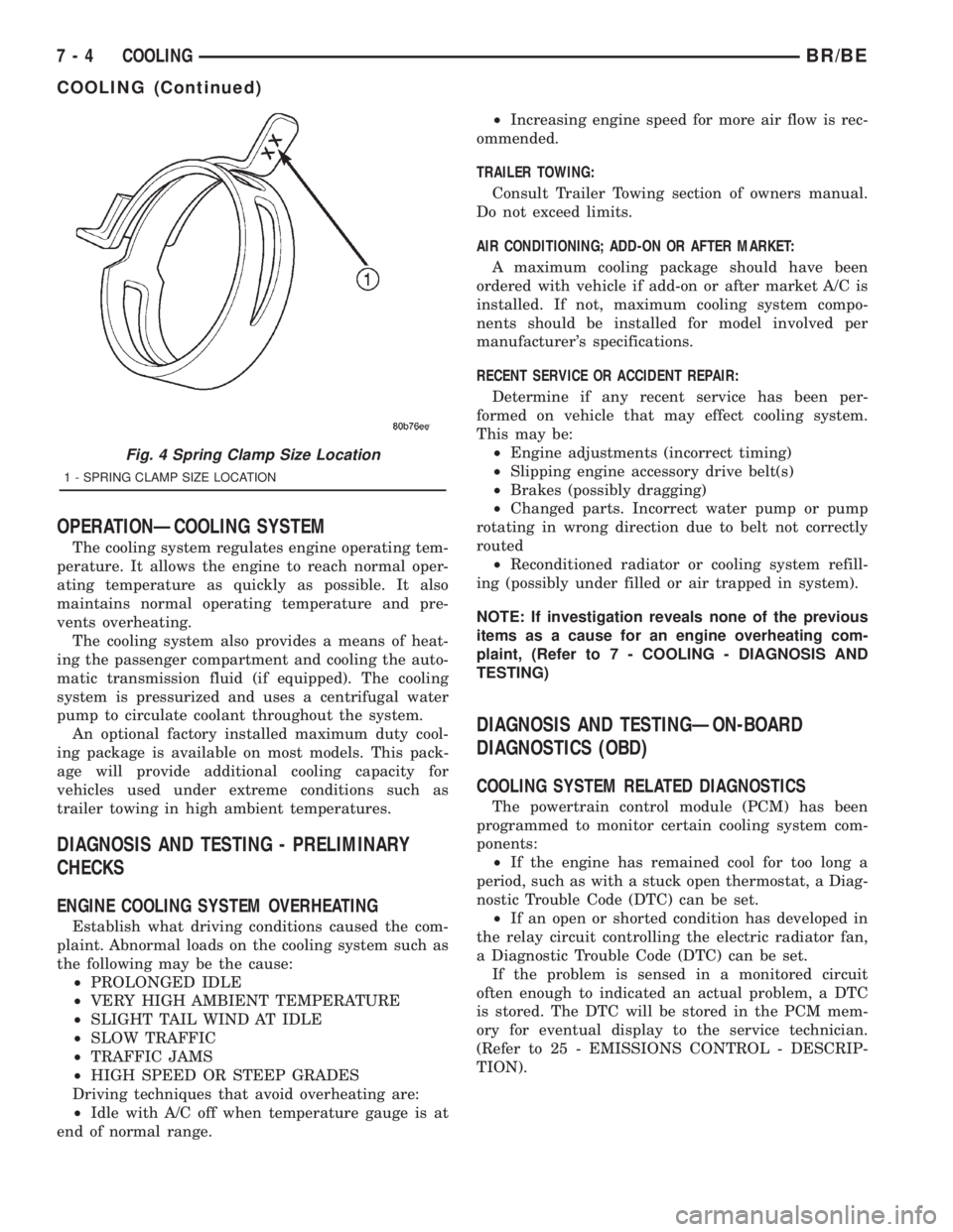
Fig. 4 Spring Clamp Size Location
1 - SPRING CLAMP SIZE LOCATION
7 - 4 COOLINGBR/BE
COOLING (Continued)
Page 343 of 2889
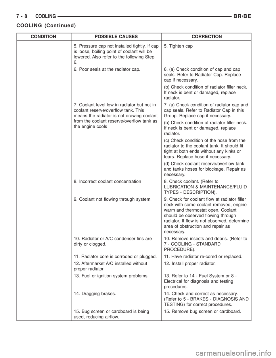
CONDITION POSSIBLE CAUSES CORRECTION
5. Pressure cap not installed tightly. If cap
is loose, boiling point of coolant will be
lowered. Also refer to the following Step
6.5. Tighten cap
6. Poor seals at the radiator cap. 6. (a) Check condition of cap and cap
seals. Refer to Radiator Cap. Replace
cap if necessary.
(b) Check condition of radiator filler neck.
If neck is bent or damaged, replace
radiator.
7. Coolant level low in radiator but not in
coolant reserve/overflow tank. This
means the radiator is not drawing coolant
from the coolant reserve/overflow tank as
the engine cools7. (a) Check condition of radiator cap and
cap seals. Refer to Radiator Cap in this
Group. Replace cap if necessary.
(b) Check condition of radiator filler neck.
If neck is bent or damaged, replace
radiator.
(c) Check condition of the hose from the
radiator to the coolant tank. It should fit
tight at both ends without any kinks or
tears. Replace hose if necessary.
(d) Check coolant reserve/overflow tank
and tanks hoses for blockage. Repair as
necessary.
8. Incorrect coolant concentration 8. Check coolant. (Refer to
LUBRICATION & MAINTENANCE/FLUID
TYPES - DESCRIPTION).
9. Coolant not flowing through system 9. Check for coolant flow at radiator filler
neck with some coolant removed, engine
warm and thermostat open. Coolant
should be observed flowing through
radiator. If flow is not observed, determine
area of obstruction and repair as
necessary.
10. Radiator or A/C condenser fins are
dirty or clogged.10. Remove insects and debris. (Refer to
7 - COOLING - STANDARD
PROCEDURE).
11. Radiator core is corroded or plugged. 11. Have radiator re-cored or replaced.
12. Aftermarket A/C installed without
proper radiator.12. Install proper radiator.
13. Fuel or ignition system problems. 13. Refer to 14 - Fuel System or 8 -
Electrical for diagnosis and testing
procedures.
14. Dragging brakes. 14. Check and correct as necessary.
(Refer to 5 - BRAKES - DIAGNOSIS AND
TESTING) for correct procedures.
15. Bug screen or cardboard is being
used, reducing airflow.15. Remove bug screen or cardboard.
7 - 8 COOLINGBR/BE
COOLING (Continued)
Page 348 of 2889

CONDITION POSSIBLE CAUSES CORRECTION
6. Coolant mixture incorrect. 6. Drain cooling system (Refer to 7 -
COOLING - STANDARD
PROCEDURE) refill with correct
mixture (Refer to 7 - COOLING -
STANDARD PROCEDURE).
7. Thermostat stuck shut. 7. Replace thermostat.
8. Bug screen or winter front being
used.8. Remove bug screen or winter
front.
9. Viscous fan drive not operating
properly.9. Check viscous fan (Refer to 7 -
COOLING/ENGINE/FAN DRIVE
VISCOUS CLUTCH - DIAGNOSIS
AND TESTING)
10. Cylinder head gasket leaking. 10. Check for leaking head gaskets
(Refer to 7 - COOLING -
DIAGNOSIS AND TESTING).
11. Heater core leaking. 11. Replace heater core.
12. cooling system hoses leaking. 12. Tighten clamps or Replace
hoses.
13. Brakes dragging. 13. Check brakes. (Refer to 5 -
BRAKES/HYDRAULIC/
MECHANICAL - DIAGNOSIS AND
TESTING)
TEMPERATURE GAUGE READING
INCONSISTENT ( ERRATIC,
CYCLES OR FLUCTUATES)1. Heavy duty cooling system,
extream cold ambient (outside)
temperature or heater blower motor
in high position.1. None. System operating normaly.
2. Temperature gauge or gauge
sensor defective.2. Check gauge. (Refer to 8 -
ELECTRICAL/INSTRUMENT
CLUSTER - DIAGNOSIS AND
TESTING)
3. Temporary heavy usage or load. 3. None. Normal condition.
4. Air traped in cooling system. 4. Fill cooling system (Refer to 7 -
COOLING - STANDARD
PROCEDURE).
5. Water pump 5. Replace water pump.
6. Air leak on suction side of water
pump.6. Check for leak. (Refer to 7 -
COOLING - DIAGNOSIS AND
TESTING)
RADIATOR CAP LEAKING STEAM
AND /OR COOLANT INTO
RESERVOIR BOTTLE.
(TEMPERATURE GAUGE MAY
READ HIGH)1. Radiator cap defective. 1. Replace radiator cap.
2. Radiator neck surface damaged. 2. Replace radiator.
BR/BECOOLING 7 - 13
COOLING (Continued)