2001 DODGE RAM brake
[x] Cancel search: brakePage 295 of 2889
REMOVAL - FRONT
(1) Raise and support vehicle.
(2) Remove front wheel and tire assemblies.
(3) Compress caliper.
(4) Remove caliper, (Refer to 5 - BRAKES/HY-
DRAULIC/MECHANICAL/DISC BRAKE CALIPERS
- REMOVAL).
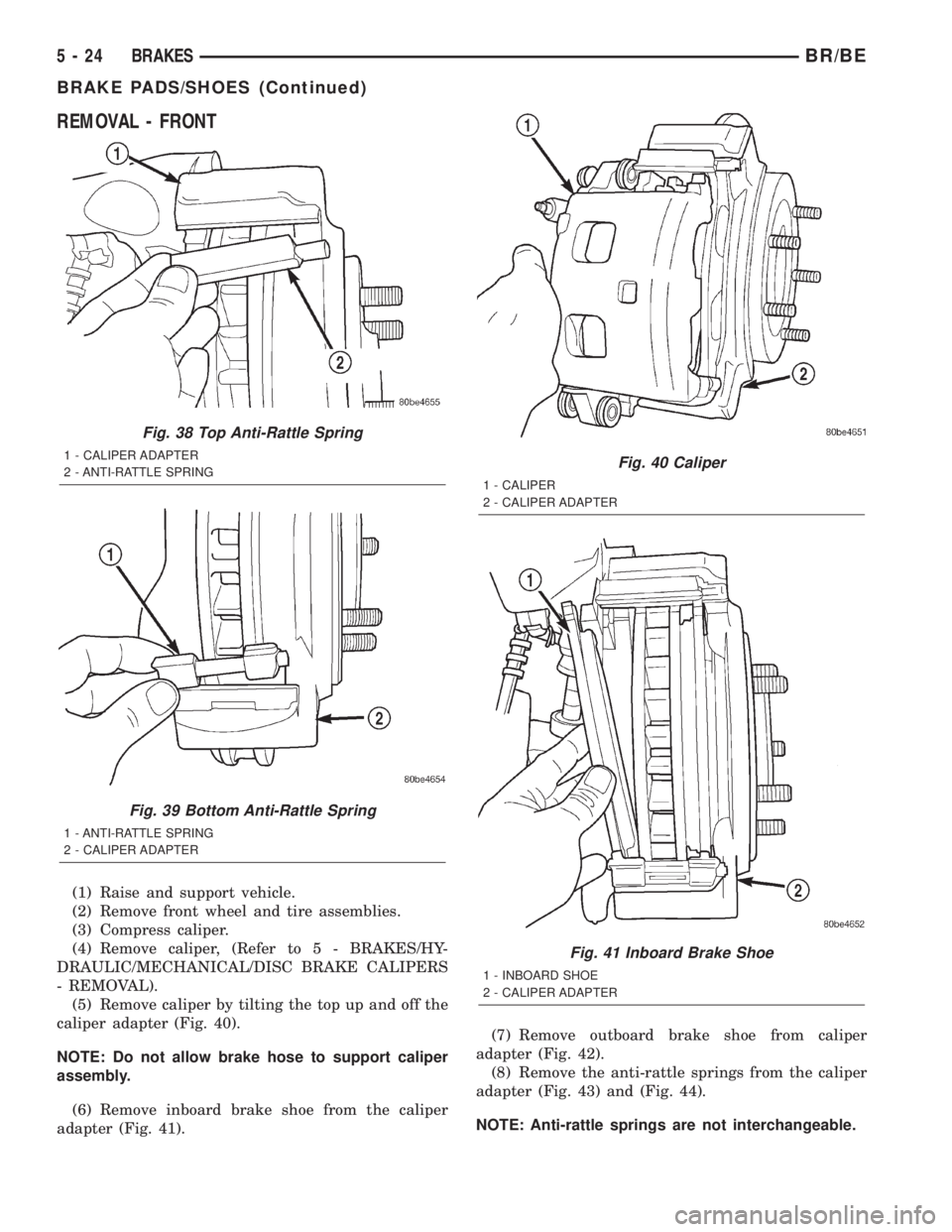
(5) Remove caliper by tilting the top up and off the
caliper adapter (Fig. 40).
NOTE: Do not allow brake hose to support caliper
assembly.
(6) Remove inboard brake shoe from the caliper
adapter (Fig. 41).(7) Remove outboard brake shoe from caliper
adapter (Fig. 42).
(8) Remove the anti-rattle springs from the caliper
adapter (Fig. 43) and (Fig. 44).
NOTE: Anti-rattle springs are not interchangeable.
Fig. 38 Top Anti-Rattle Spring
1 - CALIPER ADAPTER
2 - ANTI-RATTLE SPRING
Fig. 39 Bottom Anti-Rattle Spring
1 - ANTI-RATTLE SPRING
2 - CALIPER ADAPTER
Fig. 40 Caliper
1 - CALIPER
2 - CALIPER ADAPTER
Fig. 41 Inboard Brake Shoe
1 - INBOARD SHOE
2 - CALIPER ADAPTER
5 - 24 BRAKESBR/BE
BRAKE PADS/SHOES (Continued)
Page 296 of 2889
REMOVAL - REAR BRAKE SHOES-11 inch
(1) Raise and support vehicle.
(2) Remove wheel and tire assembly.
(3) Remove clip nuts securing brake drum to wheel
studs.
(4) Remove drum. If drum is difficult to remove,
remove rear plug from access hole in support plate.
Back-off self adjusting by inserting a thin screw-
driver into access hole and push lever away from
adjuster screw star wheel. Then insert an adjustertool into brake adjusting hole rotate adjuster star
wheel to retract brake shoes.
(5) Vacuum brake components to remove brake lin-
ing dust.
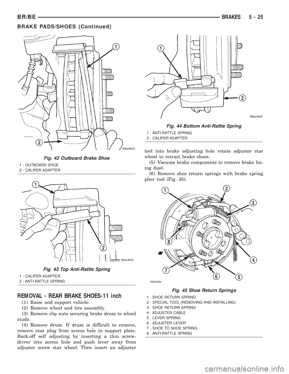
(6) Remove shoe return springs with brake spring
plier tool (Fig. 45).
Fig. 42 Outboard Brake Shoe
1 - OUTBOARD SHOE
2 - CALIPER ADAPTER
Fig. 43 Top Anti-Rattle Spring
1 - CALIPER ADAPTER
2 - ANTI-RATTLE SPRING
Fig. 44 Bottom Anti-Rattle Spring
1 - ANTI-RATTLE SPRING
2 - CALIPER ADAPTER
Fig. 45 Shoe Return Springs
1 - SHOE RETURN SPRING
2 - SPECIAL TOOL (REMOVING AND INSTALLING)
3 - SHOE RETURN SPRING
4 - ADJUSTER CABLE
5 - LEVER SPRING
6 - ADJUSTER LEVER
7 - SHOE TO SHOE SPRING
8 - ANTI-RATTLE SPRING
BR/BEBRAKES 5 - 25
BRAKE PADS/SHOES (Continued)
Page 297 of 2889
(7) Remove adjuster cable. Slide cable eye off
anchor pin. Then unhook and remove cable from
adjuster lever.
(8) Remove cable guide from secondary shoe and
anchor plate from anchor pin.
(9) Remove adjuster lever. Disengage lever from
spring by sliding lever forward to clear pivot and
work lever out from under spring.
(10) Remove adjuster lever spring from pivot.
(11) Disengage and remove shoe to shoe spring
from brake shoes.
(12) Disengage and remove adjuster screw assem-
bly from brake shoes.
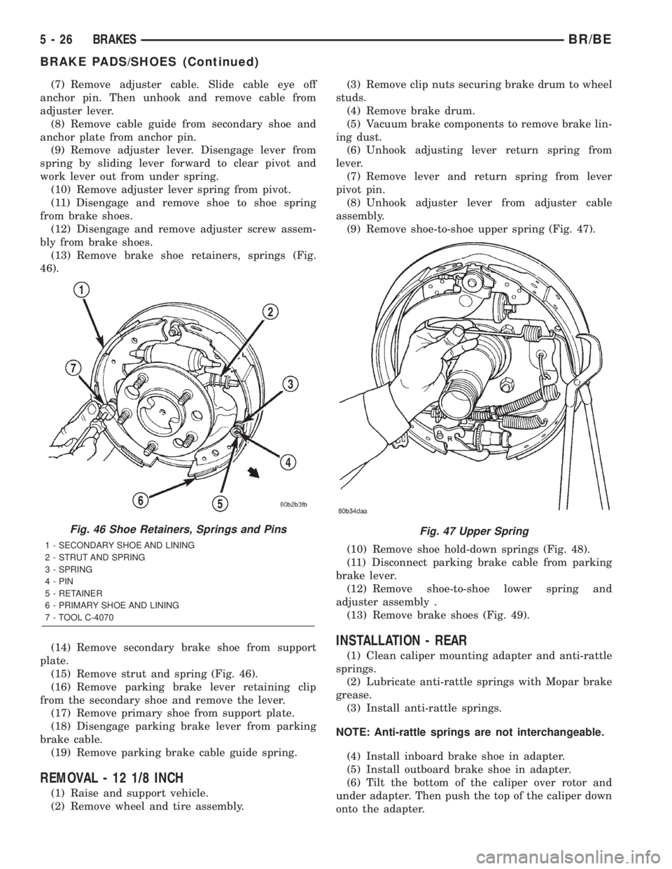
(13) Remove brake shoe retainers, springs (Fig.
46).
(14) Remove secondary brake shoe from support
plate.
(15) Remove strut and spring (Fig. 46).
(16) Remove parking brake lever retaining clip
from the secondary shoe and remove the lever.
(17) Remove primary shoe from support plate.
(18) Disengage parking brake lever from parking
brake cable.
(19) Remove parking brake cable guide spring.
REMOVAL - 12 1/8 INCH
(1) Raise and support vehicle.
(2) Remove wheel and tire assembly.(3) Remove clip nuts securing brake drum to wheel
studs.
(4) Remove brake drum.
(5) Vacuum brake components to remove brake lin-
ing dust.
(6) Unhook adjusting lever return spring from
lever.
(7) Remove lever and return spring from lever
pivot pin.
(8) Unhook adjuster lever from adjuster cable
assembly.
(9) Remove shoe-to-shoe upper spring (Fig. 47).
(10) Remove shoe hold-down springs (Fig. 48).
(11) Disconnect parking brake cable from parking
brake lever.
(12) Remove shoe-to-shoe lower spring and
adjuster assembly .
(13) Remove brake shoes (Fig. 49).
INSTALLATION - REAR
(1) Clean caliper mounting adapter and anti-rattle
springs.
(2) Lubricate anti-rattle springs with Mopar brake
grease.
(3) Install anti-rattle springs.
NOTE: Anti-rattle springs are not interchangeable.
(4) Install inboard brake shoe in adapter.
(5) Install outboard brake shoe in adapter.
(6) Tilt the bottom of the caliper over rotor and
under adapter. Then push the top of the caliper down
onto the adapter.
Fig. 46 Shoe Retainers, Springs and Pins
1 - SECONDARY SHOE AND LINING
2 - STRUT AND SPRING
3 - SPRING
4 - PIN
5 - RETAINER
6 - PRIMARY SHOE AND LINING
7 - TOOL C-4070
Fig. 47 Upper Spring
5 - 26 BRAKESBR/BE
BRAKE PADS/SHOES (Continued)
Page 298 of 2889
(7) Install caliper, (Refer to 5 - BRAKES/HY-
DRAULIC/MECHANICAL/DISC BRAKE CALIPERS
- INSTALLATION) (Refer to 5 - BRAKES/HYDRAU-
LIC/MECHANICAL/DISC BRAKE CALIPERS -
INSTALLATION).
(8) Install wheel and tire assemblies and lower
vehicle, (Refer to 22 - TIRES/WHEELS/WHEELS -
STANDARD PROCEDURE).
(9) Apply brakes several times to seat caliper pis-
tons and brake shoes and obtain firm pedal.(10) Top off master cylinder fluid level.
INSTALLATION - FRONT
(1) Bottom pistons in caliper bore with C-clamp.
Place an old brake shoe between a C-clamp and cal-
iper piston.
(2) Clean caliper mounting adapter and anti-rattle
springs.
(3) Lubricate anti-rattle springs with Mopar brake
grease.
(4) Install anti-rattle springs.
NOTE: Anti-rattle springs are not interchangeable.
(5) Install inboard brake shoe in adapter.
(6) Install outboard brake shoe in adapter.
(7) Tilt the bottom of the caliper over rotor and
under adapter. Then push the top of the caliper down
onto the adapter.
(8) Install caliper, (Refer to 5 - BRAKES/HY-
DRAULIC/MECHANICAL/DISC BRAKE CALIPERS
- INSTALLATION).
(9) Install wheel and tire assemblies and lower
vehicle, (Refer to 22 - TIRES/WHEELS/WHEELS -
STANDARD PROCEDURE).
(10) Apply brakes several times to seat caliper pis-
tons and brake shoes and obtain firm pedal.
(11) Top off master cylinder fluid level.
INSTALLATION - REAR BRAKE SHOES-11 inch
(1) Clean and inspect individual brake compo-
nents, (Refer to 5 - BRAKES/HYDRAULIC/ME-
CHANICAL/DRUM - CLEANING).
(2) Lubricate anchor pin and brake shoe contact
pads on support plate with high temperature grease
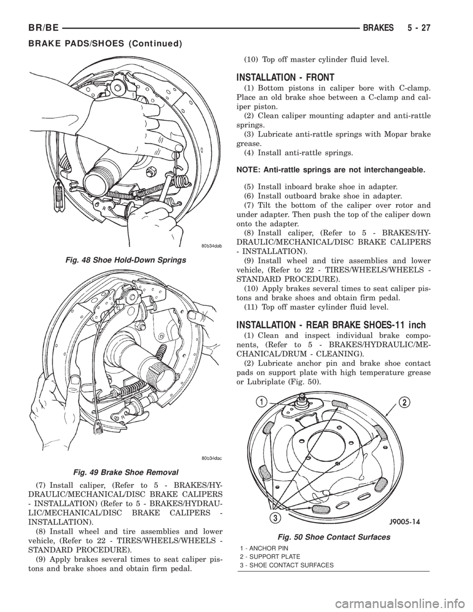
or Lubriplate (Fig. 50).
Fig. 48 Shoe Hold-Down Springs
Fig. 49 Brake Shoe Removal
Fig. 50 Shoe Contact Surfaces
1 - ANCHOR PIN
2 - SUPPORT PLATE
3 - SHOE CONTACT SURFACES
BR/BEBRAKES 5 - 27
BRAKE PADS/SHOES (Continued)
Page 299 of 2889
(3) Lubricate adjuster screw socket, nut, button
and screw thread surfaces with grease or Lubriplate.
(4) Install parking brake lever to the secondary
shoe and install retaining clip.
(5) Install primary shoe on support plate. Secure
shoe with new spring retainers and pin.
(6) Install spring on parking brake strut and
engage strut in primary.
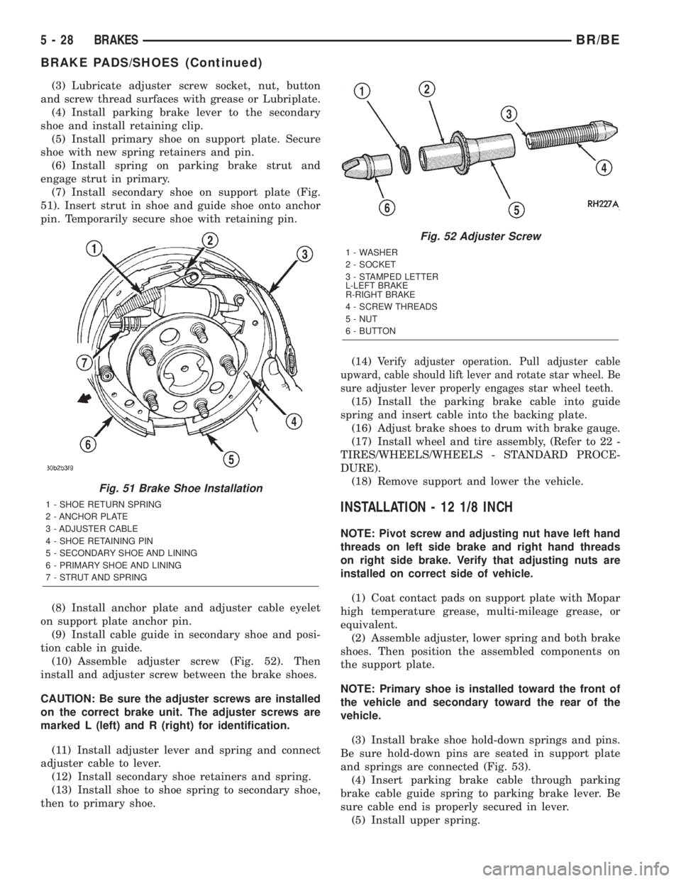
(7) Install secondary shoe on support plate (Fig.
51). Insert strut in shoe and guide shoe onto anchor
pin. Temporarily secure shoe with retaining pin.
(8) Install anchor plate and adjuster cable eyelet
on support plate anchor pin.
(9) Install cable guide in secondary shoe and posi-
tion cable in guide.
(10) Assemble adjuster screw (Fig. 52). Then
install and adjuster screw between the brake shoes.
CAUTION: Be sure the adjuster screws are installed
on the correct brake unit. The adjuster screws are
marked L (left) and R (right) for identification.
(11) Install adjuster lever and spring and connect
adjuster cable to lever.
(12) Install secondary shoe retainers and spring.
(13) Install shoe to shoe spring to secondary shoe,
then to primary shoe.(14)
Verify adjuster operation. Pull adjuster cable
upward, cable should lift lever and rotate star wheel. Be
sure adjuster lever properly engages star wheel teeth.
(15) Install the parking brake cable into guide
spring and insert cable into the backing plate.
(16) Adjust brake shoes to drum with brake gauge.
(17) Install wheel and tire assembly, (Refer to 22 -
TIRES/WHEELS/WHEELS - STANDARD PROCE-
DURE).
(18) Remove support and lower the vehicle.
INSTALLATION - 12 1/8 INCH
NOTE: Pivot screw and adjusting nut have left hand
threads on left side brake and right hand threads
on right side brake. Verify that adjusting nuts are
installed on correct side of vehicle.
(1) Coat contact pads on support plate with Mopar
high temperature grease, multi-mileage grease, or
equivalent.
(2) Assemble adjuster, lower spring and both brake
shoes. Then position the assembled components on
the support plate.
NOTE: Primary shoe is installed toward the front of
the vehicle and secondary toward the rear of the
vehicle.
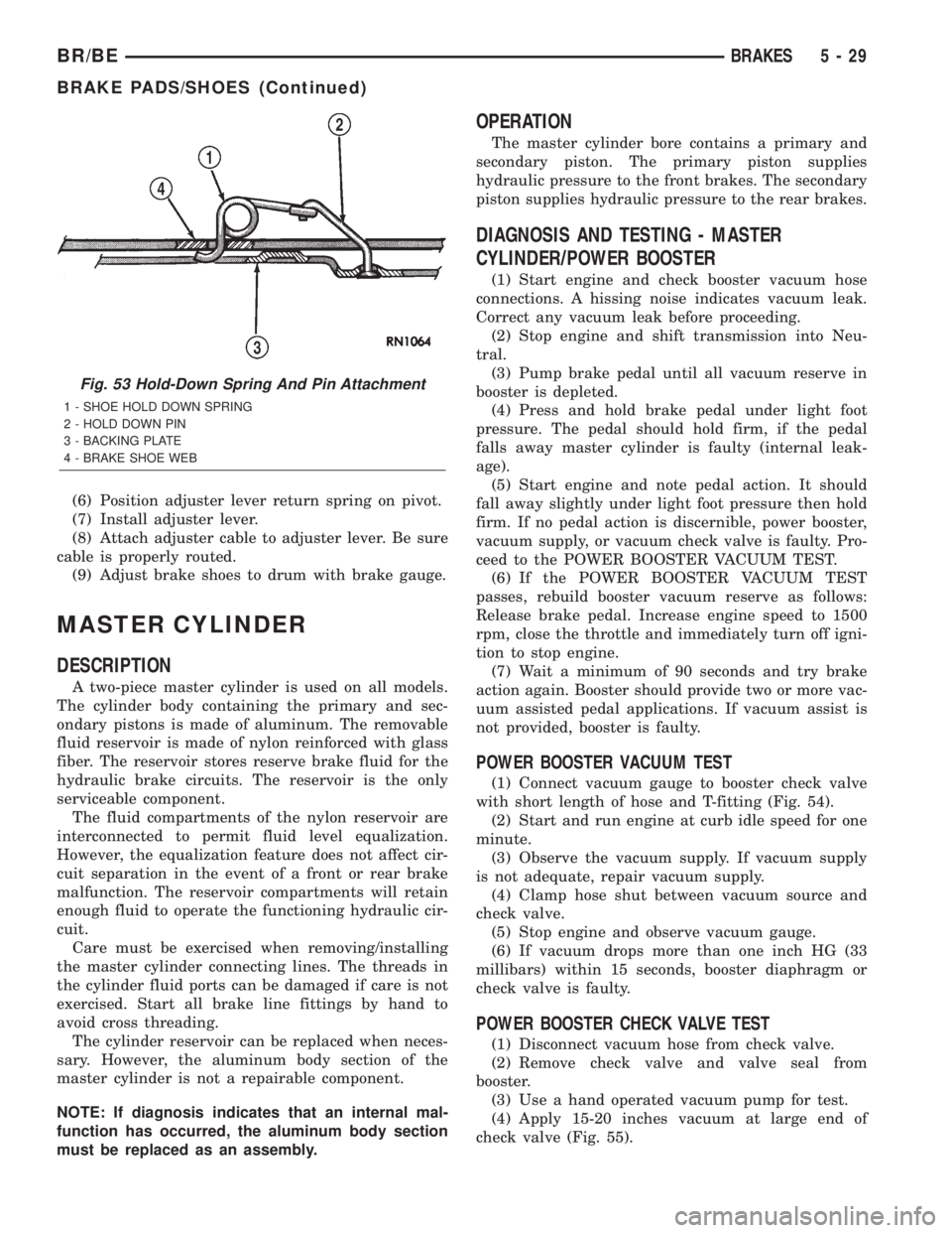
(3) Install brake shoe hold-down springs and pins.
Be sure hold-down pins are seated in support plate
and springs are connected (Fig. 53).
(4) Insert parking brake cable through parking
brake cable guide spring to parking brake lever. Be
sure cable end is properly secured in lever.
(5) Install upper spring.
Fig. 51 Brake Shoe Installation
1 - SHOE RETURN SPRING
2 - ANCHOR PLATE
3 - ADJUSTER CABLE
4 - SHOE RETAINING PIN
5 - SECONDARY SHOE AND LINING
6 - PRIMARY SHOE AND LINING
7 - STRUT AND SPRING
Fig. 52 Adjuster Screw
1 - WASHER
2 - SOCKET
3 - STAMPED LETTER
L-LEFT BRAKE
R-RIGHT BRAKE
4 - SCREW THREADS
5 - NUT
6 - BUTTON
5 - 28 BRAKESBR/BE
BRAKE PADS/SHOES (Continued)
Page 300 of 2889
(6) Position adjuster lever return spring on pivot.
(7) Install adjuster lever.
(8) Attach adjuster cable to adjuster lever. Be sure
cable is properly routed.
(9) Adjust brake shoes to drum with brake gauge.
MASTER CYLINDER
DESCRIPTION
A two-piece master cylinder is used on all models.
The cylinder body containing the primary and sec-
ondary pistons is made of aluminum. The removable
fluid reservoir is made of nylon reinforced with glass
fiber. The reservoir stores reserve brake fluid for the
hydraulic brake circuits. The reservoir is the only
serviceable component.
The fluid compartments of the nylon reservoir are
interconnected to permit fluid level equalization.
However, the equalization feature does not affect cir-
cuit separation in the event of a front or rear brake
malfunction. The reservoir compartments will retain
enough fluid to operate the functioning hydraulic cir-
cuit.
Care must be exercised when removing/installing
the master cylinder connecting lines. The threads in
the cylinder fluid ports can be damaged if care is not
exercised. Start all brake line fittings by hand to
avoid cross threading.
The cylinder reservoir can be replaced when neces-
sary. However, the aluminum body section of the
master cylinder is not a repairable component.
NOTE: If diagnosis indicates that an internal mal-
function has occurred, the aluminum body section
must be replaced as an assembly.
OPERATION
The master cylinder bore contains a primary and
secondary piston. The primary piston supplies
hydraulic pressure to the front brakes. The secondary
piston supplies hydraulic pressure to the rear brakes.
DIAGNOSIS AND TESTING - MASTER
CYLINDER/POWER BOOSTER
(1) Start engine and check booster vacuum hose
connections. A hissing noise indicates vacuum leak.
Correct any vacuum leak before proceeding.
(2) Stop engine and shift transmission into Neu-
tral.
(3) Pump brake pedal until all vacuum reserve in
booster is depleted.
(4) Press and hold brake pedal under light foot
pressure. The pedal should hold firm, if the pedal
falls away master cylinder is faulty (internal leak-
age).
(5) Start engine and note pedal action. It should
fall away slightly under light foot pressure then hold
firm. If no pedal action is discernible, power booster,
vacuum supply, or vacuum check valve is faulty. Pro-
ceed to the POWER BOOSTER VACUUM TEST.
(6) If the POWER BOOSTER VACUUM TEST
passes, rebuild booster vacuum reserve as follows:
Release brake pedal. Increase engine speed to 1500
rpm, close the throttle and immediately turn off igni-
tion to stop engine.
(7) Wait a minimum of 90 seconds and try brake
action again. Booster should provide two or more vac-
uum assisted pedal applications. If vacuum assist is
not provided, booster is faulty.
POWER BOOSTER VACUUM TEST
(1) Connect vacuum gauge to booster check valve
with short length of hose and T-fitting (Fig. 54).
(2) Start and run engine at curb idle speed for one
minute.
(3) Observe the vacuum supply. If vacuum supply
is not adequate, repair vacuum supply.
(4) Clamp hose shut between vacuum source and
check valve.
(5) Stop engine and observe vacuum gauge.
(6) If vacuum drops more than one inch HG (33
millibars) within 15 seconds, booster diaphragm or
check valve is faulty.
POWER BOOSTER CHECK VALVE TEST
(1) Disconnect vacuum hose from check valve.
(2) Remove check valve and valve seal from
booster.
(3) Use a hand operated vacuum pump for test.
(4) Apply 15-20 inches vacuum at large end of
check valve (Fig. 55).
Fig. 53 Hold-Down Spring And Pin Attachment
1 - SHOE HOLD DOWN SPRING
2 - HOLD DOWN PIN
3 - BACKING PLATE
4 - BRAKE SHOE WEB
BR/BEBRAKES 5 - 29
BRAKE PADS/SHOES (Continued)
Page 301 of 2889
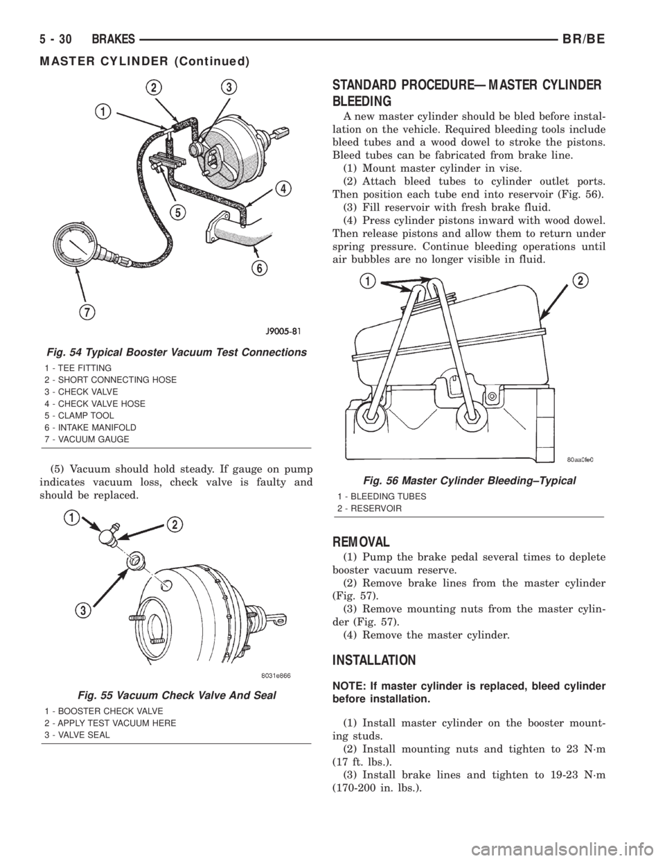
(5) Vacuum should hold steady. If gauge on pump
indicates vacuum loss, check valve is faulty and
should be replaced.
STANDARD PROCEDUREÐMASTER CYLINDER
BLEEDING
A new master cylinder should be bled before instal-
lation on the vehicle. Required bleeding tools include
bleed tubes and a wood dowel to stroke the pistons.
Bleed tubes can be fabricated from brake line.
(1) Mount master cylinder in vise.
(2) Attach bleed tubes to cylinder outlet ports.
Then position each tube end into reservoir (Fig. 56).
(3) Fill reservoir with fresh brake fluid.
(4) Press cylinder pistons inward with wood dowel.
Then release pistons and allow them to return under
spring pressure. Continue bleeding operations until
air bubbles are no longer visible in fluid.
REMOVAL
(1) Pump the brake pedal several times to deplete
booster vacuum reserve.
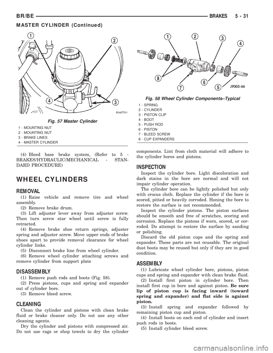
(2) Remove brake lines from the master cylinder
(Fig. 57).
(3) Remove mounting nuts from the master cylin-
der (Fig. 57).
(4) Remove the master cylinder.
INSTALLATION
NOTE: If master cylinder is replaced, bleed cylinder
before installation.
(1) Install master cylinder on the booster mount-
ing studs.
(2) Install mounting nuts and tighten to 23 N´m
(17 ft. lbs.).
(3) Install brake lines and tighten to 19-23 N´m
(170-200 in. lbs.).
Fig. 54 Typical Booster Vacuum Test Connections
1 - TEE FITTING
2 - SHORT CONNECTING HOSE
3 - CHECK VALVE
4 - CHECK VALVE HOSE
5 - CLAMP TOOL
6 - INTAKE MANIFOLD
7 - VACUUM GAUGE
Fig. 55 Vacuum Check Valve And Seal
1 - BOOSTER CHECK VALVE
2 - APPLY TEST VACUUM HERE
3 - VALVE SEAL
Fig. 56 Master Cylinder Bleeding±Typical
1 - BLEEDING TUBES
2 - RESERVOIR
5 - 30 BRAKESBR/BE
MASTER CYLINDER (Continued)
Page 302 of 2889
(4) Bleed base brake system, (Refer to 5 -
BRAKES/HYDRAULIC/MECHANICAL - STAN-
DARD PROCEDURE)
WHEEL CYLINDERS
REMOVAL
(1) Raise vehicle and remove tire and wheel
assembly.
(2) Remove brake drum.
(3) Lift adjuster lever away from adjuster screw.
Then turn screw star wheel until screw is fully
retracted.
(4) Remove brake shoe return springs, adjuster
spring and adjuster screw. Move upper ends of brake
shoes apart to provide removal clearance for wheel
cylinder links.
(5) Disconnect brake line from wheel cylinder.
(6) Remove wheel cylinder attaching screws and
remove cylinder from support plate
DISASSEMBLY
(1) Remove push rods and boots (Fig. 58).
(2) Press pistons, cups and spring and expander
out of cylinder bore.
(3) Remove bleed screw.
CLEANING
Clean the cylinder and pistons with clean brake
fluid or brake cleaner only. Do not use any other
cleaning agents.
Dry the cylinder and pistons with compressed air.
Do not use rags or shop towels to dry the cylindercomponents. Lint from cloth material will adhere to
the cylinder bores and pistons.
INSPECTION
Inspect the cylinder bore. Light discoloration and
dark stains in the bore are normal and will not
impair cylinder operation.
The cylinder bore can be lightly polished but only
with crocus cloth. Replace the cylinder if the bore is
scored, pitted or heavily corroded. Honing the bore to
restore the surface is not recommended.
Inspect the cylinder pistons. The piston surfaces
should be smooth and free of scratches, scoring and
corrosion. Replace the pistons if worn, scored, or cor-
roded. Do attempt to restore the surface by sanding
or polishing.
Discard the old piston cups and the spring and
expander. These parts are not reusable. The original
dust boots may be reused but only if they are in good
condition.
ASSEMBLY
(1) Lubricate wheel cylinder bore, pistons, piston
cups and spring and expander with clean brake fluid.
(2) Install first piston in cylinder bore. Then
install first cup in bore and against piston.Be sure
lip of piston cup is facing inward (toward
spring and expander) and flat side is against
piston.
(3) Install spring and expander followed by
remaining piston cup and piston.
(4) Install boots on each end of cylinder and insert
push rods in boots.
(5) Install cylinder bleed screw.
Fig. 57 Master Cylinder
1 - MOUNTING NUT
2 - MOUNTING NUT
3 - BRAKE LINES
4 - MASTER CYLINDER
Fig. 58 Wheel Cylinder Components±Typical
1 - SPRING
2 - CYLINDER
3 - PISTON CLIP
4 - BOOT
5 - PUSH ROD
6 - PISTON
7 - BLEED SCREW
8 - CUP EXPANDERS
BR/BEBRAKES 5 - 31
MASTER CYLINDER (Continued)