2001 DODGE RAM brake
[x] Cancel search: brakePage 560 of 2889
INSTRUMENT CLUSTER
TABLE OF CONTENTS
page page
INSTRUMENT CLUSTER
DESCRIPTION............................2
OPERATION.............................3
DIAGNOSIS AND TESTING..................6
INSTRUMENT CLUSTER..................6
REMOVAL..............................10
DISASSEMBLY...........................11
ASSEMBLY.............................13
INSTALLATION...........................14
ABS INDICATOR
DESCRIPTION...........................14
OPERATION.............................14
AIRBAG INDICATOR
DESCRIPTION...........................15
OPERATION.............................15
BRAKE/PARK BRAKE INDICATOR
DESCRIPTION...........................16
OPERATION.............................16
DIAGNOSIS AND TESTING.................16
BRAKE INDICATOR.....................16
CHECK GAUGES INDICATOR
DESCRIPTION...........................17
OPERATION.............................17
CRUISE INDICATOR
DESCRIPTION...........................18
OPERATION.............................18
ENGINE TEMPERATURE GAUGE
DESCRIPTION...........................19
OPERATION.............................19
FUEL GAUGE
DESCRIPTION...........................20
OPERATION.............................20
GEAR SELECTOR INDICATOR
DESCRIPTION...........................21
OPERATION.............................21
HIGH BEAM INDICATOR
DESCRIPTION...........................21
OPERATION.............................22
DIAGNOSIS AND TESTING.................22
HIGH BEAM INDICATOR.................22
LOW FUEL INDICATOR
DESCRIPTION...........................23
OPERATION.............................23
MALFUNCTION INDICATOR LAMP (MIL)
DESCRIPTION...........................24
OPERATION.............................24
ODOMETER
DESCRIPTION...........................24
OPERATION.............................25OIL PRESSURE GAUGE
DESCRIPTION...........................25
OPERATION.............................26
OVERDRIVE OFF INDICATOR
DESCRIPTION...........................27
OPERATION.............................27
SEATBELT INDICATOR
DESCRIPTION...........................27
OPERATION.............................27
SERVICE REMINDER INDICATOR
DESCRIPTION...........................28
OPERATION.............................28
SHIFT INDICATOR (TRANSFER CASE)
DESCRIPTION...........................29
OPERATION.............................29
DIAGNOSIS AND TESTING.................29
FOUR-WHEEL DRIVE INDICATOR..........29
SPEEDOMETER
DESCRIPTION...........................30
OPERATION.............................30
TACHOMETER
DESCRIPTION...........................30
OPERATION.............................31
TRANSMISSION OVERTEMP INDICATOR
DESCRIPTION...........................31
OPERATION.............................31
TURN SIGNAL INDICATORS
DESCRIPTION...........................32
OPERATION.............................32
DIAGNOSIS AND TESTING.................32
TURN SIGNAL INDICATORS..............32
UPSHIFT INDICATOR
DESCRIPTION...........................33
OPERATION.............................33
VOLTAGE GAUGE
DESCRIPTION...........................33
OPERATION.............................34
WAIT-TO-START INDICATOR
DESCRIPTION...........................34
OPERATION.............................35
WASHER FLUID INDICATOR
DESCRIPTION...........................35
OPERATION.............................35
DIAGNOSIS AND TESTING.................36
WASHER FLUID INDICATOR..............36
WATER-IN-FUEL INDICATOR
DESCRIPTION...........................36
OPERATION.............................37
BR/BEINSTRUMENT CLUSTER 8J - 1
Page 561 of 2889
INSTRUMENT CLUSTER
DESCRIPTION
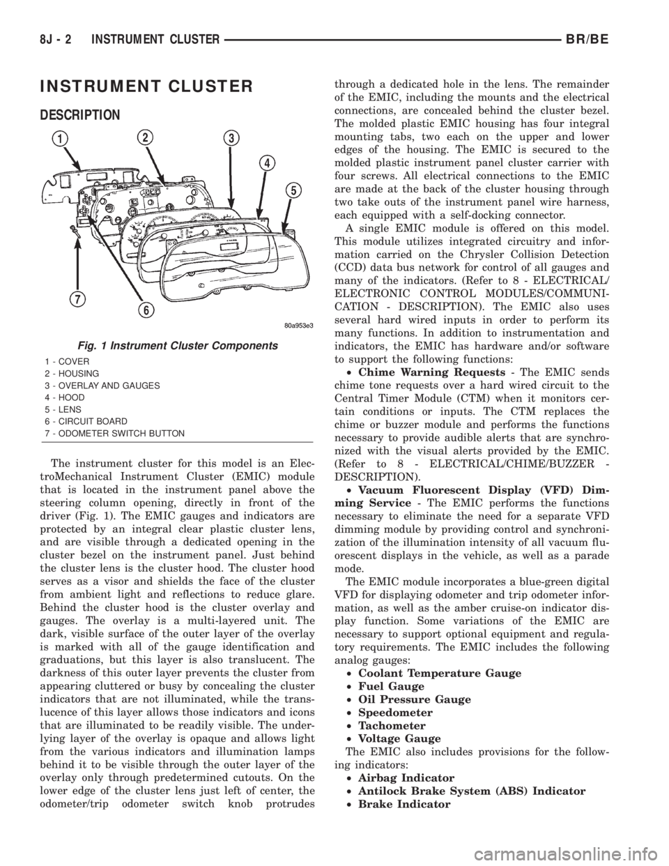
The instrument cluster for this model is an Elec-
troMechanical Instrument Cluster (EMIC) module
that is located in the instrument panel above the
steering column opening, directly in front of the
driver (Fig. 1). The EMIC gauges and indicators are
protected by an integral clear plastic cluster lens,
and are visible through a dedicated opening in the
cluster bezel on the instrument panel. Just behind
the cluster lens is the cluster hood. The cluster hood
serves as a visor and shields the face of the cluster
from ambient light and reflections to reduce glare.
Behind the cluster hood is the cluster overlay and
gauges. The overlay is a multi-layered unit. The
dark, visible surface of the outer layer of the overlay
is marked with all of the gauge identification and
graduations, but this layer is also translucent. The
darkness of this outer layer prevents the cluster from
appearing cluttered or busy by concealing the cluster
indicators that are not illuminated, while the trans-
lucence of this layer allows those indicators and icons
that are illuminated to be readily visible. The under-
lying layer of the overlay is opaque and allows light
from the various indicators and illumination lamps
behind it to be visible through the outer layer of the
overlay only through predetermined cutouts. On the
lower edge of the cluster lens just left of center, the
odometer/trip odometer switch knob protrudesthrough a dedicated hole in the lens. The remainder
of the EMIC, including the mounts and the electrical
connections, are concealed behind the cluster bezel.
The molded plastic EMIC housing has four integral
mounting tabs, two each on the upper and lower
edges of the housing. The EMIC is secured to the
molded plastic instrument panel cluster carrier with
four screws. All electrical connections to the EMIC
are made at the back of the cluster housing through
two take outs of the instrument panel wire harness,
each equipped with a self-docking connector.
A single EMIC module is offered on this model.
This module utilizes integrated circuitry and infor-
mation carried on the Chrysler Collision Detection
(CCD) data bus network for control of all gauges and
many of the indicators. (Refer to 8 - ELECTRICAL/
ELECTRONIC CONTROL MODULES/COMMUNI-
CATION - DESCRIPTION). The EMIC also uses
several hard wired inputs in order to perform its
many functions. In addition to instrumentation and
indicators, the EMIC has hardware and/or software
to support the following functions:
²Chime Warning Requests- The EMIC sends
chime tone requests over a hard wired circuit to the
Central Timer Module (CTM) when it monitors cer-
tain conditions or inputs. The CTM replaces the
chime or buzzer module and performs the functions
necessary to provide audible alerts that are synchro-
nized with the visual alerts provided by the EMIC.
(Refer to 8 - ELECTRICAL/CHIME/BUZZER -
DESCRIPTION).
²Vacuum Fluorescent Display (VFD) Dim-
ming Service- The EMIC performs the functions
necessary to eliminate the need for a separate VFD
dimming module by providing control and synchroni-
zation of the illumination intensity of all vacuum flu-
orescent displays in the vehicle, as well as a parade
mode.
The EMIC module incorporates a blue-green digital
VFD for displaying odometer and trip odometer infor-
mation, as well as the amber cruise-on indicator dis-
play function. Some variations of the EMIC are
necessary to support optional equipment and regula-
tory requirements. The EMIC includes the following
analog gauges:
²Coolant Temperature Gauge
²Fuel Gauge
²Oil Pressure Gauge
²Speedometer
²Tachometer
²Voltage Gauge
The EMIC also includes provisions for the follow-
ing indicators:
²Airbag Indicator
²Antilock Brake System (ABS) Indicator
²Brake Indicator
Fig. 1 Instrument Cluster Components
1 - COVER
2 - HOUSING
3 - OVERLAY AND GAUGES
4 - HOOD
5 - LENS
6 - CIRCUIT BOARD
7 - ODOMETER SWITCH BUTTON
8J - 2 INSTRUMENT CLUSTERBR/BE
Page 564 of 2889
The VFD is diagnosed using the EMIC self-diag-
nostic actuator test. (Refer to 8 - ELECTRICAL/IN-
STRUMENT CLUSTER - DIAGNOSIS AND
TESTING). Proper testing of the CCD data bus and
the data bus message inputs to the EMIC that con-
trol some of the VFD functions requires the use of a
DRBIIItscan tool. Refer to the appropriate diagnos-
tic information. Specific operation details for the
odometer and trip odometer functions of the VFD
may be found elsewhere in this service manual.
INDICATORS
Indicators are located in various positions within
the EMIC and are all connected to the EMIC circuit
board. The four-wheel drive indicator, high beam
indicator, washer fluid indicator, turn signal indica-
tors, and wait-to-start indicator are hard wired. The
brake indicator is controlled by CCD data bus mes-
sages from the Controller Anti-lock Brake (CAB) and
the hard wired park brake switch input to the EMIC.
The seatbelt indicator is controlled by the EMIC pro-
gramming, CCD data bus messages from the Airbag
Control Module (ACM), and the hard wired seat belt
switch input to the EMIC. The Malfunction Indicator
Lamp (MIL) is normally controlled by CCD data bus
messages from the Powertrain Control Module
(PCM); however, if the EMIC loses CCD data bus
communications, the EMIC circuitry will automati-
cally turn the MIL on, and flash the odometer VFD
on and off repeatedly until CCD data bus communi-
cation is restored. The EMIC uses CCD data bus
messages from the Powertrain Control Module
(PCM), the diesel engine only Engine Control Module
(ECM), the ACM, and the CAB to control all of the
remaining indicators. Different indicators are con-
trolled by different strategies; some receive fused
ignition switch output from the EMIC circuitry clus-
ter and have a switched ground, while others are
grounded through the EMIC circuitry and have a
switched battery feed.
In addition, certain indicators in this instrument
cluster are programmable or configurable. This fea-
ture allows the programmable indicators to be acti-
vated or deactivated with a DRBIIItscan tool, while
the configurable indicators will be automatically
enabled or disabled by the EMIC circuitry for com-
patibility with certain optional equipment. The only
programmable indicator for this model is the upshift
indicator. The cruise indicator, four-wheel drive indi-
cator, overdrive-off indicator, service reminder indica-
tor, and the transmission overtemp indicator are
automatically configured, either electronically or
mechanically.The hard wired indicators are diagnosed using con-
ventional diagnostic methods. The EMIC and CCD
bus message controlled indicator lamps are diagnosed
using the EMIC self-diagnostic actuator test. (Refer
to 8 - ELECTRICAL/INSTRUMENT CLUSTER -
DIAGNOSIS AND TESTING). Proper testing of the
CCD data bus and the data bus message inputs to
the EMIC that control each indicator lamp require
the use of a DRBIIItscan tool. Refer to the appro-
priate diagnostic information. Specific operation
details for each indicator may be found elsewhere in
this service manual.
CLUSTER ILLUMINATION
The EMIC has several illumination lamps that are
illuminated when the exterior lighting is turned on
with the headlamp switch. The illumination bright-
ness of these lamps is adjusted by the panel lamps
dimmer rheostat when the headlamp switch thumb-
wheel is rotated (down to dim, up to brighten). The
illumination lamps receive battery current through
the panel lamps dimmer rheostat and a fuse in the
JB on a fused panel lamps dimmer switch signal cir-
cuit. The illumination lamps are grounded at all
times.
In addition, an analog/digital (A/D) converter in
the EMIC converts the analog panel lamps dimmer
rheostat input from the headlamp switch to a digital
dimming level signal for controlling the lighting level
of the VFD. The EMIC also broadcasts this digital
dimming information as a message over the CCD
data bus for use by the Compass Mini-Trip Computer
(CMTC) in synchronizing the lighting level of its
VFD with that of the EMIC. The headlamp switch
thumbwheel also has a Parade position to provide a
parade mode. The EMIC monitors the request for
this mode through a hard wired day brightness sense
circuit input from the headlamp switch. In this mode,
the EMIC will override the selected panel dimmer
switch signal and send a message over the CCD data
bus to illuminate all vacuum fluorescent displays at
full brightness for easier visibility when driving in
daylight with the exterior lighting turned on. The
parade mode has no effect on the incandescent bulb
illumination intensity.
The hard wired cluster illumination lamps are
diagnosed using conventional diagnostic methods.
Proper testing of the VFD dimming level and the
CCD data bus dimming level message functions
requires the use of a DRBIIItscan tool. Refer to the
appropriate diagnostic information.
BR/BEINSTRUMENT CLUSTER 8J - 5
INSTRUMENT CLUSTER (Continued)
Page 566 of 2889
(7) Turn the ignition switch to the Off position.
Disconnect and isolate the battery negative cable.
Reinstall the instrument cluster. Reconnect the bat-
tery negative cable. Turn the ignition switch to the
On position. Set the park brake. The brake indicator
in the instrument cluster should light. If OK, go to
Step 8. If not OK, go to Step 9.
(8) Turn the ignition switch to the Off position.
Turn on the park lamps and adjust the panel lamps
dimmer thumbwheel in the headlamp switch to the
full bright position. The cluster illumination lamps
should light. If OK, go to Step 10. If not OK, repair
the open ground circuit (Z3) between the instrument
cluster and ground (G201) as required.
(9) Turn the ignition switch to the Off position.
Disconnect and isolate the battery negative cable.
Remove the instrument cluster. Connect the battery
negative cable. Turn the ignition switch to the On
position. Check for battery voltage at the fused igni-
tion switch output (st-run) circuit cavity of the
instrument panel wire harness connector (Connector
C1). If OK, refer to ACTUATOR TEST . If not OK,
repair the open fused ignition switch output (st-run)
circuit between the instrument cluster and the JB as
required.
(10) Disconnect and isolate the battery negative
cable. Remove the instrument cluster. Check for con-
tinuity between the ground circuit (Z2) cavity of the
instrument panel wire harness connector (Connector
C1) and a good ground. There should be continuity. If
OK, refer to ACTUATOR TEST . If not OK, repair
the open ground circuit to ground (G200) as required.
ACTUATOR TEST
WARNING: ON VEHICLES EQUIPPED WITH AIR-
BAGS, DISABLE THE AIRBAG SYSTEM BEFORE
ATTEMPTING ANY STEERING WHEEL, STEERING
COLUMN, OR INSTRUMENT PANEL COMPONENT
DIAGNOSIS OR SERVICE. DISCONNECT AND ISO-
LATE THE BATTERY NEGATIVE (GROUND) CABLE,
THEN WAIT TWO MINUTES FOR THE AIRBAG SYS-
TEM CAPACITOR TO DISCHARGE BEFORE PER-
FORMING FURTHER DIAGNOSIS OR SERVICE. THIS
IS THE ONLY SURE WAY TO DISABLE THE AIRBAG
SYSTEM. FAILURE TO TAKE THE PROPER PRE-CAUTIONS COULD RESULT IN ACCIDENTAL AIR-
BAG DEPLOYMENT AND POSSIBLE PERSONAL
INJURY.
The instrument cluster actuator test will put the
instrument cluster into its self-diagnostic mode. In
this mode the instrument cluster can perform a self-
diagnostic test that will confirm that the instrument
cluster circuitry, the gauges, and the CCD data bus
message-controlled indicators are capable of operat-
ing as designed. During the actuator test the instru-
ment cluster circuitry position each of the gauge
needles at various calibration points, illuminate each
of the segments in the Vacuum-Fluorescent Display
(VFD), and turn all of the CCD data bus message-
controlled indicators on and off.
Successful completion of the actuator test will con-
firm that the instrument cluster is operational. How-
ever, there may still be a problem with the CCD data
bus, the Powertrain Control Module (PCM), the
Engine Control Module (ECM), the Airbag Control
Module (ACM), the Controller Anti-lock Brake (CAB),
or the inputs to one of these electronic control mod-
ules. Use a DRBIIItscan tool to diagnose these com-
ponents. Refer to the appropriate diagnostic
information.
(1) Begin the test with the ignition switch in the
Off position.
(2) Depress the odometer/trip odometer switch but-
ton.
(3) While still holding the odometer/trip odometer
switch button depressed, turn the ignition switch to
the On position, but do not start the engine.
(4) Keep the odometer/trip odometer switch button
depressed for about ten seconds, untilCHEC
appears in the odometer display, then release the
odometer/trip odometer switch button.
(5) A series of three-digit numeric failure messages
may appear in the odometer display, depending upon
the failure mode. If a failure message appears, refer
to the Instrument Cluster Failure Message chart for
the description and proper correction. If no failure
message appears, the actuator test will proceed as
described in Step 6.
BR/BEINSTRUMENT CLUSTER 8J - 7
INSTRUMENT CLUSTER (Continued)
Page 573 of 2889
INSTALLATION
WARNING: ON VEHICLES EQUIPPED WITH AIR-
BAGS, DISABLE THE AIRBAG SYSTEM BEFORE
ATTEMPTING ANY STEERING WHEEL, STEERING
COLUMN, OR INSTRUMENT PANEL COMPONENT
DIAGNOSIS OR SERVICE. DISCONNECT AND ISO-
LATE THE BATTERY NEGATIVE (GROUND) CABLE,
THEN WAIT TWO MINUTES FOR THE AIRBAG SYS-
TEM CAPACITOR TO DISCHARGE BEFORE PER-
FORMING FURTHER DIAGNOSIS OR SERVICE. THIS
IS THE ONLY SURE WAY TO DISABLE THE AIRBAG
SYSTEM. FAILURE TO TAKE THE PROPER PRE-
CAUTIONS COULD RESULT IN ACCIDENTAL AIR-
BAG DEPLOYMENT AND POSSIBLE PERSONAL
INJURY.
(1) Position the instrument cluster to the instru-
ment panel.
(2) If the vehicle is equipped with an automatic
transmission, position the gear selector indicator onto
the back of the cluster housing (Fig. 3).
(3) If the vehicle is equipped with an automatic
transmission, install and tighten the two screws that
secure the gear selector indicator mechanism to the
back of the cluster housing. Tighten the screws to 2.2
N´m (20 in. lbs.).
(4) Align the instrument cluster with the cluster
opening in the instrument panel and push the cluster
firmly and evenly into place. The instrument panel
wire harness has two self-docking connectors that
will be automatically aligned with, and connected to
the instrument cluster connector receptacles when
the cluster is properly installed in the instrument
panel.
(5) Install and tighten the four screws that secure
the instrument cluster to the instrument panel (Fig.
2). Tighten the screws to 2.2 N´m (20 in. lbs.).
(6) Reinstall the cluster bezel onto the instrument
panel. (Refer to 23 - BODY/INSTRUMENT PANEL/
CLUSTER BEZEL - INSTALLATION).
(7) If the vehicle is equipped with an automatic
transmission, confirm proper operation of the gear
selector indicator. Calibrate the indicator, if required.
(Refer to 19 - STEERING/COLUMN - INSTALLA-
TION).
(8) Reconnect the battery negative cable.
NOTE: Some of the indicators in this instrument
cluster are either programmable (upshift indicator)
or automatically configured (cruise, overdrive-off,
and transmission overtemp indicators) when the
cluster is connected to the vehicle electrical sys-
tem. This feature allows those indicator lamps to be
enabled or disabled for compatibility with certain
optional equipment. If a new instrument cluster is
being installed, use a DRBIIITscan tool to programthe instrument cluster with the proper vehicle
equipment option setting to enable and/or disable
the upshift indicator lamp. Refer to the appropriate
diagnostic information.
ABS INDICATOR
DESCRIPTION
An Antilock Brake System (ABS) indicator is stan-
dard equipment on all instrument clusters. This indi-
cator serves both the standard equipment Rear
Wheel Anti-Lock (RWAL) and optional equipment
4-Wheel Anti-Lock (4WAL) brake systems. The ABS
indicator is located near the lower edge of the instru-
ment cluster overlay, to the left of center. The ABS
indicator consists of a stencilled cutout of the Inter-
national Control and Display Symbol icon for ªFail-
ure of Anti-lock Braking Systemº in the opaque layer
of the instrument cluster overlay. The dark outer
layer of the overlay prevents the indicator from being
clearly visible when it is not illuminated. An amber
lens behind the cutout in the opaque layer of the
overlay causes the icon to appear in amber through
the translucent outer layer of the overlay when it is
illuminated from behind by a Light Emitting Diode
(LED) soldered onto the instrument cluster electronic
circuit board. The ABS indicator is serviced as a unit
with the instrument cluster.
OPERATION
The ABS indicator gives an indication to the vehi-
cle operator when the ABS system is faulty or inop-
erative. This indicator is controlled by a transistor on
the instrument cluster circuit board based upon clus-
ter programming and electronic messages received by
the cluster from the Controller Antilock Brake (CAB)
over the Chrysler Collision Detection (CCD) data bus.
The ABS indicator Light Emitting Diode (LED)
receives battery current on the instrument cluster
electronic circuit board through the fused ignition
switch output (st-run) circuit whenever the ignition
switch is in the On or Start positions; therefore, the
LED will always be off when the ignition switch is in
any position except On or Start. The LED only illu-
minates when it is provided a path to ground by the
instrument cluster transistor. The instrument cluster
will turn on the ABS indicator for the following rea-
sons:
²Bulb Test- Each time the ignition switch is
turned to the On position the ABS indicator is illu-
minated by the cluster for about two seconds as a
bulb test.
²ABS Lamp-On Message- Each time the clus-
ter receives a lamp-on message from the CAB, the
8J - 14 INSTRUMENT CLUSTERBR/BE
INSTRUMENT CLUSTER (Continued)
Page 574 of 2889

ABS indicator will be illuminated. The indicator
remains illuminated until the cluster receives a
lamp-off message from the CAB, or until the ignition
switch is turned to the Off position, whichever occurs
first.
²Communication Error- If the cluster receives
no lamp-on or lamp-off messages from the CAB for
six consecutive seconds, the ABS indicator is illumi-
nated. The indicator remains illuminated until the
cluster receives a valid message from the CAB, or
until the ignition switch is turned to the Off position,
whichever occurs first.
²Actuator Test- Each time the instrument clus-
ter is put through the actuator test, the ABS indica-
tor will be turned on during the bulb check portion of
the test to confirm the functionality of the LED and
the cluster control circuitry.
²ABS Diagnostic Test- The ABS indicator is
blinked on and off by lamp-on and lamp-off messages
from the CAB during the performance of the ABS
diagnostic tests.
The CAB continually monitors the ABS circuits
and sensors to decide whether the system is in good
operating condition. The CAB then sends the proper
lamp-on or lamp-off messages to the instrument clus-
ter. If the CAB sends a lamp-on message after the
bulb test, it indicates that the CAB has detected a
system malfunction and/or that the ABS system has
become inoperative. The CAB will store a Diagnostic
Trouble Code (DTC) for any malfunction it detects.
Each time the ABS indicator fails to light due to an
open or short in the cluster ABS indicator circuit, the
cluster sends a message notifying the CAB of the
condition, and the CAB will store a DTC. For proper
diagnosis of the antilock brake system, the CAB, the
CCD data bus, or the message inputs to the instru-
ment cluster that control the ABS indicator, a
DRBIIItscan tool is required. Refer to the appropri-
ate diagnostic information.
AIRBAG INDICATOR
DESCRIPTION
An airbag indicator is standard equipment on all
instrument clusters. However, on vehicles not
equipped with airbags, this indicator is electronically
disabled. The airbag indicator is located near the
lower edge of the instrument cluster overlay, to the
right of center. The airbag indicator consists of a
stenciled cutout of the word ªAIRBAGº in the opaque
layer of the instrument cluster overlay. The dark
outer layer of the overlay prevents the indicator from
being clearly visible when it is not illuminated. A red
lens behind the cutout in the opaque layer of the
overlay causes the ªAIRBAGº text to appear in redthrough the translucent outer layer of the overlay
when it is illuminated from behind by a Light Emit-
ting Diode (LED) soldered onto the instrument clus-
ter electronic circuit board. The airbag indicator is
serviced as a unit with the instrument cluster.
OPERATION
The airbag indicator gives an indication to the
vehicle operator when the airbag system is faulty or
inoperative. The airbag indicator is controlled by a
transistor on the instrument cluster circuit board
based upon cluster programming and electronic mes-
sages received by the cluster from the Airbag Control
Module (ACM) over the Chrysler Collision Detection
(CCD) data bus. The airbag indicator Light Emitting
Diode (LED) receives battery current on the instru-
ment cluster electronic circuit board through the
fused ignition switch output (st-run) circuit whenever
the ignition switch is in the On or Start positions;
therefore, the indicator will always be off when the
ignition switch is in any position except On or Start.
The LED only illuminates when it is provided a path
to ground by the instrument cluster transistor. The
instrument cluster will turn on the airbag indicator
for the following reasons:
²Bulb Test- Each time the ignition switch is
turned to the On position the airbag indicator is illu-
minated for about seven seconds. The first two sec-
onds is the cluster bulb test function, and the
remainder is the ACM bulb test function.
²ACM Lamp-On Message- Each time the clus-
ter receives a lamp-on message from the ACM, the
airbag indicator will be illuminated. The indicator
remains illuminated for about twelve seconds or until
the cluster receives a lamp-off message from the
ACM, whichever is longer.
²Communication Error- If the cluster receives
no airbag messages for three consecutive seconds, the
airbag indicator is illuminated. The indicator
remains illuminated for about twelve seconds or until
the cluster receives a single lamp-off message from
the ACM, whichever is longer.
²Actuator Test- Each time the cluster is put
through the actuator test, the airbag indicator will be
turned on during the bulb check portion of the test to
confirm the functionality of the LED and the cluster
control circuitry.
The ACM continually monitors the airbag system
circuits and sensors to decide whether the system is
in good operating condition. The ACM then sends the
proper lamp-on or lamp-off messages to the instru-
ment cluster. If the ACM sends a lamp-on message
after the bulb test, it indicates that the ACM has
detected a system malfunction and/or that the air-
bags may not deploy when required, or may deploy
when not required. The ACM will store a Diagnostic
BR/BEINSTRUMENT CLUSTER 8J - 15
ABS INDICATOR (Continued)
Page 575 of 2889
Trouble Code (DTC) for any malfunction it detects.
Each time the airbag indicator fails to illuminate due
to an open or short in the cluster airbag indicator cir-
cuit, the cluster sends a message notifying the ACM
of the condition, the ACM will store a DTC, and the
cluster begins blinking the seat belt indicator. (Refer
to 8 - ELECTRICAL/INSTRUMENT CLUSTER/
SEATBELT INDICATOR - OPERATION). For proper
diagnosis of the airbag system, the ACM, the CCD
data bus, or the message inputs to the instrument
cluster that control the airbag indicator, a DRBIIIt
scan tool is required. Refer to the appropriate diag-
nostic information.
BRAKE/PARK BRAKE
INDICATOR
DESCRIPTION
A brake indicator is standard equipment on all
instrument clusters. The brake indicator is located
near the lower edge of the instrument cluster overlay,
to the right of center. The brake indicator consists of
a stenciled cutout of the word ªBRAKEº in the
opaque layer of the instrument cluster overlay. The
dark outer layer of the overlay prevents the indicator
from being clearly visible when it is not illuminated.
A red lens behind the cutout in the opaque layer of
the overlay causes the ªBRAKEº text to appear in
red through the translucent outer layer of the over-
lay when it is illuminated from behind by a Light
Emitting Diode (LED) soldered onto the instrument
cluster electronic circuit board. The brake indicator is
serviced as a unit with the instrument cluster.
OPERATION
The brake indicator gives an indication to the vehi-
cle operator when the parking brake is applied, or
when there are certain brake hydraulic system mal-
functions. This indicator is controlled by a transistor
on the instrument cluster circuit board based upon a
hard wired input to the instrument cluster, cluster
programming, and electronic messages received by
the cluster from the Controller Antilock Brake (CAB)
over the Chrysler Collision Detection (CCD) data bus.
The brake indicator Light Emitting Diode (LED)
receives battery current on the instrument cluster
electronic circuit board through the fused ignition
switch output (st-run) circuit whenever the ignition
switch is in the On or Start positions; therefore, the
LED will always be off when the ignition switch is in
any position except On or Start. The LED only illu-
minates when it is provided a path to ground by the
instrument cluster transistor. The instrument cluster
will turn on the brake indicator for the following rea-
sons:²Bulb Test- Each time the ignition switch is
turned to the On position the brake indicator is illu-
minated by the instrument cluster for about four sec-
onds as a bulb test.
²Park Brake-On- If the park brake is applied
or not fully released with the ignition switch in the
On position, the brake indicator is illuminated solid.
The brake indicator will blink on and off repeatedly
when the park brake is applied or not fully released
and the ignition switch is in the On position if a
vehicle with an automatic transmission is not in
Park or Neutral, or if the engine is running on vehi-
cles with a manual transmission.
²Brake Lamp-On Message- Each time the
cluster receives a lamp-on message from the CAB,
the brake indicator will be illuminated. The indicator
remains illuminated until the cluster receives a
lamp-off message from the CAB, or until the ignition
switch is turned to the Off position, whichever occurs
first.
²Actuator Test- Each time the instrument clus-
ter is put through the actuator test, the brake indi-
cator will be turned on during the bulb check portion
of the test to confirm the functionality of the LED
and the cluster control circuitry.
The park brake switch on the park brake pedal
mechanism provides a hard wired ground input to
the instrument cluster circuitry through the park
brake switch sense circuit whenever the park brake
is applied or not fully released. The CAB continually
monitors the brake pressure switch on the brake
combination valve to determine if the pressures in
the two halves of the split brake hydraulic system
are unequal. The CAB then sends the proper lamp-on
or lamp-off messages to the instrument cluster. If the
CAB sends a lamp-on message after the bulb test, it
indicates that the CAB has detected a brake hydrau-
lic system malfunction and/or that the ABS system
has become inoperative. The CAB will store a Diag-
nostic Trouble Code (DTC) for any malfunction it
detects. The park brake switch input to the instru-
ment cluster can be diagnosed using conventional
diagnostic tools and methods. For proper diagnosis of
the antilock brake system, the CAB, the CCD data
bus, or the message inputs to the instrument cluster
that control the brake indicator, a DRBIIItscan tool
is required. Refer to the appropriate diagnostic infor-
mation.
DIAGNOSIS AND TESTING - BRAKE INDICATOR
The diagnosis found here addresses an inoperative
brake indicator condition. If the brake indicator
comes on or stays on with the ignition switch in the
On position and the park brake released, or comes on
while driving, the brake system must be diagnosed
and repaired prior to performing the following tests.
8J - 16 INSTRUMENT CLUSTERBR/BE
AIRBAG INDICATOR (Continued)
Page 576 of 2889
(Refer to 5 - BRAKES - DIAGNOSIS AND TEST-
ING). If no brake system problem is found, the fol-
lowing procedure will help locate a faulty park brake
switch or park brake switch sense circuit. Refer to
the appropriate wiring information. The wiring infor-
mation includes wiring diagrams, proper wire and
connector repair procedures, details of wire harness
routing and retention, connector pin-out information
and location views for the various wire harness con-
nectors, splices and grounds.
WARNING: ON VEHICLES EQUIPPED WITH AIR-
BAGS, DISABLE THE AIRBAG SYSTEM BEFORE
ATTEMPTING ANY STEERING WHEEL, STEERING
COLUMN, OR INSTRUMENT PANEL COMPONENT
DIAGNOSIS OR SERVICE. DISCONNECT AND ISO-
LATE THE BATTERY NEGATIVE (GROUND) CABLE,
THEN WAIT TWO MINUTES FOR THE AIRBAG SYS-
TEM CAPACITOR TO DISCHARGE BEFORE PER-
FORMING FURTHER DIAGNOSIS OR SERVICE. THIS
IS THE ONLY SURE WAY TO DISABLE THE AIRBAG
SYSTEM. FAILURE TO TAKE THE PROPER PRE-
CAUTIONS COULD RESULT IN ACCIDENTAL AIR-
BAG DEPLOYMENT AND POSSIBLE PERSONAL
INJURY.
(1) Disconnect and isolate the battery negative
cable. Disconnect the instrument panel wire harness
connector for the park brake switch from the switch
terminal. With the park brake released, check for
continuity between the park brake switch terminal
and a good ground. There should be no continuity. If
OK, go to Step 2. If not OK, adjust or replace the
faulty park brake switch.
(2) Remove the instrument cluster from the instru-
ment panel. With the park brake switch still discon-
nected, check for continuity between the park brake
switch sense circuit cavity of the instrument panel
wire harness connector for the park brake switch and
a good ground. There should be no continuity. If OK,
go to Step 3. If not OK, repair the shorted park
brake switch sense circuit between the park brake
switch and the instrument cluster as required.
(3) Check for continuity between the park brake
switch sense circuit cavities of the instrument panel
wire harness connector for the park brake switch and
the instrument panel wire harness connector (Con-
nector C1) for the instrument cluster. There should
be continuity. If OK, proceed with diagnosis of the
instrument cluster. (Refer to 8 - ELECTRICAL/IN-
STRUMENT CLUSTER - DIAGNOSIS AND TEST-
ING). If not OK, repair the open park brake switch
sense circuit between the park brake switch and the
instrument cluster as required.CHECK GAUGES INDICATOR
DESCRIPTION
A check gauges indicator is standard equipment on
all instrument clusters. The check gauges indicator is
located on the lower edge of the instrument cluster
overlay, to the right of center. The check gauges indi-
cator consists of a stenciled cutout of the words
ªCHECK GAGESº in the opaque layer of the instru-
ment cluster overlay. The dark outer layer of the
overlay prevents the indicator from being clearly vis-
ible when the it is not illuminated. A red lens behind
the cutout in the opaque layer of the overlay causes
the ªCHECK GAGESº text to appear in red through
the translucent outer layer of the overlay when the
indicator is illuminated from behind by a Light Emit-
ting Diode (LED) soldered onto the instrument clus-
ter electronic circuit board. The check gauges
indicator is serviced as a unit with the instrument
cluster.
OPERATION
The check gauges indicator gives an indication to
the vehicle operator when certain instrument cluster
gauge readings reflect a condition requiring immedi-
ate attention. This indicator is controlled by a tran-
sistor on the instrument cluster circuit board based
upon the cluster programming and electronic mes-
sages received by the cluster from the Powertrain
Control Module (PCM) over the Chrysler Collision
Detection (CCD) data bus. The check gauges indica-
tor Light Emitting Diode (LED) receives battery cur-
rent on the instrument cluster electronic circuit
board through the fused ignition switch output (st-
run) circuit whenever the ignition switch is in the On
or Start positions; therefore, the LED will always be
off when the ignition switch is in any position except
On or Start. The LED only illuminates when it is
provided a path to ground by the instrument cluster
transistor. The instrument cluster will turn on the
check gauges indicator for the following reasons:
²Bulb Test- Each time the ignition switch is
turned to the On position the check gauges indicator
is illuminated for about two seconds as a bulb test.
²Engine Temperature High Message- Each
time the cluster receives a message from the PCM
indicating the engine coolant temperature of a gaso-
line engine is about 122É C (253É F) or higher, or a
diesel engine is about 112É C (233É F) or higher, the
check gauges indicator will be illuminated. The indi-
cator remains illuminated until the cluster receives a
message from the PCM indicating that the tempera-
ture of a gasoline engine is about 119É C (246É F) or
lower, a diesel engine is about 109É C (226É F) or
lower, or until the ignition switch is turned to the Off
position, whichever occurs first.
BR/BEINSTRUMENT CLUSTER 8J - 17
BRAKE/PARK BRAKE INDICATOR (Continued)