2001 DODGE RAM battery location
[x] Cancel search: battery locationPage 1366 of 2889
INSPECTION
Inspect oil drain plug and plug hole for stripped or
damaged threads. Repair as necessary.
Inspect oil pan mounting flange for bends or distor-
tion. Straighten flange, if necessary.
INSTALLATION
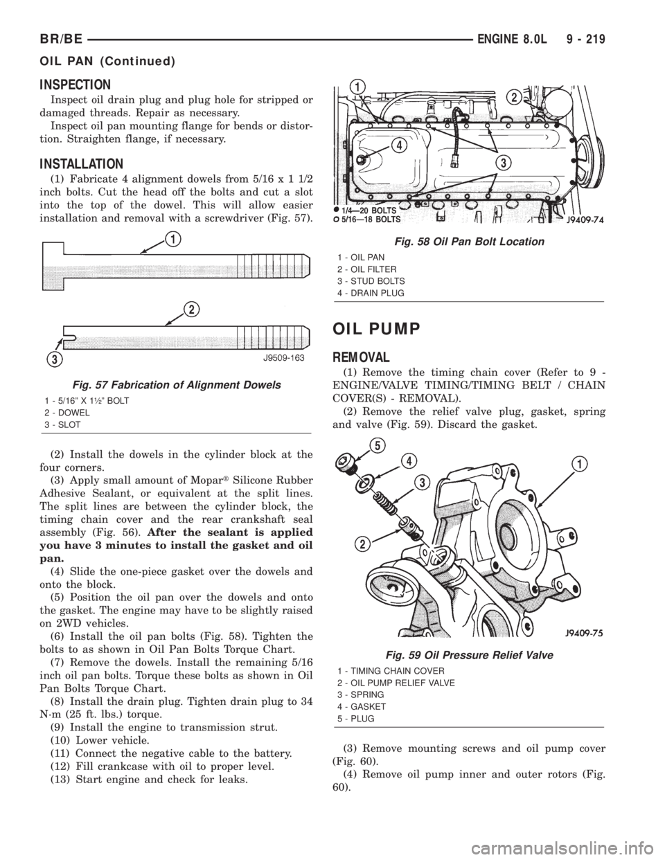
(1) Fabricate 4 alignment dowels from 5/16x11/2
inch bolts. Cut the head off the bolts and cut a slot
into the top of the dowel. This will allow easier
installation and removal with a screwdriver (Fig. 57).
(2) Install the dowels in the cylinder block at the
four corners.
(3) Apply small amount of MopartSilicone Rubber
Adhesive Sealant, or equivalent at the split lines.
The split lines are between the cylinder block, the
timing chain cover and the rear crankshaft seal
assembly (Fig. 56).After the sealant is applied
you have 3 minutes to install the gasket and oil
pan.
(4) Slide the one-piece gasket over the dowels and
onto the block.
(5) Position the oil pan over the dowels and onto
the gasket. The engine may have to be slightly raised
on 2WD vehicles.
(6) Install the oil pan bolts (Fig. 58). Tighten the
bolts to as shown in Oil Pan Bolts Torque Chart.
(7) Remove the dowels. Install the remaining 5/16
inch oil pan bolts. Torque these bolts as shown in Oil
Pan Bolts Torque Chart.
(8) Install the drain plug. Tighten drain plug to 34
N´m (25 ft. lbs.) torque.
(9) Install the engine to transmission strut.
(10) Lower vehicle.
(11) Connect the negative cable to the battery.
(12) Fill crankcase with oil to proper level.
(13) Start engine and check for leaks.
OIL PUMP
REMOVAL
(1) Remove the timing chain cover (Refer to 9 -
ENGINE/VALVE TIMING/TIMING BELT / CHAIN
COVER(S) - REMOVAL).
(2) Remove the relief valve plug, gasket, spring
and valve (Fig. 59). Discard the gasket.
(3) Remove mounting screws and oil pump cover
(Fig. 60).
(4) Remove oil pump inner and outer rotors (Fig.
60).
Fig. 57 Fabrication of Alignment Dowels
1 - 5/16º X 1óº BOLT
2 - DOWEL
3 - SLOT
Fig. 58 Oil Pan Bolt Location
1 - OIL PAN
2 - OIL FILTER
3 - STUD BOLTS
4 - DRAIN PLUG
Fig. 59 Oil Pressure Relief Valve
1 - TIMING CHAIN COVER
2 - OIL PUMP RELIEF VALVE
3 - SPRING
4 - GASKET
5 - PLUG
BR/BEENGINE 8.0L 9 - 219
OIL PAN (Continued)
Page 1385 of 2889
vent corrosion. MopartGasket Sealant is available in
a 13 oz. aerosol can or 4oz./16 oz. can w/applicator.
FORM-IN-PLACE GASKET AND SEALER
APPLICATION
Assembling parts using a form-in-place gasket
requires care but it's easier then using precut gas-
kets.
MopartGasket Maker material should be applied
sparingly 1 mm (0.040 in.) diameter or less of sealant
to one gasket surface. Be certain the material sur-
rounds each mounting hole. Excess material can eas-
ily be wiped off. Components should be torqued in
place within 15 minutes. The use of a locating dowel
is recommended during assembly to prevent smear-
ing material off the location.
MopartEngine RTV GEN II or ATF RTV gasket
material should be applied in a continuous bead
approximately 3 mm (0.120 in.) in diameter. All
mounting holes must be circled. For corner sealing, a
3.17 or 6.35 mm (1/8 or 1/4 in.) drop is placed in the
center of the gasket contact area. Uncured sealant
may be removed with a shop towel. Components
should be torqued in place while the sealant is still
wet to the touch (within 10 minutes). The usage of a
locating dowel is recommended during assembly to
prevent smearing material off the location.
MopartGasket Sealant in an aerosol can should be
applied using a thin, even coat sprayed completely
over both surfaces to be joined, and both sides of a
gasket. Then proceed with assembly. Material in a
can w/applicator can be brushed on evenly over the
sealing surfaces. Material in an aerosol can should be
used on engines with multi-layer steel gaskets.
STANDARD PROCEDUREÐREPAIR DAMAGED
OR WORN THREADS
CAUTION: Be sure that the tapped holes maintain
the original center line.
Damaged or worn threads can be repaired. Essen-
tially, this repair consists of:
²Drilling out worn or damaged threads.
²Tapping the hole with a special Heli-Coil Tap, or
equivalent.
²Installing an insert into the tapped hole to bring
the hole back to its original thread size.
STANDARD PROCEDUREÐHYDROSTATIC
LOCK
CAUTION: DO NOT use the starter motor to rotate
the crankshaft. Severe damage could occur.When an engine is suspected of hydrostatic lock
(regardless of what caused the problem), follow the
steps below.
(1) Disconnect the negative cable(s) from the bat-
tery.
(2) Inspect air cleaner, induction system, and
intake manifold to ensure system is dry and clear of
foreign material.
(3) Place a shop towel around the fuel injectors to
catch any fluid that may possibly be under pressure
in the cylinder head. Remove the fuel injectors (Refer
to 14 - FUEL SYSTEM/FUEL INJECTION/FUEL
INJECTOR - REMOVAL).
(4) With all injectors removed, rotate the crank-
shaft using a breaker bar and socket.
(5) Identify the fluid in the cylinders (coolant, fuel,
oil, etc.).
(6) Be sure all fluid has been removed from the
cylinders.
(7) Repair engine or components as necessary to
prevent this problem from occurring again.
(8) Squirt a small amount of engine oil into the
cylinders to lubricate the walls. This will prevent
damage on restart.
(9) Install new fuel injectors (Refer to 14 - FUEL
SYSTEM/FUEL INJECTION/FUEL INJECTOR -
INSTALLATION).
(10) Drain engine oil. Remove and discard the oil
filter (Refer to 9 - ENGINE/LUBRICATION/OIL FIL-
TER - REMOVAL).
(11) Install the drain plug. Tighten the plug to 34
N´m (25 ft. lbs.) torque.
(12) Install a new oil filter (Refer to 9 - ENGINE/
LUBRICATION/OIL FILTER - INSTALLATION).
(13) Fill engine crankcase with the specified
amount and grade of oil (Refer to LUBRICATION &
MAINTENANCE/FLUID TYPES - SPECIFICA-
TIONS).
(14) Connect the negative cable(s) to the battery.
(15) Start the engine and check for any leaks.
REMOVALÐENGINE
(1) Disconnect both battery negative cables.
(2) Recover A/C refrigerant (if A/C equipped) (Refer
to 24 - HEATING & AIR CONDITIONING/PLUMB-
ING - STANDARD PROCEDURE).
(3) Raise vehicle on hoist.
(4) Drain engine coolant (Refer to 7 - COOLING -
STANDARD PROCEDURE).
(5) Remove engine oil drain plug and drain engine
oil.
(6) Lower vehicle.
(7) Remove radiator upper hose.
(8) Remove the cooling fan shroud-to-radiator
mounting bolts.
9 - 238 ENGINE 5.9L DIESELBR/BE
ENGINE 5.9L DIESEL (Continued)
Page 1386 of 2889
(9) Remove viscous fan/drive assembly (Refer to 7 -
COOLING/ENGINE/RADIATOR FAN - REMOVAL).
Remove the cooling fan and shroud together.
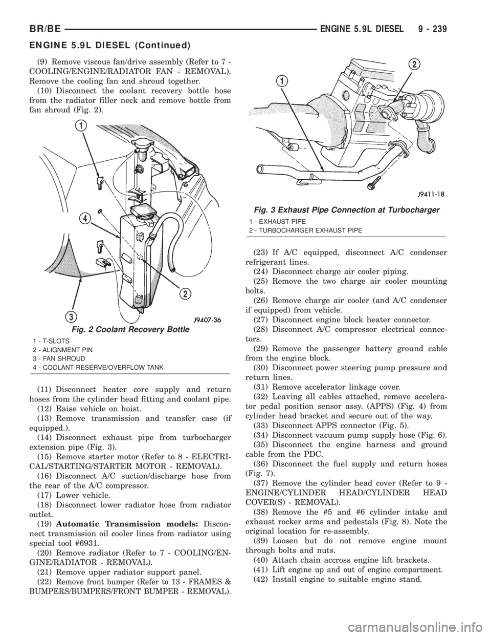
(10) Disconnect the coolant recovery bottle hose
from the radiator filler neck and remove bottle from
fan shroud (Fig. 2).
(11) Disconnect heater core supply and return
hoses from the cylinder head fitting and coolant pipe.
(12) Raise vehicle on hoist.
(13) Remove transmission and transfer case (if
equipped.).
(14) Disconnect exhaust pipe from turbocharger
extension pipe (Fig. 3).
(15) Remove starter motor (Refer to 8 - ELECTRI-
CAL/STARTING/STARTER MOTOR - REMOVAL).
(16) Disconnect A/C suction/discharge hose from
the rear of the A/C compressor.
(17) Lower vehicle.
(18) Disconnect lower radiator hose from radiator
outlet.
(19)Automatic Transmission models:Discon-
nect transmission oil cooler lines from radiator using
special tool #6931.
(20) Remove radiator (Refer to 7 - COOLING/EN-
GINE/RADIATOR - REMOVAL).
(21) Remove upper radiator support panel.
(22)
Remove front bumper (Refer to 13 - FRAMES &
BUMPERS/BUMPERS/FRONT BUMPER - REMOVAL).
(23) If A/C equipped, disconnect A/C condenser
refrigerant lines.
(24) Disconnect charge air cooler piping.
(25) Remove the two charge air cooler mounting
bolts.
(26) Remove charge air cooler (and A/C condenser
if equipped) from vehicle.
(27) Disconnect engine block heater connector.
(28) Disconnect A/C compressor electrical connec-
tors.
(29) Remove the passenger battery ground cable
from the engine block.
(30) Disconnect power steering pump pressure and
return lines.
(31) Remove accelerator linkage cover.
(32) Leaving all cables attached, remove accelera-
tor pedal position sensor assy. (APPS) (Fig. 4) from
cylinder head bracket and secure out of the way.
(33) Disconnect APPS connector (Fig. 5).
(34) Disconnect vacuum pump supply hose (Fig. 6).
(35) Disconnect the engine harness and ground
cable from the PDC.
(36) Disconnect the fuel supply and return hoses
(Fig. 7).
(37) Remove the cylinder head cover (Refer to 9 -
ENGINE/CYLINDER HEAD/CYLINDER HEAD
COVER(S) - REMOVAL).
(38) Remove the #5 and #6 cylinder intake and
exhaust rocker arms and pedestals (Fig. 8). Note the
original location for re-assembly.
(39) Loosen but do not remove engine mount
through bolts and nuts.
(40) Attach chain accross engine lift brackets.
(41)
Lift engine up and out of engine compartment.
(42) Install engine to suitable engine stand.
Fig. 2 Coolant Recovery Bottle
1 - T-SLOTS
2 - ALIGNMENT PIN
3 - FAN SHROUD
4 - COOLANT RESERVE/OVERFLOW TANK
Fig. 3 Exhaust Pipe Connection at Turbocharger
1 - EXHAUST PIPE
2 - TURBOCHARGER EXHAUST PIPE
BR/BEENGINE 5.9L DIESEL 9 - 239
ENGINE 5.9L DIESEL (Continued)
Page 1388 of 2889
REMOVALÐCRANKCASE BREATHER VAPOR
CANISTER
NOTE: It is recommended to empty the contents of
the vapor canister at each oil and filter service
interval.
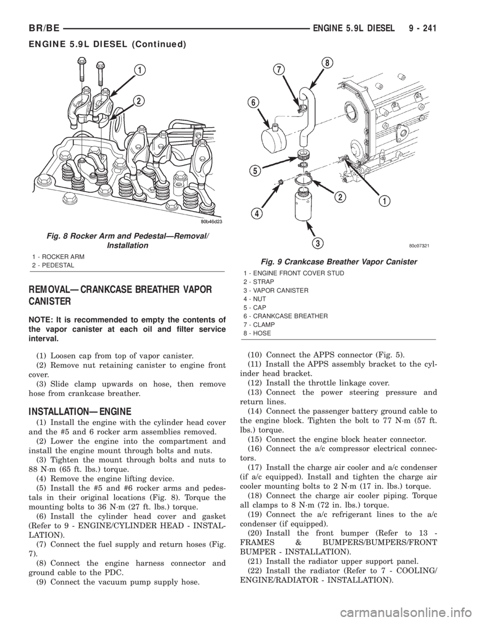
(1) Loosen cap from top of vapor canister.
(2) Remove nut retaining canister to engine front
cover.
(3) Slide clamp upwards on hose, then remove
hose from crankcase breather.
INSTALLATIONÐENGINE
(1) Install the engine with the cylinder head cover
and the #5 and 6 rocker arm assemblies removed.
(2) Lower the engine into the compartment and
install the engine mount through bolts and nuts.
(3) Tighten the mount through bolts and nuts to
88 N´m (65 ft. lbs.) torque.
(4) Remove the engine lifting device.
(5) Install the #5 and #6 rocker arms and pedes-
tals in their original locations (Fig. 8). Torque the
mounting bolts to 36 N´m (27 ft. lbs.) torque.
(6) Install the cylinder head cover and gasket
(Refer to 9 - ENGINE/CYLINDER HEAD - INSTAL-
LATION).
(7) Connect the fuel supply and return hoses (Fig.
7).
(8) Connect the engine harness connector and
ground cable to the PDC.
(9) Connect the vacuum pump supply hose.(10) Connect the APPS connector (Fig. 5).
(11) Install the APPS assembly bracket to the cyl-
inder head bracket.
(12) Install the throttle linkage cover.
(13) Connect the power steering pressure and
return lines.
(14) Connect the passenger battery ground cable to
the engine block. Tighten the bolt to 77 N´m (57 ft.
lbs.) torque.
(15) Connect the engine block heater connector.
(16) Connect the a/c compressor electrical connec-
tors.
(17) Install the charge air cooler and a/c condenser
(if a/c equipped). Install and tighten the charge air
cooler mounting bolts to 2 N´m (17 in. lbs.) torque.
(18) Connect the charge air cooler piping. Torque
all clamps to 8 N´m (72 in. lbs.) torque.
(19) Connect the a/c refrigerant lines to the a/c
condenser (if equipped).
(20) Install the front bumper (Refer to 13 -
FRAMES & BUMPERS/BUMPERS/FRONT
BUMPER - INSTALLATION).
(21) Install the radiator upper support panel.
(22) Install the radiator (Refer to 7 - COOLING/
ENGINE/RADIATOR - INSTALLATION).
Fig. 8 Rocker Arm and PedestalÐRemoval/
Installation
1 - ROCKER ARM
2 - PEDESTALFig. 9 Crankcase Breather Vapor Canister
1 - ENGINE FRONT COVER STUD
2 - STRAP
3 - VAPOR CANISTER
4 - NUT
5 - CAP
6 - CRANKCASE BREATHER
7 - CLAMP
8 - HOSE
BR/BEENGINE 5.9L DIESEL 9 - 241
ENGINE 5.9L DIESEL (Continued)
Page 1410 of 2889
Push Rods
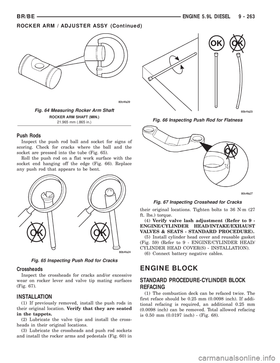
Inspect the push rod ball and socket for signs of
scoring. Check for cracks where the ball and the
socket are pressed into the tube (Fig. 65).
Roll the push rod on a flat work surface with the
socket end hanging off the edge (Fig. 66). Replace
any push rod that appears to be bent.
Crossheads
Inspect the crossheads for cracks and/or excessive
wear on rocker lever and valve tip mating surfaces
(Fig. 67).
INSTALLATION
(1) If previously removed, install the push rods in
their original location.Verify that they are seated
in the tappets.
(2) Lubricate the valve tips and install the cross-
heads in their original locations.
(3) Lubricate the crossheads and push rod sockets
and install the rocker arms and pedestals (Fig. 60) intheir original locations. Tighten bolts to 36 N´m (27
ft. lbs.) torque.
(4)Verify valve lash adjustment (Refer to 9 -
ENGINE/CYLINDER HEAD/INTAKE/EXHAUST
VALVES & SEATS - STANDARD PROCEDURE).
(5) Install cylinder head cover and reusable gasket
(Fig. 59) (Refer to 9 - ENGINE/CYLINDER HEAD/
CYLINDER HEAD COVER(S) - INSTALLATION).
(6) Connect battery negative cables.
ENGINE BLOCK
STANDARD PROCEDURE-CYLINDER BLOCK
REFACING
(1) The combustion deck can be refaced twice. The
first reface should be 0.25 mm (0.0098 inch). If addi-
tional refacing is required, an additional 0.25 mm
(0.0098 inch) can be removed. Total allowed refacing
is 0.50 mm (0.0197 inch) - (Fig. 68).
Fig. 64 Measuring Rocker Arm Shaft
ROCKER ARM SHAFT (MIN.)
21.965 mm (.865 in.)
Fig. 65 Inspecting Push Rod for Cracks
Fig. 66 Inspecting Push Rod for Flatness
Fig. 67 Inspecting Crosshead for Cracks
BR/BEENGINE 5.9L DIESEL 9 - 263
ROCKER ARM / ADJUSTER ASSY (Continued)
Page 1421 of 2889
(10)Verify valve lash adjustment (Refer to 9 -
ENGINE/CYLINDER HEAD/INTAKE/EXHAUST
VALVES & SEATS - STANDARD PROCEDURE).
(11)
Install the cylinder head cover and reusable gas-
ket (Fig. 85) (Refer to 9 - ENGINE/CYLINDER HEAD/
CYLINDER HEAD COVER(S) - INSTALLATION).
(12) Install gear housing cover (Refer to 9 -
ENGINE/VALVE TIMING/GEAR HOUSING COVER
- INSTALLATION).
(13) Install the crankshaft damper (Fig. 83) (Refer
to 9 - ENGINE/ENGINE BLOCK/VIBRATION
DAMPER - INSTALLATION).
(14) Install the fan support/hub assembly (Fig. 82)
and tighten bolts to 24 N´m (18 ft. lbs.) torque.
(15) Install the crankcase breather housing (Refer
to 9 - ENGINE - INSTALLATION).
(16) Install the charge air cooler (with a/c con-
denser and auxiliary transmission oil cooler, if
equipped) and tighten the mounting bolts to 2 N´m
(17 in. lbs.) torque.
(17) Connect charge air cooler inlet and outlet
pipes. Tighten clamps to 10 N´m (100 in. lbs.) torque.
(18) Install the radiator upper support panel.
(19) Close radiator petcock and lower the radiator
into the engine compartment. Tighten the mounting
bolts to 11 N´m (95 in. lbs.) torque.
(20) Raise vehicle on hoist.
(21)
Connect radiator lower hose and install clamp.
(22) Connect transmission auxiliary oil cooler lines
(if equipped).
(23) Lower vehicle.
(24) Install the fan shroud and tighten the mount-
ing screws to 6 N´m (50 in. lbs.) torque.(25) Install the viscous fan/drive assembly (Refer
to 7 - COOLING/ENGINE/RADIATOR FAN -
INSTALLATION).
(26) Install the coolant recovery and windshield
washer fluid reservoirs to the fan shroud.
(27) Connect the coolant recovery hose to the radi-
ator filler neck.
(28) Install the accessory drive belt (Refer to 7 -
COOLING/ACCESSORY DRIVE/DRIVE BELTS -
INSTALLATION).
(29) Install the front bumper assembly (Refer to 13
- FRAMES & BUMPERS/BUMPERS/FRONT
BUMPER - INSTALLATION).
(30) Add engine coolant (Refer to 7 - COOLING -
STANDARD PROCEDURE).
(31) Charge A/C system with refrigerant (if A/C
equipped) (Refer to 24 - HEATING & AIR CONDI-
TIONING/PLUMBING - STANDARD PROCEDURE).
(32) Connect the battery negative cables.
(33) Start engine and check for engine oil and cool-
ant leaks.
CONNECTING ROD BEARINGS
STANDARD PROCEDUREÐCONNECTING ROD
BEARING AND CRANKSHAFT JOURNAL
CLEARANCE
Measure the connecting rod bore with the bearings
installed and the bolts tightened to 100 N´m (73 ft.
lbs.) torque.
Record the smaller diameter.
Measure the diameter of the rod journal at the
location shown (Fig. 99). Calculate the average diam-
eter for each side of the journal.
The clearance is the difference between the con-
necting rod bore (smallest diameter) and the average
diameter for each side of the crankshaft journal.
CONNECTING ROD JOURNAL DIAMETER
LIMITS CHART
DESCRIPTION MEASUREMENT
CRANKSHAFT ROD
JOURNAL DIAMETERMINIMUM 68.962 mm
(2.715 in.)
MAXIMUM 69.013 mm
(2.717 in.)
OUT-OF-ROUND MAXIMUM 0.050 mm
(0.002 in.)
TAPER MAXIMUM 0.013 mm
(0.0005 in.)
BEARING CLEARANCE MAXIMUM 0.089 mm
(0.0035 in.)
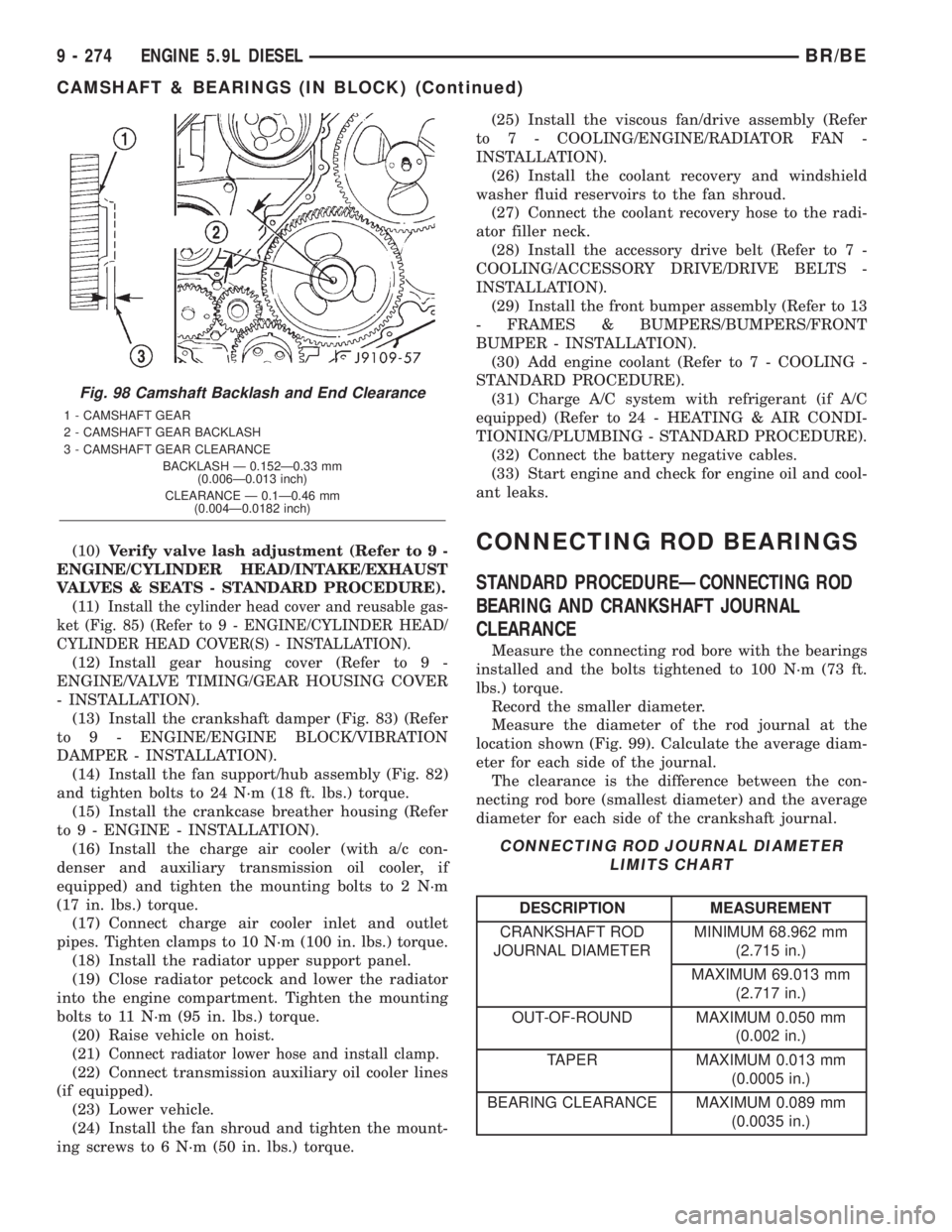
Fig. 98 Camshaft Backlash and End Clearance
1 - CAMSHAFT GEAR
2 - CAMSHAFT GEAR BACKLASH
3 - CAMSHAFT GEAR CLEARANCE
BACKLASH Ð 0.152Ð0.33 mm
(0.006Ð0.013 inch)
CLEARANCE Ð 0.1Ð0.46 mm
(0.004Ð0.0182 inch)
9 - 274 ENGINE 5.9L DIESELBR/BE
CAMSHAFT & BEARINGS (IN BLOCK) (Continued)
Page 1435 of 2889
(13) Install the suction tube and oil pan (Refer to 9
- ENGINE/LUBRICATION/OIL PAN - INSTALLA-
TION).
(14) Install the cylinder head onto the engine
(Refer to 9 - ENGINE/CYLINDER HEAD - INSTAL-
LATION).
(15) Install a new filter and fill the crankcase with
new engine oil.
(16) Connect the battery negative cables and start
engine.
PISTON RINGS
STANDARD PROCEDURE-PISTON RING
FITTING
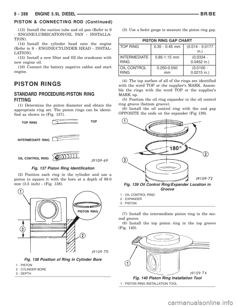
(1) Determine the piston diameter and obtain the
appropriate ring set. The piston rings can be identi-
fied as shown in (Fig. 137).
(2) Position each ring in the cylinder and use a
piston to square it with the bore at a depth of 89.0
mm (3.5 inch) - (Fig. 138).(3)
Use a feeler gauge to measure the piston ring gap.
PISTON RING GAP CHART
TOP RING 0.35 - 0.45 mm (0.014 - 0.0177
in.)
INTERMEDIATE
RING0.85-1.15 mm (0.0334 -
0.0452 in.)
OIL CONTROL
RING0.250-0.550
mm(0.0100 -
0.0215 in.)
(4) The top surface of all of the rings are identified
with the word TOP or the supplier's MARK. Assem-
ble the rings with the word TOP or the supplier's
MARK up.
(5) Position the oil ring expander in the oil control
ring groove (bottom groove).
(6) Install the oil control ring with the end gap
OPPOSITE the ends on the expander (Fig 139).
(7) Install the intermediate piston ring in the sec-
ond groove.
(8) Install the top piston ring in the top groove
(Fig. 140).
Fig. 137 Piston Ring Identification
Fig. 138 Position of Ring in Cylinder Bore
1 - PISTON
2 - CYLINDER BORE
3 - DEPTH
Fig. 139 Oil Control Ring/Expander Location in
Groove
1 - OIL CONTROL RING
2 - EXPANDER
3 - PISTON
Fig. 140 Piston Ring Installation Tool
1 - PISTON RING INSTALLATION TOOL
9 - 288 ENGINE 5.9L DIESELBR/BE
PISTON & CONNECTING ROD (Continued)
Page 1445 of 2889
INSTALLATION
(1) Install the plunger, spring, and plug as shown
in (Fig. 152). Tighten the plug to 80 N´m (60 ft. lbs.)
torque.
(2) Connect the battery negative cables.
(3) Start the engine and verify that it has oil pres-
sure.
OIL PRESSURE SENSOR/
SWITCH
DESCRIPTION
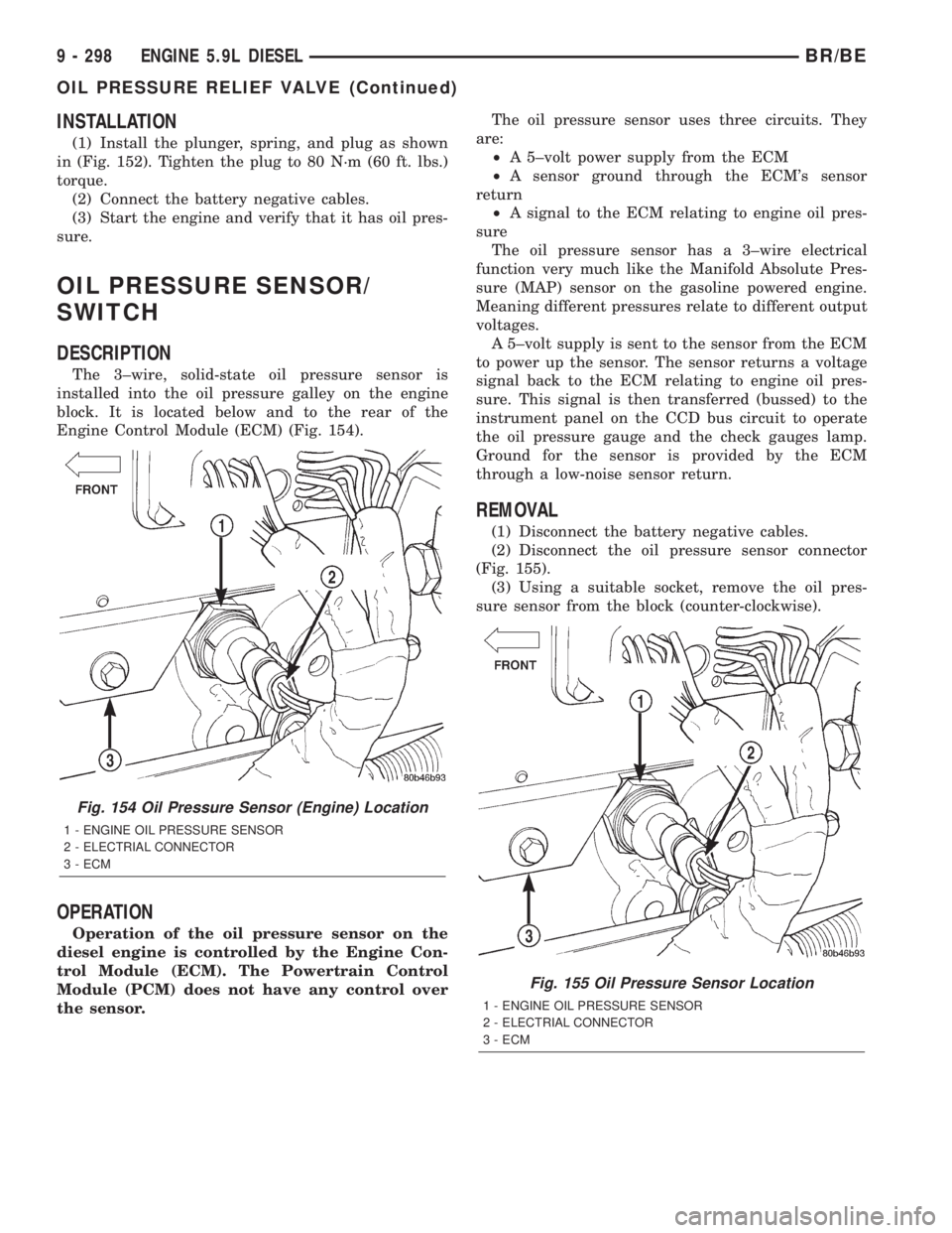
The 3±wire, solid-state oil pressure sensor is
installed into the oil pressure galley on the engine
block. It is located below and to the rear of the
Engine Control Module (ECM) (Fig. 154).
OPERATION
Operation of the oil pressure sensor on the
diesel engine is controlled by the Engine Con-
trol Module (ECM). The Powertrain Control
Module (PCM) does not have any control over
the sensor.The oil pressure sensor uses three circuits. They
are:
²A 5±volt power supply from the ECM
²A sensor ground through the ECM's sensor
return
²A signal to the ECM relating to engine oil pres-
sure
The oil pressure sensor has a 3±wire electrical
function very much like the Manifold Absolute Pres-
sure (MAP) sensor on the gasoline powered engine.
Meaning different pressures relate to different output
voltages.
A 5±volt supply is sent to the sensor from the ECM
to power up the sensor. The sensor returns a voltage
signal back to the ECM relating to engine oil pres-
sure. This signal is then transferred (bussed) to the
instrument panel on the CCD bus circuit to operate
the oil pressure gauge and the check gauges lamp.
Ground for the sensor is provided by the ECM
through a low-noise sensor return.
REMOVAL
(1) Disconnect the battery negative cables.
(2) Disconnect the oil pressure sensor connector
(Fig. 155).
(3) Using a suitable socket, remove the oil pres-
sure sensor from the block (counter-clockwise).
Fig. 154 Oil Pressure Sensor (Engine) Location
1 - ENGINE OIL PRESSURE SENSOR
2 - ELECTRIAL CONNECTOR
3 - ECM
Fig. 155 Oil Pressure Sensor Location
1 - ENGINE OIL PRESSURE SENSOR
2 - ELECTRIAL CONNECTOR
3 - ECM
9 - 298 ENGINE 5.9L DIESELBR/BE
OIL PRESSURE RELIEF VALVE (Continued)