2001 DODGE RAM battery location
[x] Cancel search: battery locationPage 723 of 2889
TESTING). If no VTSS problem is found, the follow-
ing procedure will help to locate a short or open in
the VTSS indicator control circuit. Refer to the
appropriate wiring information. The wiring informa-
tion includes wiring diagrams, proper wire and con-
nector repair procedures, details of wire harness
routing and retention, connector pin-out information
and location views for the various wire harness con-
nectors, splices and grounds.
WARNING: ON VEHICLES EQUIPPED WITH AIR-
BAGS, DISABLE THE AIRBAG SYSTEM BEFORE
ATTEMPTING ANY STEERING WHEEL, STEERING
COLUMN, OR INSTRUMENT PANEL COMPONENT
DIAGNOSIS OR SERVICE. DISCONNECT AND ISO-
LATE THE BATTERY NEGATIVE (GROUND) CABLE,
THEN WAIT TWO MINUTES FOR THE AIRBAG SYS-
TEM CAPACITOR TO DISCHARGE BEFORE PER-
FORMING FURTHER DIAGNOSIS OR SERVICE. THIS
IS THE ONLY SURE WAY TO DISABLE THE AIRBAG
SYSTEM. FAILURE TO TAKE THE PROPER PRE-
CAUTIONS COULD RESULT IN ACCIDENTAL AIR-
BAG DEPLOYMENT AND POSSIBLE PERSONAL
INJURY.
(1) Check the fused B(+) fuse (Fuse 12 - 10
ampere) in the Junction Block (JB). If OK, go to Step
2. If not OK, repair the shorted circuit or component
as required and replace the faulty fuse.
(2) Check for battery voltage at the fused B(+) fuse
(Fuse 12 - 10 ampere) in the JB. If OK, go to Step 3.
If not OK, repair the open fused B(+) circuit betweenthe JB and the Power Distribution Center (PDC) as
required.
(3) Disconnect and isolate the battery negative
cable. Disconnect the body wire harness connector for
the Compass Mini-Trip Computer (CMTC) from the
CMTC connector receptacle. Reconnect the battery
negative cable. Check for battery voltage at the fused
B(+) circuit cavity of the body wire harness connector
for the CMTC. If OK, go to Step 4. If not OK, repair
the open fused B(+) circuit between the CMTC indi-
cator and the JB as required.
(4) Disconnect and isolate the battery negative
cable. Disconnect the instrument panel wire harness
connector (Connector C2) for the Central Timer Mod-
ule (CTM) from the CTM connector receptacle. Check
for continuity between the VTSS indicator driver cir-
cuit cavity of the body wire harness connector for the
CMTC and a good ground. There should be no conti-
nuity. If OK, go to Step 5. If not OK, repair the
shorted VTSS indicator driver circuit between the
CMTC and the CTM as required.
(5) Check for continuity between the VTSS indica-
tor driver circuit cavities of the instrument panel
wire harness connector (Connector C2) for the CTM
and the body wire harness connector for the CMTC.
There should be continuity. If OK, replace the faulty
CMTC indicator. If not OK, repair the open VTSS
indicator driver circuit between the CMTC and the
CTM as required.
8Q - 4 VEHICLE THEFT SECURITYBR/BE
VTSS INDICATOR (Continued)
Page 725 of 2889
contains all of the switches for both the wiper and
washer systems.
²Washer Fluid Level Switch- The washer fluid
level switch is located in a dedicated hole on the
lower rear side of the washer reservoir, above the
washer pump/motor unit near the left front corner of
the engine compartment.
²Washer Nozzles- The dual fluidic washer noz-
zles are secured with integral snap features to dedi-
cated openings in the cowl plenum cover/grille panel
located near the base of the windshield. The washer
plumbing fittings for the washer nozzles are con-
cealed beneath the cowl plenum cover/grille panel.
²Washer Pump/Motor- The washer pump/mo-
tor unit is located in a dedicated hole on the lower
rear side of the washer reservoir near the left front
corner of the engine compartment.
²Washer Reservoir- The washer reservoir is
secured to the left side of the radiator fan shroud in
the left front corner of the engine compartment.
²Wiper Arms- The two wiper arms are secured
to the two wiper pivots, which extend through the
cowl plenum cover/grille panel located near the base
of the windshield.
²Wiper Blades- The two wiper blades are
secured to the two wiper arms, and are parked on
the glass near the bottom of the windshield when the
wiper system is not in operation.
²Wiper Module- The wiper pivots are the only
visible components of the wiper module. The remain-
der of the module is concealed within the cowl ple-
num beneath the cowl plenum cover/grille panel. The
wiper module includes the module bracket, the single
wiper motor, the wiper linkage, and the two wiper
pivots.
²Wiper Relay- The wiper relay is located in the
Power Distribution Center (PDC) in the engine com-
partment near the battery.
Features of the wiper and washer system include
the following:
²Continuous Wipe Modes- The two-speed
wiper motor and the internal circuitry of the multi-
function switch work in concert to provide two con-
tinuous wipe cycles, low speed or high speed.
²Intermittent Wipe Mode- The internal cir-
cuitry of the multi-function switch, the CTM, and the
wiper relay work in concert to provide an intermit-
tent wipe mode with multiple delay interval selec-
tions. On models with a high-line or premium CTM,
the CTM also automatically adjusts each manually
selected delay interval to compensate for vehicle
speed.
²Washer Mode- When the washer system is
activated with the multi-function switch while the
wiper system is operating, washer fluid will be dis-
pensed onto the windshield glass through the washernozzles for as long as the washer pump/motor is
energized.
²Wipe-After-Wash Mode- The internal circuitry
of the CTM provides a wipe-after-wash feature
which, if the wipers are turned Off, will operate the
washer pump/motor and the wipers for as long as the
washer system is activated, then provide several
additional wipe cycles after the washer system is
deactivated before parking the wiper blades near the
base of the windshield.
Hard wired circuitry connects the wiper and
washer system components to the electrical system of
the vehicle. These hard wired circuits are integral to
several wire harnesses, which are routed throughout
the vehicle and retained by many different methods.
These circuits may be connected to each other, to the
vehicle electrical system and to the wiper and washer
system components through the use of a combination
of soldered splices, splice block connectors, and many
different types of wire harness terminal connectors
and insulators. Refer to the appropriate wiring infor-
mation. The wiring information includes wiring dia-
grams, proper wire and connector repair procedures,
further details on wire harness routing and reten-
tion, as well as pin-out and location views for the
various wire harness connectors, splices and grounds.
OPERATION
The wiper and washer system is intended to pro-
vide the vehicle operator with a convenient, safe, and
reliable means of maintaining visibility through the
windshield glass. The various components of this sys-
tem are designed to convert electrical energy pro-
duced by the vehicle electrical system into the
mechanical action of the wiper blades to wipe the
outside surface of the glass, as well as into the
hydraulic action of the washer system to apply
washer fluid stored in an on-board reservoir to the
area of the glass to be wiped. When combined, these
components provide the means to effectively main-
tain clear visibility for the vehicle operator by remov-
ing excess accumulations of rain, snow, bugs, mud, or
other minor debris from the outside windshield glass
surface that might be encountered while driving the
vehicle under numerous types of inclement operating
conditions. The vehicle operator initiates all wiper
and washer system functions with the multi-function
switch control stalk that extends from the left side of
the steering column, just below the steering wheel.
Rotating the knob on the end of the multi-function
switch control stalk selects the desired wiper system
operating mode. The wiper system allows the vehicle
operator to select from two continuous wiper speeds,
Hi or Lo, or one of several intermittent wipe Delay
mode intervals. Pushing the button on the end of the
control stalk downwards towards the steering column
8R - 2 WIPERS/WASHERSBR/BE
WIPERS/WASHERS (Continued)
Page 726 of 2889
activates the washer pump/motor, which dispenses
washer fluid onto the windshield glass through the
washer nozzles.
When the ignition switch is in the Accessory or On
positions, battery current from a fuse in the Junction
Block (JB) is provided through a fused ignition
switch output (run-acc) circuit to the wiper motor
park switch, the wiper relay, and the multi-function
switch. The internal circuitry of the multi-function
switch provides a direct hard wired battery current
output to the low speed or high speed brushes of the
wiper motor when the Lo or Hi switch setting is
selected, which causes the wipers to cycle at the
selected speed. The intermittent wipe, and wipe-af-
ter-wash features of the wiper and washer system
are provided by the electronic intermittent wipe logic
circuit within the Central Timer Module (CTM). In
order to provide the intermittent wipe feature, the
CTM monitors the wiper switch state and the wiper
motor park switch state. In order to provide the
wipe-after-wash feature, the CTM monitors both the
washer switch state and the wiper motor park switch
state. When a Delay position is selected with the
multi-function switch control knob, the CTM logic cir-
cuit responds by calculating the correct delay inter-
val. The CTM then energizes the wiper relay by
pulling the relay control coil to ground. The ener-
gized wiper relay directs battery current through the
normally open contact of the relay back through the
internal circuitry of the multi-function switch to the
low speed brush of the wiper motor. The CTM moni-
tors the wiper motor operation through the wiper
park switch sense circuit, which allows the CTM to
determine the proper timing to begin the next wiper
blade sweep. The normal delay intervals are driver
adjustable from about one-half second to about eigh-
teen seconds.
The high-line and premium CTM also provides a
speed sensitive intermittent wipe feature. By moni-
toring vehicle speed messages received from the Pow-
ertrain Control Module (PCM) over the Chrysler
Collision Detection (CCD) data bus network, the
high-line or premium CTM is able to adjust the delay
intervals to compensate for vehicle speed. Above
about sixteen kilometers-per-hour (ten miles-per-
hour) the delay is driver adjustable from about one-
half second to about eighteen seconds. Below about
sixteen kilometers-per-hour (ten miles-per-hour) the
delay times are doubled by the CTM, from about one
second to about thirty-six seconds.
When the Off position of the multi-function switch
wiper control knob is selected, one of two events is
possible. The event that will occur depends upon the
position of the wiper blades on the windshield at the
moment that the Off position is selected. If the wiper
blades are in the down position on the windshieldwhen the Off position is selected, the park switch
that is integral to the wiper motor is closed to ground
and the wiper motor ceases to operate. If the wiper
blades are not in the down position on the windshield
at the moment the Off position is selected, the park
switch is closed to battery current through a fused
ignition switch output (run-acc) circuit. The park
switch sense circuit directs this battery current to
the low speed brush of the wiper motor through the
normally closed contact of the wiper relay and the
internal Off position circuitry of the multi-function
switch. This causes the wiper motor to continue run-
ning until the wiper blades are in the down position
on the windshield and the park switch is again
closed to ground.
When the Wash position of the multi-function
switch is selected, the Wash position circuitry within
the switch directs battery current to the washer
pump/motor. The CTM monitors the washer switch
state through a washer switch sense input. When the
washer switch is closed with the wiper system turned
Off, the CTM operates the wiper motor through the
wiper relay in the same manner as it does to provide
the Delay mode operation. After the state of the
washer switch changes to open, the CTM monitors
the wiper motor through the wiper park switch sense
circuit, which allows the CTM to monitor the number
of wiper blade sweeps.
Proper testing of the CTM, the PCM, or the CCD
data bus vehicle speed messages requires a DRBIIIt
scan tool. Refer to the appropriate diagnostic infor-
mation. Refer to the owner's manual in the vehicle
glove box for more information on the features and
operation of the wiper and washer system.
DIAGNOSIS AND TESTING - WIPER &
WASHER SYSTEM
WIPER SYSTEM
The diagnosis found here addresses an electrically
inoperative wiper system. If the wiper motor oper-
ates, but the wipers do not move on the windshield,
replace the faulty wiper module. If the wipers oper-
ate, but chatter, lift, or do not clear the glass, clean
and inspect the wiper system components as
required. (Refer to 8 - ELECTRICAL/WIPERS/
WASHERS - INSPECTION) and (Refer to 8 - ELEC-
TRICAL/WIPERS/WASHERS - CLEANING). Refer to
the appropriate wiring information. The wiring infor-
mation includes wiring diagrams, proper wire and
connector repair procedures, details of wire harness
routing and retention, connector pin-out information
and location views for the various wire harness con-
nectors, splices and grounds.
The following tests will help to diagnose the hard
wired components and circuits of the wiper system.
BR/BEWIPERS/WASHERS 8R - 3
WIPERS/WASHERS (Continued)
Page 728 of 2889
(10) Disconnect the headlamp and dash wire har-
ness connector for the wiper module from the wiper
motor pigtail wire connector. Reconnect the battery
negative cable. Turn the ignition switch to the On
position. Place the multi-function switch in the posi-
tions indicated in the tests below, and check for bat-
tery voltage at the appropriate cavity of the
headlamp and dash wire harness connector for the
wiper motor.
(a) Check for battery voltage at the fused igni-
tion switch output (run-acc) circuit cavity of the
headlamp and dash wire harness connector for the
wiper module with the multi-function switch in
any position. If OK, go to Step b. If not OK, repair
the open fused ignition switch output (run-acc) cir-
cuit between the wiper module and the JB as
required.
(b) Check for battery voltage at the wiper switch
low speed output circuit cavity of the headlamp
and dash wire harness connector for the wiper
module with the multi-function switch in the Lo
position. If OK, go to Step c. If not OK, repair the
open wiper switch low speed output circuit between
the wiper module and the multi-function switch as
required.
(c) Check for battery voltage at the wiper switch
high speed output circuit cavity of the headlamp
and dash wire harness connector for the wiper
module with the multi-function switch in the Hi
position. If OK, go to Step d. If not OK, repair the
open wiper switch high speed output circuit
between the wiper module and the multi-function
switch as required.
(d) Check for battery voltage at the wiper park
switch sense circuit cavity of the headlamp and
dash wire harness connector for the wiper module
with the multi-function switch in the Lo or Hi posi-
tion, then move the switch to the Off position. The
meter should switch between battery voltage and
zero volts while the wipers are cycling. The meter
should read battery voltage when the switch is
first moved to the Off position until the wipers
park, and then read a steady zero volts. If not OK,
replace the faulty wiper module.
WASHER SYSTEM
The diagnosis found here addresses an electrically
inoperative washer system. If the washer pump/mo-
tor operates, but no washer fluid is emitted from the
washer nozzles, be certain to check the fluid level in
the reservoir. Also inspect the washer system compo-
nents as required. (Refer to 8 - ELECTRICAL/WIP-
ERS/WASHERS - INSPECTION). Refer to the
appropriate wiring information. The wiring informa-
tion includes wiring diagrams, proper wire and con-
nector repair procedures, details of wire harnessrouting and retention, connector pin-out information
and location views for the various wire harness con-
nectors, splices and grounds.
WARNING: ON VEHICLES EQUIPPED WITH AIR-
BAGS, DISABLE THE AIRBAG SYSTEM BEFORE
ATTEMPTING ANY STEERING WHEEL, STEERING
COLUMN, OR INSTRUMENT PANEL COMPONENT
DIAGNOSIS OR SERVICE. DISCONNECT AND ISO-
LATE THE BATTERY NEGATIVE (GROUND) CABLE,
THEN WAIT TWO MINUTES FOR THE AIRBAG SYS-
TEM CAPACITOR TO DISCHARGE BEFORE PER-
FORMING FURTHER DIAGNOSIS OR SERVICE. THIS
IS THE ONLY SURE WAY TO DISABLE THE AIRBAG
SYSTEM. FAILURE TO TAKE THE PROPER PRE-
CAUTIONS COULD RESULT IN ACCIDENTAL AIR-
BAG DEPLOYMENT AND POSSIBLE PERSONAL
INJURY.
(1) Turn the ignition switch to the On position.
Turn the multi-function switch wiper control knob to
the Lo or Hi speed position. Check whether the wip-
ers operate. If OK, go to Step 2. If not OK, repair the
wiper system as required before proceeding with the
following tests. Refer to WIPER SYSTEM .
(2) Turn the multi-function switch wiper control
knob to the Off position. Depress the washer button.
The washer pump should operate and the wipers
should operate for as long as the washer button is
depressed. The wipers should continue to operate for
about three sweep cycles after the button is released
before they park. If the wipers are OK, but the wash-
ers are not, go to Step 3. If the washers are OK, but
the wipers are not, go to Step 5.
(3) Turn the ignition switch to the Off position.
Disconnect and isolate the battery negative cable.
Disconnect the headlamp and dash wire harness con-
nector for the washer pump/motor from the motor
connector receptacle. Measure the resistance between
the ground circuit cavity of the headlamp and dash
wire harness connector for the washer pump/motor
and a good ground. The meter should read zero
ohms. If OK, go to Step 4. If not OK, repair the open
ground circuit to ground (G100) as required.
(4) Reconnect the battery negative cable. Turn the
ignition switch to the On position. With the washer
button depressed, check for battery voltage at the
washer switch output circuit cavity of the headlamp
and dash wire harness connector for the washer
pump/motor. If OK, replace the faulty washer pump/
motor. If not OK, repair the open washer switch out-
put circuit between the washer pump/motor and the
multi-function switch as required.
(5) Turn the ignition switch to the Off position.
Disconnect and isolate the battery negative cable.
Disconnect the instrument panel wire harness con-
nector (Connector C1) for the Central Timer Module
BR/BEWIPERS/WASHERS 8R - 5
WIPERS/WASHERS (Continued)
Page 733 of 2889
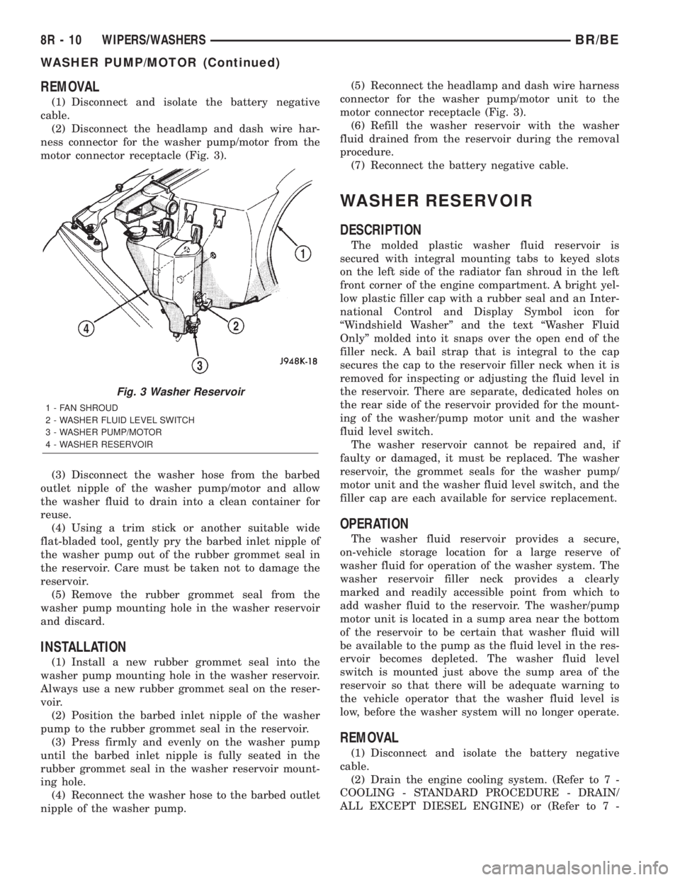
REMOVAL
(1) Disconnect and isolate the battery negative
cable.
(2) Disconnect the headlamp and dash wire har-
ness connector for the washer pump/motor from the
motor connector receptacle (Fig. 3).
(3) Disconnect the washer hose from the barbed
outlet nipple of the washer pump/motor and allow
the washer fluid to drain into a clean container for
reuse.
(4) Using a trim stick or another suitable wide
flat-bladed tool, gently pry the barbed inlet nipple of
the washer pump out of the rubber grommet seal in
the reservoir. Care must be taken not to damage the
reservoir.
(5) Remove the rubber grommet seal from the
washer pump mounting hole in the washer reservoir
and discard.
INSTALLATION
(1) Install a new rubber grommet seal into the
washer pump mounting hole in the washer reservoir.
Always use a new rubber grommet seal on the reser-
voir.
(2) Position the barbed inlet nipple of the washer
pump to the rubber grommet seal in the reservoir.
(3) Press firmly and evenly on the washer pump
until the barbed inlet nipple is fully seated in the
rubber grommet seal in the washer reservoir mount-
ing hole.
(4) Reconnect the washer hose to the barbed outlet
nipple of the washer pump.(5) Reconnect the headlamp and dash wire harness
connector for the washer pump/motor unit to the
motor connector receptacle (Fig. 3).
(6) Refill the washer reservoir with the washer
fluid drained from the reservoir during the removal
procedure.
(7) Reconnect the battery negative cable.
WASHER RESERVOIR
DESCRIPTION
The molded plastic washer fluid reservoir is
secured with integral mounting tabs to keyed slots
on the left side of the radiator fan shroud in the left
front corner of the engine compartment. A bright yel-
low plastic filler cap with a rubber seal and an Inter-
national Control and Display Symbol icon for
ªWindshield Washerº and the text ªWasher Fluid
Onlyº molded into it snaps over the open end of the
filler neck. A bail strap that is integral to the cap
secures the cap to the reservoir filler neck when it is
removed for inspecting or adjusting the fluid level in
the reservoir. There are separate, dedicated holes on
the rear side of the reservoir provided for the mount-
ing of the washer/pump motor unit and the washer
fluid level switch.
The washer reservoir cannot be repaired and, if
faulty or damaged, it must be replaced. The washer
reservoir, the grommet seals for the washer pump/
motor unit and the washer fluid level switch, and the
filler cap are each available for service replacement.
OPERATION
The washer fluid reservoir provides a secure,
on-vehicle storage location for a large reserve of
washer fluid for operation of the washer system. The
washer reservoir filler neck provides a clearly
marked and readily accessible point from which to
add washer fluid to the reservoir. The washer/pump
motor unit is located in a sump area near the bottom
of the reservoir to be certain that washer fluid will
be available to the pump as the fluid level in the res-
ervoir becomes depleted. The washer fluid level
switch is mounted just above the sump area of the
reservoir so that there will be adequate warning to
the vehicle operator that the washer fluid level is
low, before the washer system will no longer operate.
REMOVAL
(1) Disconnect and isolate the battery negative
cable.
(2) Drain the engine cooling system. (Refer to 7 -
COOLING - STANDARD PROCEDURE - DRAIN/
ALL EXCEPT DIESEL ENGINE) or (Refer to 7 -
Fig. 3 Washer Reservoir
1 - FAN SHROUD
2 - WASHER FLUID LEVEL SWITCH
3 - WASHER PUMP/MOTOR
4 - WASHER RESERVOIR
8R - 10 WIPERS/WASHERSBR/BE
WASHER PUMP/MOTOR (Continued)
Page 738 of 2889
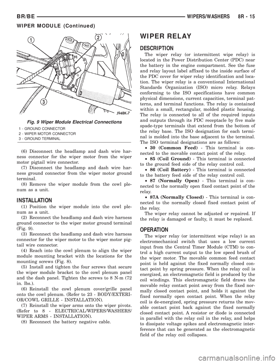
(6) Disconnect the headlamp and dash wire har-
ness connector for the wiper motor from the wiper
motor pigtail wire connector.
(7) Disconnect the headlamp and dash wire har-
ness ground connector from the wiper motor ground
terminal.
(8) Remove the wiper module from the cowl ple-
num as a unit.
INSTALLATION
(1) Position the wiper module into the cowl ple-
num as a unit.
(2) Reconnect the headlamp and dash wire harness
ground connector to the wiper motor ground terminal
(Fig. 9).
(3) Reconnect the headlamp and dash wire harness
connector for the wiper motor to the wiper motor pig-
tail wire connector.
(4) Reach into the cowl plenum to align the wiper
module mounting bracket with the locations for the
mounting screws (Fig. 8).
(5) Install and tighten the four screws that secure
the wiper module bracket to the cowl plenum panel
and the dash panel. Tighten the screws to 8 N´m (72
in. lbs.).
(6) Reinstall the cowl plenum cover/grille panel
onto the cowl plenum. (Refer to 23 - BODY/EXTERI-
OR/COWL GRILLE - INSTALLATION).
(7) Reinstall the wiper arms onto the wiper pivots.
(Refer to 8 - ELECTRICAL/WIPERS/WASHERS/
WIPER ARMS - INSTALLATION).
(8) Reconnect the battery negative cable.
WIPER RELAY
DESCRIPTION
The wiper relay (or intermittent wipe relay) is
located in the Power Distribution Center (PDC) near
the battery in the engine compartment. See the fuse
and relay layout label affixed to the inside surface of
the PDC cover for wiper relay identification and loca-
tion. The wiper relay is a conventional International
Standards Organization (ISO) micro relay. Relays
conforming to the ISO specifications have common
physical dimensions, current capacities, terminal pat-
terns, and terminal functions. The relay is contained
within a small, rectangular, molded plastic housing.
The relay is connected to all of the required inputs
and outputs through its PDC receptacle by five male
spade-type terminals that extend from the bottom of
the relay base. The ISO designation for each termi-
nal is molded into the base adjacent to the terminal.
The ISO terminal designations are as follows:
²30 (Common Feed)- This terminal is con-
nected to the movable contact point of the relay.
²85 (Coil Ground)- This terminal is connected
to the ground feed side of the relay control coil.
²86 (Coil Battery)- This terminal is connected
to the battery feed side of the relay control coil.
²87 (Normally Open)- This terminal is con-
nected to the normally open fixed contact point of the
relay.
²87A (Normally Closed)- This terminal is con-
nected to the normally closed fixed contact point of
the relay.
The wiper relay cannot be adjusted or repaired. If
the relay is damaged or faulty, it must be replaced.
OPERATION
The wiper relay (or intermittent wipe relay) is an
electromechanical switch that uses a low current
input from the Central Timer Module (CTM) to con-
trol a high current output to the low speed brush of
the wiper motor. The movable common feed contact
point is held against the fixed normally closed con-
tact point by spring pressure. When the relay coil is
energized, an electromagnetic field is produced by the
coil windings. This electromagnetic field draws the
movable relay contact point away from the fixed nor-
mally closed contact point, and holds it against the
fixed normally open contact point. When the relay
coil is de-energized, spring pressure returns the mov-
able contact point back against the fixed normally
closed contact point. A resistor or diode is connected
in parallel with the relay coil in the relay, and helps
to dissipate voltage spikes and electromagnetic inter-
ference that can be generated as the electromagnetic
field of the relay coil collapses.
Fig. 9 Wiper Module Electrical Connections
1 - GROUND CONNECTOR
2 - WIPER MOTOR CONNECTOR
3 - GROUND TERMINAL
BR/BEWIPERS/WASHERS 8R - 15
WIPER MODULE (Continued)
Page 739 of 2889
The wiper relay terminals are connected to the
vehicle electrical system through a connector recepta-
cle in the Power Distribution Center (PDC). The
inputs and outputs of the wiper relay include:
²The common feed terminal (30) is connected to
the wiper motor low speed brush through the wiper
control circuitry of the multi-function switch on the
steering column. When the wiper relay is de-ener-
gized, the common feed terminal is connected to the
wiper park switch output through the wiper park
switch sense circuit. The wiper park switch output
may be battery current (wipers are not parked), or
ground (wipers are parked). When the wiper relay is
energized, the common feed terminal of the wiper is
connected to battery current from a fuse in the Junc-
tion Block (JB) through a fused ignition switch out-
put (run-acc) circuit.
²The coil ground terminal (85) is connected to the
relay control output of the CTM through the wiper
motor relay control circuit. The CTM controls the
ground path for this circuit internally to energize or
de-energize the wiper relay based upon its program-
ming and inputs from the wiper and washer control
circuitry of the multi-function switch and from the
wiper motor park switch.
²The coil battery terminal (86) is connected to
battery current from a fuse in the Junction Block
(JB) through a fused ignition switch output (run-acc)
circuit whenever the ignition switch is in the On or
Accessory positions.
²The normally open terminal (87) is connected to
battery current from a fuse in the Junction Block
(JB) through a fused ignition switch output (run-acc)
circuit whenever the wiper relay control coil is ener-
gized by the CTM. This circuit provides fused igni-
tion switch output (run-acc) current to the wiper
motor low speed brush only when the wiper relay
control coil is energized.
²The normally closed terminal (87A) is connected
to the output of the wiper motor park switch through
the wiper motor park switch sense circuit. This cir-
cuit provides battery current (wipers are not parked)
or ground (wipers are parked) to the wiper motor low
speed brush whenever the wiper relay control coil is
de-energized and the Off position of the wiper control
of the multi-function switch is selected.
The wiper relay can be diagnosed using conven-
tional diagnostic tools and methods.
DIAGNOSIS AND TESTING - WIPER RELAY
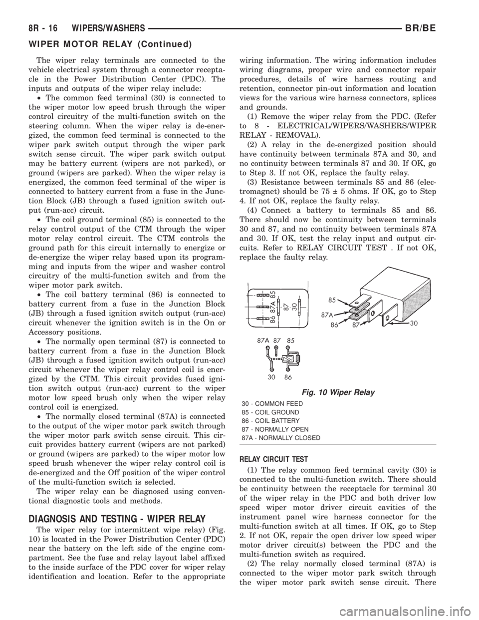
The wiper relay (or intermittent wipe relay) (Fig.
10) is located in the Power Distribution Center (PDC)
near the battery on the left side of the engine com-
partment. See the fuse and relay layout label affixed
to the inside surface of the PDC cover for wiper relay
identification and location. Refer to the appropriatewiring information. The wiring information includes
wiring diagrams, proper wire and connector repair
procedures, details of wire harness routing and
retention, connector pin-out information and location
views for the various wire harness connectors, splices
and grounds.
(1) Remove the wiper relay from the PDC. (Refer
to 8 - ELECTRICAL/WIPERS/WASHERS/WIPER
RELAY - REMOVAL).
(2) A relay in the de-energized position should
have continuity between terminals 87A and 30, and
no continuity between terminals 87 and 30. If OK, go
to Step 3. If not OK, replace the faulty relay.
(3) Resistance between terminals 85 and 86 (elec-
tromagnet) should be 75 5 ohms. If OK, go to Step
4. If not OK, replace the faulty relay.
(4) Connect a battery to terminals 85 and 86.
There should now be continuity between terminals
30 and 87, and no continuity between terminals 87A
and 30. If OK, test the relay input and output cir-
cuits. Refer to RELAY CIRCUIT TEST . If not OK,
replace the faulty relay.
RELAY CIRCUIT TEST
(1) The relay common feed terminal cavity (30) is
connected to the multi-function switch. There should
be continuity between the receptacle for terminal 30
of the wiper relay in the PDC and both driver low
speed wiper motor driver circuit cavities of the
instrument panel wire harness connector for the
multi-function switch at all times. If OK, go to Step
2. If not OK, repair the open driver low speed wiper
motor driver circuit(s) between the PDC and the
multi-function switch as required.
(2) The relay normally closed terminal (87A) is
connected to the wiper motor park switch through
the wiper motor park switch sense circuit. There
Fig. 10 Wiper Relay
30 - COMMON FEED
85 - COIL GROUND
86 - COIL BATTERY
87 - NORMALLY OPEN
87A - NORMALLY CLOSED
8R - 16 WIPERS/WASHERSBR/BE
WIPER MOTOR RELAY (Continued)
Page 740 of 2889
should be continuity between the receptacle for ter-
minal 87A of the wiper relay in the PDC and the
wiper motor park switch sense circuit cavity of the
headlamp and dash wire harness connector for the
wiper motor at all times. If OK, go to Step 3. If not
OK, repair the open wiper motor park switch sense
circuit between the PDC and the wiper motor as
required.
(3) The relay normally open terminal (87) is con-
nected to a fused ignition switch output (run-acc)
fuse in the Junction Block (JB) through a fused igni-
tion switch output (run-acc) circuit. There should be
battery voltage at the receptacle for terminal 87 of
the wiper relay in the PDC whenever the ignition
switch is in the On or Accessory positions. If OK, go
to Step 4. If not OK, repair the open fused ignition
switch output (run-acc) circuit between the PDC and
the JB as required.
(4) The coil battery terminal (86) is connected to a
fused ignition switch output (run-acc) fuse in the JB
through a fused ignition switch output (run-acc) cir-
cuit. There should be battery voltage at the recepta-
cle for terminal 86 of the wiper relay in the PDC
whenever the ignition switch is in the On or Acces-
sory positions. If OK, go to Step 5. If not OK, repair
the open fused ignition switch output (run-acc) cir-
cuit between the PDC and the JB as required.
(5) The coil ground terminal (85) is connected to
the output of the Central Timer Module (CTM)
through the wiper motor relay control circuit. There
should be continuity between the receptacle for ter-
minal 85 of the wiper relay in the PDC and the wiper
motor relay control circuit cavity of the instrument
panel wire harness connector (Connector C1) for the
CTM at all times. If not OK, repair the open wiper
motor relay control circuit between the PDC and the
CTM as required.
REMOVAL
(1) Disconnect and isolate the battery negative
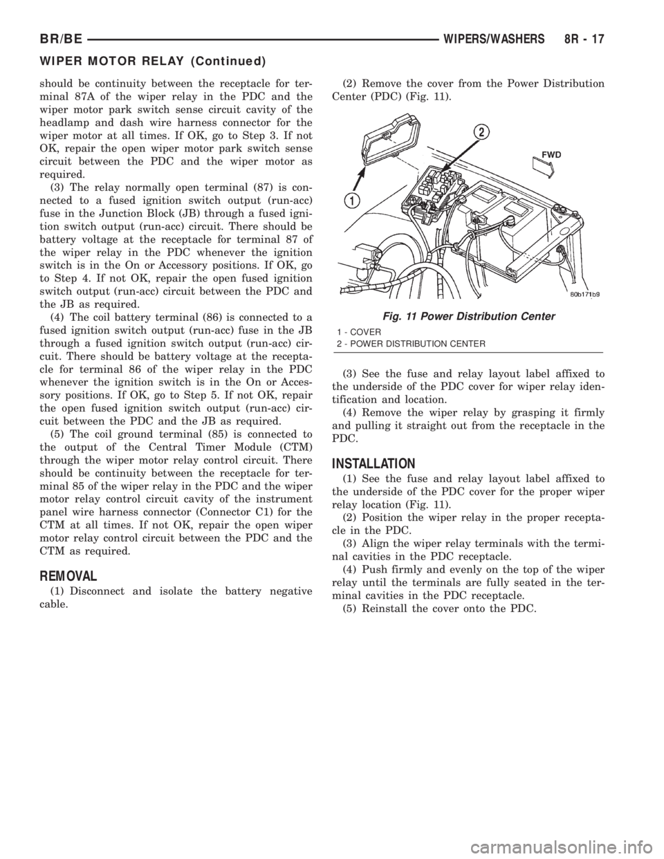
cable.(2) Remove the cover from the Power Distribution
Center (PDC) (Fig. 11).
(3) See the fuse and relay layout label affixed to
the underside of the PDC cover for wiper relay iden-
tification and location.
(4) Remove the wiper relay by grasping it firmly
and pulling it straight out from the receptacle in the
PDC.
INSTALLATION
(1) See the fuse and relay layout label affixed to
the underside of the PDC cover for the proper wiper
relay location (Fig. 11).
(2) Position the wiper relay in the proper recepta-
cle in the PDC.
(3) Align the wiper relay terminals with the termi-
nal cavities in the PDC receptacle.
(4) Push firmly and evenly on the top of the wiper
relay until the terminals are fully seated in the ter-
minal cavities in the PDC receptacle.
(5) Reinstall the cover onto the PDC.
Fig. 11 Power Distribution Center
1 - COVER
2 - POWER DISTRIBUTION CENTER
BR/BEWIPERS/WASHERS 8R - 17
WIPER MOTOR RELAY (Continued)