2001 DODGE RAM battery location
[x] Cancel search: battery locationPage 1143 of 2889
which replace all in-line fusible links. The PDC also
houses up to thirteen blade-type fuses (two standard-
type and eleven mini-type), up to seventeen Interna-
tional Standards Organization (ISO) relays (five
standard-type and twelve micro-type), two joint con-
nectors (one eighteen-way and one twenty-eight-way),
a forty-three-way engine wire harness in-line connec-
tor and a fuse puller.
The PDC housing is secured in the engine compart-
ment on the outboard side with two screws to the left
front inner fender shield, and with a screw on the
inboard side to the left front inner wheel house. The
PDC housing has a molded plastic cover that
includes two integral latches, one on each side. The
PDC cover is easily opened and removed for service
access and has a convenient adhesive-backed fuse
and relay layout map affixed to the inside surface of
the cover to ensure proper component identification.
The PDC unit cannot be repaired and is only ser-
viced as a unit with the headlamp and dash wire
harness. If the internal circuits or the PDC housing
are faulty or damaged, the headlamp and dash wire
harness unit must be replaced.
OPERATION
All of the current from the battery and the gener-
ator output enters the PDC through two cables with
eyelets that are secured with nuts to the two B(+)
terminal studs located just inside the inboard end of
the PDC housing. The PDC cover is unlatched and
removed to access the battery and generator output
connection B(+) terminal studs, the fuses, the relays,
the joint connectors and the engine wire harness in-
line connector. Internal connection of all of the PDC
circuits is accomplished by an intricate combination
of hard wiring and bus bars. Refer toPower Distri-
butionin the index of this service manual for the
location of complete PDC circuit diagrams.
REMOVAL
The Power Distribution Center (PDC) is serviced
as a unit with the headlamp and dash wire harness.
If any internal circuit of the PDC or the PDC hous-
ing is faulty or damaged, the entire PDC and head-
lamp and dash wire harness unit must be replaced.
(1) Disconnect and isolate the battery negative
cable.
(2) Disconnect each of the headlamp and dash wire
harness connectors. Refer toConnector Locations
in the index of this service manual for the location of
more information on the headlamp and dash wire
harness connector locations.
(3) Remove all of the fasteners that secure each of
the headlamp and dash wire harness ground eyelets
to the vehicle body and chassis components. Refer to
Connector Locationsin the index of this servicemanual for the location of more information on the
ground eyelet locations.
(4) Disengage each of the retainers that secure the
headlamp and dash wire harness to the vehicle body
and chassis components. Refer toConnector Loca-
tionsin the index of this service manual for the loca-
tion of more information on the headlamp and dash
wire harness retainer locations.
(5) Unlatch and remove the cover from the PDC.
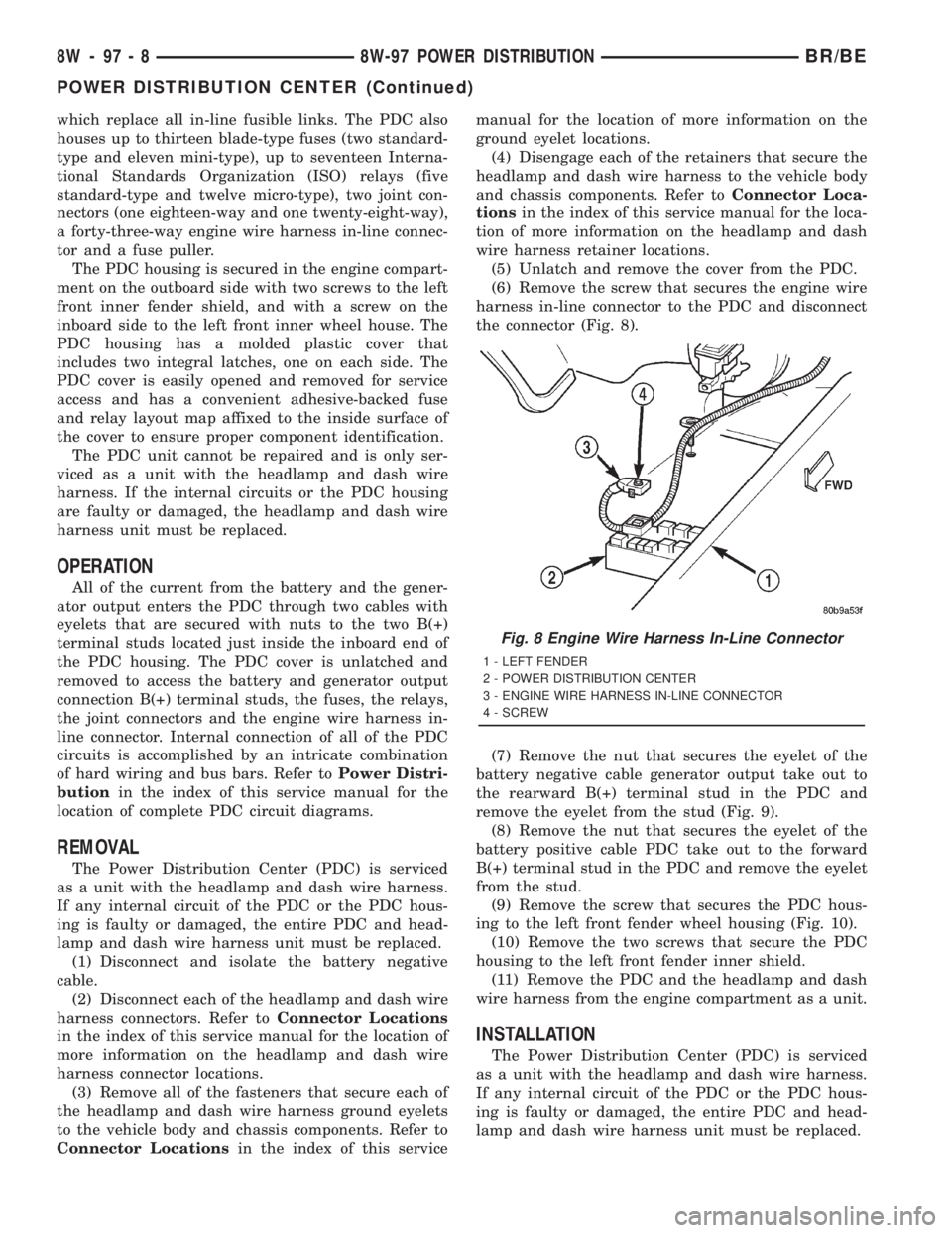
(6) Remove the screw that secures the engine wire
harness in-line connector to the PDC and disconnect
the connector (Fig. 8).
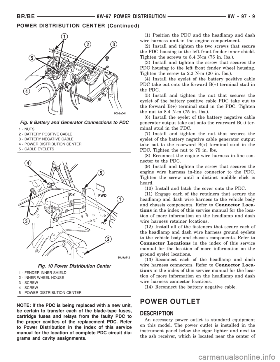
(7) Remove the nut that secures the eyelet of the
battery negative cable generator output take out to
the rearward B(+) terminal stud in the PDC and
remove the eyelet from the stud (Fig. 9).
(8) Remove the nut that secures the eyelet of the
battery positive cable PDC take out to the forward
B(+) terminal stud in the PDC and remove the eyelet
from the stud.
(9) Remove the screw that secures the PDC hous-
ing to the left front fender wheel housing (Fig. 10).
(10) Remove the two screws that secure the PDC
housing to the left front fender inner shield.
(11) Remove the PDC and the headlamp and dash
wire harness from the engine compartment as a unit.
INSTALLATION
The Power Distribution Center (PDC) is serviced
as a unit with the headlamp and dash wire harness.
If any internal circuit of the PDC or the PDC hous-
ing is faulty or damaged, the entire PDC and head-
lamp and dash wire harness unit must be replaced.
Fig. 8 Engine Wire Harness In-Line Connector
1 - LEFT FENDER
2 - POWER DISTRIBUTION CENTER
3 - ENGINE WIRE HARNESS IN-LINE CONNECTOR
4 - SCREW
8W - 97 - 8 8W-97 POWER DISTRIBUTIONBR/BE
POWER DISTRIBUTION CENTER (Continued)
Page 1144 of 2889
NOTE: If the PDC is being replaced with a new unit,
be certain to transfer each of the blade-type fuses,
cartridge fuses and relays from the faulty PDC to
the proper cavities of the replacement PDC. Refer
to Power Distribution in the index of this service
manual for the location of complete PDC circuit dia-
grams and cavity assignments.(1) Position the PDC and the headlamp and dash
wire harness unit in the engine compartment.
(2) Install and tighten the two screws that secure
the PDC housing to the left front fender inner shield.
Tighten the screws to 8.4 N´m (75 in. lbs.).
(3) Install and tighten the screw that secures the
PDC housing to the left front fender wheel housing.
Tighten the screw to 2.2 N´m (20 in. lbs.).
(4) Install the eyelet of the battery positive cable
PDC take out onto the forward B(+) terminal stud in
the PDC.
(5) Install and tighten the nut that secures the
eyelet of the battery positive cable PDC take out to
the forward B(+) terminal stud in the PDC. Tighten
the nut to 8.4 N´m (75 in. lbs.).
(6) Install the eyelet of the battery negative cable
generator output take out onto the rearward B(+) ter-
minal stud in the PDC.
(7) Install and tighten the nut that secures the
eyelet of the battery negative cable generator output
take out to the rearward B(+) terminal stud in the
PDC. Tighten the nut to 75 in. lbs.
(8) Reconnect the engine wire harness in-line con-
nector to the PDC.
(9) Install and tighten the screw that secures the
engine wire harness in-line connector to the PDC.
Tighten the screw until a distinct audible click is
heard.
(10) Install and latch the cover onto the PDC.
(11) Engage each of the retainers that secure the
headlamp and dash wire harness to the vehicle body
and chassis components. Refer toConnector Loca-
tionsin the index of this service manual for the loca-
tion of more information on the headlamp and dash
wire harness retainer locations.
(12) Install all of the fasteners that secure each of
the headlamp and dash wire harness ground eyelets
to the vehicle body and chassis components. Refer to
Connector Locationsin the index of this service
manual for the location of more information on the
ground eyelet locations.
(13) Reconnect each of the headlamp and dash
wire harness connectors. Refer toConnector Loca-
tionsin the index of this service manual for the loca-
tion of more information on the headlamp and dash
wire harness connector locations.
(14) Reconnect the battery negative cable.POWER OUTLET
DESCRIPTION
An accessory power outlet is standard equipment
on this model. The power outlet is installed in the
instrument panel below the cigar lighter and next to
the ash receiver, which is located near the center of
Fig. 9 Battery and Generator Connections to PDC
1 - NUTS
2 - BATTERY POSITIVE CABLE
3 - BATTERY NEGATIVE CABLE
4 - POWER DISTRIBUTION CENTER
5 - CABLE EYELETS
Fig. 10 Power Distribution Center
1 - FENDER INNER SHIELD
2 - INNER WHEEL HOUSE
3 - SCREW
4 - SCREW
5 - POWER DISTRIBUTION CENTER
BR/BE8W-97 POWER DISTRIBUTION 8W - 97 - 9
POWER DISTRIBUTION CENTER (Continued)
Page 1158 of 2889
(4) A controlled hone motor speed between 200 and
300 RPM is necessary to obtain the proper cross-
hatch angle. The number of up and down strokes per
minute can be regulated to get the desired 50É to 60É
angle. Faster up and down strokes increase the cross-
hatch angle.
(5) After honing, it is necessary that the block be
cleaned to remove all traces of abrasive. Use a brush
to wash parts with a solution of hot water and deter-
gent. Dry parts thoroughly. Use a clean, white, lint-
free cloth to check that the bore is clean. Oil the
bores after cleaning to prevent rusting.
STANDARD PROCEDUREÐHYDROSTATIC
LOCK
CAUTION: DO NOT use the starter motor to rotate
the crankshaft. Severe damage could occur.
When an engine is suspected of hydrostatic lock
(regardless of what caused the problem), follow the
steps below.
(1) Perform the Fuel Pressure Release Procedure
(Refer to 14 - FUEL SYSTEM/FUEL DELIVERY -
STANDARD PROCEDURE).
(2) Disconnect the negative cable(s) from the bat-
tery.
(3) Inspect air cleaner, induction system, and
intake manifold to ensure system is dry and clear of
foreign material.
(4) Place a shop towel around the spark plugs to
catch any fluid that may possibly be under pressure
in the cylinder head. Remove the spark plugs.
(5) With all spark plugs removed, rotate the crank-
shaft using a breaker bar and socket.
(6) Identify the fluid in the cylinders (coolant, fuel,
oil, etc.).
(7) Be sure all fluid has been removed from the
cylinders.
(8) Repair engine or components as necessary to
prevent this problem from occurring again.
(9) Squirt a small amount of engine oil into the
cylinders to lubricate the walls. This will prevent
damage on restart.
(10) Install new spark plugs. Tighten the spark
plugs to 41 N´m (30 ft. lbs.) torque.
(11) Drain engine oil. Remove and discard the oil
filter.
(12) Install the drain plug. Tighten the plug to 34
N´m (25 ft. lbs.) torque.
(13) Install a new oil filter.
(14) Fill engine crankcase with the specified
amount and grade of oil. (Refer to LUBRICATION &
MAINTENANCE - SPECIFICATIONS).
(15) Connect the negative cable(s) to the battery.
(16) Start the engine and check for any leaks.
STANDARD PROCEDUREÐREPAIR DAMAGED
OR WORN THREADS
CAUTION: Be sure that the tapped holes maintain
the original center line.
Damaged or worn threads can be repaired. Essen-
tially, this repair consists of:
²Drilling out worn or damaged threads.
²Tapping the hole with a special Heli-Coil Tap, or
equivalent.
²Installing an insert into the tapped hole to bring
the hole back to its original thread size.
STANDARD PROCEDUREÐFORM-IN-PLACE
GASKETS & SEALERS
There are numerous places where form-in-place
gaskets are used on the engine. Care must be taken
when applying form-in-place gaskets to assure
obtaining the desired results.Do not use form-in-
place gasket material unless specified.Bead size,
continuity, and location are of great importance. Too
thin a bead can result in leakage while too much can
result in spill-over which can break off and obstruct
fluid feed lines. A continuous bead of the proper
width is essential to obtain a leak-free gasket.
There are numerous types of form-in-place gasket
materials that are used in the engine area. Mopart
Engine RTV GEN II, MopartATF-RTV, and Mopart
Gasket Maker gasket materials, each have different
properties and can not be used in place of the other.
MOPARtENGINE RTV GEN II
MopartEngine RTV GEN II is used to seal com-
ponents exposed to engine oil. This material is a spe-
cially designed black silicone rubber RTV that
retains adhesion and sealing properties when
exposed to engine oil. Moisture in the air causes the
material to cure. This material is available in three
ounce tubes and has a shelf life of one year. After one
year this material will not properly cure. Always
inspect the package for the expiration date before
use.
MOPARtATF RTV
MopartATF RTV is a specifically designed black
silicone rubber RTV that retains adhesion and seal-
ing properties to seal components exposed to auto-
matic transmission fluid, engine coolants, and
moisture. This material is available in three ounce
tubes and has a shelf life of one year. After one year
this material will not properly cure. Always inspect
the package for the expiration date before use.
MOPARtGASKET MAKER
MopartGasket Maker is an anaerobic type gasket
material. The material cures in the absence of air
when squeezed between two metallic surfaces. It will
not cure if left in the uncovered tube. The anaerobic
BR/BEENGINE 3.9L 9 - 11
ENGINE 3.9L (Continued)
Page 1159 of 2889
material is for use between two machined surfaces.
Do not use on flexible metal flanges.
MOPARtGASKET SEALANT
MopartGasket Sealant is a slow drying, perma-
nently soft sealer. This material is recommended for
sealing threaded fittings and gaskets against leakage
of oil and coolant. Can be used on threaded and
machined parts under all temperatures. This mate-
rial is used on engines with multi-layer steel (MLS)
cylinder head gaskets. This material also will pre-
vent corrosion. MopartGasket Sealant is available in
a 13 oz. aerosol can or 4oz./16 oz. can w/applicator.
FORM-IN-PLACE GASKET AND SEALER
APPLICATION
Assembling parts using a form-in-place gasket
requires care but it's easier then using precut gas-
kets.
MopartGasket Maker material should be applied
sparingly 1 mm (0.040 in.) diameter or less of sealant
to one gasket surface. Be certain the material sur-
rounds each mounting hole. Excess material can eas-
ily be wiped off. Components should be torqued in
place within 15 minutes. The use of a locating dowel
is recommended during assembly to prevent smear-
ing material off the location.
MopartEngine RTV GEN II or ATF RTV gasket
material should be applied in a continuous bead
approximately 3 mm (0.120 in.) in diameter. All
mounting holes must be circled. For corner sealing, a
3.17 or 6.35 mm (1/8 or 1/4 in.) drop is placed in the
center of the gasket contact area. Uncured sealant
may be removed with a shop towel. Components
should be torqued in place while the sealant is still
wet to the touch (within 10 minutes). The usage of a
locating dowel is recommended during assembly to
prevent smearing material off the location.
MopartGasket Sealant in an aerosol can should be
applied using a thin, even coat sprayed completely
over both surfaces to be joined, and both sides of a
gasket. Then proceed with assembly. Material in a
can w/applicator can be brushed on evenly over the
sealing surfaces. Material in an aerosol can should be
used on engines with multi-layer steel gaskets.
REMOVAL
(1) Disconnect the negative cable from the battery.
(2) Drain cooling system (Refer to 7 - COOLING -
STANDARD PROCEDURE).
(3) Remove the upper crossmember and top core
support.
(4) Remove the transmission oil cooler (Refer to 7 -
COOLING/TRANSMISSION/TRANS COOLER -
REMOVAL).(5) Discharge the air conditioning system, if
equipped (Refer to 24 - HEATING & AIR CONDI-
TIONING/PLUMBING - STANDARD PROCEDURE).
(6) Remove accessory drive belt (Refer to 7 -
COOLING/ACCESSORY DRIVE/DRIVE BELTS -
REMOVAL).
(7) Remove the A/C compressor with the lines
attached. Set aside.
(8) If equipped, remove the condenser (Refer to 24
- HEATING & AIR CONDITIONING/PLUMBING/
A/C CONDENSER - REMOVAL).
(9) Remove the washer bottle.
(10) Remove the fan and fan shroud (Refer to 7 -
COOLING/ENGINE/RADIATOR FAN - REMOVAL).
(11) Remove radiator (Refer to 7 - COOLING/EN-
GINE/RADIATOR - REMOVAL).
(12) Remove the generator with the wire connec-
tions (Refer to 8 - ELECTRICAL/CHARGING/GEN-
ERATOR - REMOVAL).
(13) Remove the air cleaner box.
(14) Disconnect the throttle linkage.
(15) Remove throttle body (Refer to 14 - FUEL
SYSTEM/FUEL INJECTION/THROTTLE BODY -
REMOVAL).
(16) Remove the intake manifold (Refer to 9 -
ENGINE/MANIFOLDS/INTAKE MANIFOLD -
REMOVAL).
(17) Remove the distributor cap and wiring.
(18) Disconnect the heater hoses.
(19) Disconnect the power steering hoses, if
equipped.
(20) Perform the Fuel System Pressure release
procedure (Refer to 14 - FUEL SYSTEM/FUEL
DELIVERY - STANDARD PROCEDURE).Disconnect
the fuel supply line (Refer to 14 - FUEL SYSTEM/
FUEL DELIVERY/QUICK CONNECT FITTING -
STANDARD PROCEDURE).
(21) On Manual Transmission vehicles, remove the
shift lever.
(22) Raise and support the vehicle on a hoist.
(23) Remove the drain plug and drain the engine
oil.
(24) Remove engine front mount through-bolt nuts.
(25)Automatic TransmissionRemove the trans-
mission cooler line brackets from oil pan.
(26) Disconnect exhaust pipe at manifold.
(27) Remove starter motor (Refer to 8 - ELECTRI-
CAL/STARTING/STARTER MOTOR - REMOVAL).
(28)Manual TransmissionRemove the transmis-
sion.(Refer to 21 - TRANSMISSION/TRANSAXLE/
MANUAL - REMOVAL).
(29) Lower the vehicle.
CAUTION: DO NOT lift the engine by the intake
manifold.
(30) Install an engine lifting fixture.
9 - 12 ENGINE 3.9LBR/BE
ENGINE 3.9L (Continued)
Page 1170 of 2889
COOLING SYSTEM TESTER METHOD
WARNING: WITH COOLING SYSTEM TESTER IN
PLACE, PRESSURE WILL BUILD UP FAST. EXCES-
SIVE PRESSURE BUILT UP, BY CONTINUOUS
ENGINE OPERATION, MUST BE RELEASED TO A
SAFE PRESSURE POINT. NEVER PERMIT PRES-
SURE TO EXCEED 138 kPa (20 psi).
Install Cooling System Tester 7700 or equivalent to
pressure cap neck. Start the engine and observe the
tester's pressure gauge. If gauge pulsates with every
power stroke of a cylinder a combustion pressure
leak is evident.
CHEMICAL TEST METHOD
Combustion leaks into the cooling system can also
be checked by using Bloc-Chek Kit C-3685-A or
equivalent. Perform test following the procedures
supplied with the tool kit.
REMOVAL
The alloy cast iron cylinder heads (Fig. 7) are held
in place by eight bolts. The spark plugs are located
at the peak of the wedge between the valves.
(1) Disconnect the battery negative cable from the
battery.
(2) Drain cooling system. (Refer to 7 - COOLING -
STANDARD PROCEDURE).
(3) Remove the intake manifold-to-generator
bracket support rod. Remove the generator.
(4) Remove closed crankcase ventilation system.
(5) Disconnect the evaporation control system.
(6) Remove the air cleaner, air in-let hose and res-
onator.
(7) Perform fuel system pressure release procedure
(Refer to 14 - FUEL SYSTEM/FUEL DELIVERY -
STANDARD PROCEDURE).
(8) Disconnect the fuel supply line from the fuel
rail (Refer to 14 - FUEL SYSTEM/FUEL DELIVERY/
QUICK CONNECT FITTING - STANDARD PROCE-
DURE).
(9) Disconnect accelerator linkage and if so
equipped, the speed control and transmission kick-
down cables.
(10) Remove distributor cap and wires.
(11) Disconnect the coil wires.
(12) Disconnect coolant temperature sending unit
wire.
(13) Disconnect heater hoses and bypass hose.
(14) Disconnect the vacuum supply hoses from the
intake manifold.
(15) Disconnect the fuel injector harness and
secure out of the way.
(16) Remove cylinder head covers and gaskets
(Refer to 9 - ENGINE/CYLINDER HEAD/CYLIN-
DER HEAD COVER(S) - REMOVAL).(17) Remove intake manifold and throttle body as
an assembly. Discard the flange side gaskets and the
front and rear cross-over gaskets.
(18) Remove exhaust manifolds (Refer to 9 -
ENGINE/MANIFOLDS/EXHAUST MANIFOLD -
REMOVAL).
(19) Remove rocker arm assemblies and push rods.
Identify to ensure installation in original locations.
(20) Remove the head bolts from each cylinder
head and remove cylinder heads. Discard the cylin-
der head gasket.
(21) Remove spark plugs.
CLEANING
Clean all surfaces of cylinder block and cylinder
heads.
Clean cylinder block front and rear gasket surfaces
using a suitable solvent.
INSPECTION
Inspect all surfaces with a straightedge if there is
any reason to suspect leakage. If out-of-flatness
exceeds 0.00075mm (0.0001in.) times the span length
in any direction, either replace head or lightly
machine the head surface.
FOR EXAMPLE:ÐA 305 mm (12 in.) span is
0.102 mm (0.004 in.) out-of-flat. The allowable out-of-
flat is 305 x 0.00075 (12 x 0.00075) equals 0.23 mm
(0.009 in.). This amount of out-of-flat is acceptable.
The cylinder head surface finish should be
1.78-3.00 microns (70-125 microinches).
Inspect push rods. Replace worn or bent rods.
INSTALLATION
The alloy cast iron cylinder heads (Fig. 7) are held
in place by eight bolts. The spark plugs are located
at the peak of the wedge between the valves.
(1) Position the new cylinder head gaskets onto
the cylinder block.
(2) Position the cylinder heads onto head gaskets
and cylinder block.
(3) Starting at top center, tighten all cylinder head
bolts, in sequence, to 68 N´m (50 ft. lbs.) torque (Fig.
7). Repeat procedure, tighten all cylinder head bolts
to 143 N´m (105 ft. lbs.) torque. Repeat procedure to
confirm that all bolts are at 143 N´m (105 ft. lbs.)
torque.
CAUTION: When tightening the rocker arm bolts, be
sure the piston in that cylinder is NOT at TDC. Con-
tact between the valves and piston could occur.
(4) Install push rods and rocker arm assemblies in
their original positions. Tighten the bolts to 28 N´m
(21 ft. lbs.) torque.
BR/BEENGINE 3.9L 9 - 23
CYLINDER HEAD (Continued)
Page 1176 of 2889
Bearing Mount Adhesive. Plug should be 54.0 to 57.7
mm (2-1/8 to 2-5/16 in.) from bottom of the block.
CAMSHAFT & BEARINGS (IN
BLOCK)
REMOVALÐCAMSHAFT BEARINGS
(1) With engine completely disassembled, drive out
rear cam bearing core hole plug.
(2) Install proper size adapters and horseshoe
washers (part of Camshaft Bearing Remover/Installer
Tool C-3132-A) at back of each bearing shell. Drive
out bearing shells (Fig. 18).
REMOVALÐCAMSHAFT
(1) Disconnect battery negative cable.
(2) Remove radiator. (Refer to 7 - COOLING/EN-
GINE/RADIATOR - REMOVAL).
(3) Remove intake manifold. (Refer to 9 -
ENGINE/MANIFOLDS/INTAKE MANIFOLD -
REMOVAL).
(4) Remove distributor assembly. Refer to Ignition
Systems for the correct procedure.
(5) Remove cylinder head covers (Refer to 9 -
ENGINE/CYLINDER HEAD/CYLINDER HEAD
COVER(S) - REMOVAL).
(6) Remove rocker arms.
(7) Remove push rods and tappets (Refer to 9 -
ENGINE/ENGINE BLOCK/HYDRAULIC LIFTERS
(CAM IN BLOCK) - REMOVAL). Identify each part
so it can be installed in the original locations.
(8) Remove timing chain cover. (Refer to 9 -
ENGINE/VALVE TIMING/TIMING BELT / CHAIN
COVER(S) - REMOVAL).
(9) Align timing marks (Fig. 19) and remove tim-
ing chain and sprockets.
(10) Remove the three tensioner to block mounting
bolts and remove tensioner.(11) Install a long bolt into front of camshaft to aid
in removal of the camshaft. Remove camshaft, being
careful not to damage cam bearings with the cam
lobes.
INSTALLATIONÐCAMSHAFT BEARINGS
(1) Install new camshaft bearings with Camshaft
Bearing Remover/Installer Tool C-3132-A by sliding
the new camshaft bearing shell over proper adapter.
(2) Position rear bearing in the tool. Install horse-
shoe lock and, by reversing removal procedure, care-
fully drive bearing shell into place.
(3) Install remaining bearings in the same man-
ner. Bearings must be carefully aligned to bring oil
holes into full register with oil passages from the
main bearing. If the camshaft bearing shell oil holes
are not in exact alignment, remove and install them
correctly. Install a new core hole plug at the rear of
camshaft.Be sure this plug does not leak.
INSTALLATIONÐCAMSHAFT
(1) Lubricate camshaft lobes and camshaft bearing
journals and insert the camshaft to within 51 mm (2
inches) of its final position in cylinder block.
(2) Install Camshaft Holding Tool C-3509 with
tongue back of distributor drive gear (Fig. 20).
(3) Hold tool in position with a distributor lock-
plate bolt. This tool will restrict camshaft from being
pushed in too far and prevent knocking out the welch
plug in rear of cylinder block.Tool should remain
Fig. 18 Camshaft Bearings Removal and Installation
with Tool C-3132-A
1 - SPECIAL TOOL C-3132A
Fig. 19 Alignment of Timing Marks
1 - TIMING MARKS
BR/BEENGINE 3.9L 9 - 29
ENGINE BLOCK (Continued)
Page 1178 of 2889
(8) Turn crankshaft and camshaft to line up with
keyway location in crankshaft sprocket and in cam-
shaft sprocket.
(9) Lift sprockets and chain (keep sprockets tight
against the chain in position as described).
(10) Slide both sprockets evenly over their respec-
tive shafts and use a straightedge to check alignment
of timing marks (Fig. 22).
(11) Install the camshaft bolt/cup washer. Tighten
bolt to 68 N´m (50 ft. lbs.) torque.
(12) Measure camshaft end play (Fig. 23). (Refer to
9 - ENGINE - SPECIFICATIONS) for proper clear-
ance. If not within limits, install a new timing chain
tensioner.
(13) Each tappet reused must be installed in the
same position at which it was removed.When cam-
shaft is replaced, all of the tappets must be
replaced.Install hydraulic tappets (Refer to 9 -
ENGINE/ENGINE BLOCK/HYDRAULIC LIFTERS
(CAM IN BLOCK) - INSTALLATION).
(14) Install timing chain cover (Refer to 9 -
ENGINE/VALVE TIMING/TIMING BELT / CHAIN
COVER(S) - INSTALLATION).
(15) Install intake manifold (Refer to 9 - ENGINE/
MANIFOLDS/INTAKE MANIFOLD - INSTALLA-
TION).
(16) Install distributor.
(17) Install cylinder head covers (Refer to 9 -
ENGINE/CYLINDER HEAD/CYLINDER HEAD
COVER(S) - INSTALLATION).
(18) Install radiator (Refer to 7 - COOLING/EN-
GINE/RADIATOR - INSTALLATION).
(19) Fill cooling system (Refer to 7 - COOLING -
STANDARD PROCEDURE).
(20) Connect battery negative cable.
(21) Start engine and check for leaks.
CONNECTING ROD BEARINGS
STANDARD PROCEDURE-CONNECTING ROD
BEARING FITTING
Fit all rods on a bank until completed. DO NOT
alternate from one bank to another, because connect-
ing rods and pistons are not interchangeable from
one bank to another.
The bearing caps are not interchangeable and
should be marked at removal to ensure correct
assembly.
Each bearing cap has a small V-groove across the
parting face. When installing the lower bearing shell,
be certain that the V-groove in the shell is in line
with the V-groove in the cap. This provides lubrica-
tion of the cylinder wall in the opposite bank.The bearing shells must be installed so that the
tangs are in the machined grooves in the rods and
caps.
Limits of taper or out-of-round on any crankshaft
journals should be held to 0.025 mm (0.001 in.).
Bearings are available in 0.025 mm (0.001 in.), 0.051
mm (0.002 in.), 0.076 mm (0.003 in.), 0.254 mm
(0.010 in.) and 0.305 mm (0.012 in.) undersize.
Install the bearings in pairs. DO NOT use a new
bearing half with an old bearing half. DO NOT
file the rods or bearing caps.
CRANKSHAFT
DESCRIPTION
The crankshaft (Fig. 24) is of a forged steel splayed
type design, with four main bearing journals.The
crankshaft is located at the bottom of the engine
block and is held in place with four main bearing
caps.
OPERATION
The crankshaft transfers force generated by com-
bustion within the cylinder bores to the flywheel or
flexplate.
REMOVAL
(1) Remove the oil pan (Refer to 9 - ENGINE/LU-
BRICATION/OIL PAN - REMOVAL).
(2) Remove the oil pump (Refer to 9 - ENGINE/
LUBRICATION/OIL PUMP - REMOVAL).
(3) Identify bearing caps before removal. Remove
bearing caps and bearings one at a time.
(4) Lift the crankshaft out of the block.
Fig. 24 CrankshaftÐ3.9L Engine
BR/BEENGINE 3.9L 9 - 31
CAMSHAFT & BEARINGS (IN BLOCK) (Continued)
Page 1189 of 2889
lower rails. Insert oil rail spacer first, then side
rails.
(b) Install the second compression rings using
Installation Tool C-4184. The compression rings
must be installed with the identification mark face
up (toward top of piston) and chamfer facing down.
An identification mark on the ring is a drill point,
a stamped letter ªOº, an oval depression, or the
word ªTOPº (Fig. 41) (Fig. 43).
(c) Using a ring installer, install the top com-
pression ring with the chamfer facing up (Fig. 42)
(Fig. 43). An identification mark on the ring is a
drill point, a stamped letter ªOº, an oval depression
or the word ªTOPº facing up.
(d) Measure side clearance between piston ring
and ring land. Clearance should be 0.074-0.097 mm
(0.0029-0.0038 in.) for the compression rings. The
steel rail oil ring should be free in groove, but
should not exceed 0.246 mm (0.0097 in.) side clear-
ance.
(e) Pistons with insufficient, or excessive, side
clearance should be replaced.
(3) Orient the rings:
(a) Arrange top compression ring 90É counter-
clockwise from the oil ring rail gap (Fig. 44).
(b) Arrange second compression ring 90É clock-
wise from the oil ring rail gap (Fig. 44).
VIBRATION DAMPER
REMOVAL
(1) Disconnect the negative cable from the battery.
(2) Remove fan, and fan drive (Refer to 7 - COOL-
ING/ENGINE/FAN DRIVE VISCOUS CLUTCH -
REMOVAL).(3) Remove the accessory drive belt (Refer to 7 -
COOLING/ACCESSORY DRIVE/DRIVE BELTS -
REMOVAL).
(4) Remove the vibration damper pulley.
(5) Remove vibration damper bolt and washer from
end of crankshaft.
(6) Install bar and screw from Puller Tool Set
C-3688. Install two bolts with washers through the
puller tool and into the vibration damper (Fig. 45).
(7) Pull vibration damper off of the crankshaft.
INSTALLATION
(1) Position the vibration damper onto the crank-
shaft.
(2) Place installing tool, part of Puller Tool Set
C-3688, in position and press the vibration damper
onto the crankshaft (Fig. 46).
Fig. 41 Second Compression Ring Identification
(Typical)
1 - SECOND COMPRESSION RING (BLACK CAST IRON)
2 - CHAMFER
3 - TWO DOTS
Fig. 42 Top Compression Ring Identification
(Typical)
1 - TOP COMPRESSION RING (GRAY IN COLOR)
2 - CHAMFER
3 - ONE DOT
Fig. 43 Compression Ring Chamfer Location
(Typical)
1 - CHAMFER
2 - TOP COMPRESSION RING
3 - SECOND COMPRESSION RING
4 - PISTON
5 - CHAMFER
9 - 42 ENGINE 3.9LBR/BE
PISTON RINGS (Continued)