2001 DODGE RAM battery location
[x] Cancel search: battery locationPage 1519 of 2889
VISUAL INSPECTIONÐ8.0L ENGINE
A visual inspection for loose, disconnected or incor-
rectly routed wires and hoses should be made. This
should be done before attempting to diagnose or ser-
vice the fuel injection system. A visual check will
help spot these faults and save unnecessary test and
diagnostic time. A thorough visual inspection will
include the following checks:
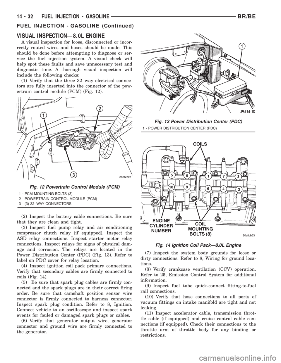
(1) Verify that the three 32±way electrical connec-
tors are fully inserted into the connector of the pow-
ertrain control module (PCM) (Fig. 12).
(2) Inspect the battery cable connections. Be sure
that they are clean and tight.
(3) Inspect fuel pump relay and air conditioning
compressor clutch relay (if equipped). Inspect the
ASD relay connections. Inspect starter motor relay
connections. Inspect relays for signs of physical dam-
age and corrosion. The relays are located in the
Power Distribution Center (PDC) (Fig. 13). Refer to
label on PDC cover for relay location.
(4) Inspect ignition coil pack primary connections.
Verify that secondary cables are firmly connected to
coils (Fig. 14).
(5) Be sure that spark plug cables are firmly con-
nected and the spark plugs are in their correct firing
order. Be sure that camshaft position sensor wire
connector is firmly connected to harness connector.
Inspect spark plug condition. Refer to 8, Ignition.
Connect vehicle to an oscilloscope and inspect spark
events for fouled or damaged spark plugs or cables.
(6) Verify that generator output wire, generator
connector and ground wire are firmly connected to
the generator.(7) Inspect the system body grounds for loose or
dirty connections. Refer to 8, Wiring for ground loca-
tions.
(8) Verify crankcase ventilation (CCV) operation.
Refer to 25, Emission Control System for additional
information.
(9) Inspect fuel tube quick-connect fitting-to-fuel
rail connections.
(10) Verify that hose connections to all ports of
vacuum fittings on intake manifold are tight and not
leaking.
(11) Inspect accelerator cable, transmission throt-
tle cable (if equipped) and cruise control cable con-
nections (if equipped). Check their connections to the
throttle arm of throttle body for any binding or
restrictions.
Fig. 12 Powertrain Control Module (PCM)
1 - PCM MOUNTING BOLTS (3)
2 - POWERTRAIN CONTROL MODULE (PCM)
3 - (3) 32±WAY CONNECTORS
Fig. 13 Power Distribution Center (PDC)
1 - POWER DISTRIBUTION CENTER (PDC)
Fig. 14 Ignition Coil PackÐ8.0L Engine
14 - 32 FUEL INJECTION - GASOLINEBR/BE
FUEL INJECTION - GASOLINE (Continued)
Page 1528 of 2889

(5) Install new plastic tie strap (Fig. 28) to secure
sensor pigtail harness to side of engine block. Thread
tie strap through casting hole on cylinder block.
FUEL PUMP RELAY
DESCRIPTION
The 5±pin, 12±volt, fuel pump relay is located in
the Power Distribution Center (PDC). Refer to the
label on the PDC cover for relay location.
OPERATION
The Powertrain Control Module (PCM) energizes
the electric fuel pump through the fuel pump relay.
The fuel pump relay is energized by first applying
battery voltage to it when the ignition key is turned
ON, and then applying a ground signal to the relay
from the PCM.
Whenever the ignition key is turned ON, the elec-
tric fuel pump will operate. But, the PCM will shut-
down the ground circuit to the fuel pump relay in
approximately 1±3 seconds unless the engine is oper-
ating or the starter motor is engaged.
REMOVAL
The fuel pump relay is located in the Power Distri-
bution Center (PDC) (Fig. 31). Refer to label on PDC
cover for relay location.
(1) Remove PDC cover.
(2) Remove relay from PDC.
(3) Check condition of relay terminals and PDC
connector terminals for damage or corrosion. Repair
if necessary before installing relay.
(4) Check for pin height (pin height should be the
same for all terminals within the PDC connector).
Repair if necessary before installing relay.
INSTALLATION
The fuel pump relay is located in the Power Distri-
bution Center (PDC) (Fig. 31). Refer to label on PDC
cover for relay location.
(1) Install relay to PDC.
(2) Install cover to PDC.
IDLE AIR CONTROL MOTOR
DESCRIPTION
The IAC stepper motor is mounted to the throttle
body, and regulates the amount of air bypassing the
control of the throttle plate. As engine loads and
ambient temperatures change, engine rpm changes.
A pintle on the IAC stepper motor protrudes into a
passage in the throttle body, controlling air flow
through the passage. The IAC is controlled by the
Powertrain Control Module (PCM) to maintain the
target engine idle speed.
OPERATION
At idle, engine speed can be increased by retract-
ing the IAC motor pintle and allowing more air to
pass through the port, or it can be decreased by
restricting the passage with the pintle and diminish-
ing the amount of air bypassing the throttle plate.
The IAC is called a stepper motor because it is
moved (rotated) in steps, or increments. Opening the
IAC opens an air passage around the throttle blade
which increases RPM.
The PCM uses the IAC motor to control idle speed
(along with timing) and to reach a desired MAP dur-
ing decel (keep engine from stalling).
The IAC motor has 4 wires with 4 circuits. Two of
the wires are for 12 volts and ground to supply electri-
cal current to the motor windings to operate the step-
per motor in one direction. The other 2 wires are also
for 12 volts and ground to supply electrical current to
operate the stepper motor in the opposite direction.
To make the IAC go in the opposite direction, the
PCM just reverses polarity on both windings. If only
1 wire is open, the IAC can only be moved 1 step
(increment) in either direction. To keep the IAC
motor in position when no movement is needed, the
PCM will energize both windings at the same time.
This locks the IAC motor in place.
In the IAC motor system, the PCM will count
every step that the motor is moved. This allows the
PCM to determine the motor pintle position. If the
memory is cleared, the PCM no longer knows the
position of the pintle. So at the first key ON, the
PCM drives the IAC motor closed, regardless of
where it was before. This zeros the counter. From
this point the PCM will back out the IAC motor and
keep track of its position again.
Fig. 31 Power Distribution Center (PDC)
1 - POWER DISTRIBUTION CENTER (PDC)
BR/BEFUEL INJECTION - GASOLINE 14 - 41
CRANKSHAFT POSITION SENSOR (Continued)
Page 1549 of 2889
(e) Connect electrical connector to WIF sensor.
(f) Install fuel filter. Refer to previous steps.
(4)Fuel Heater Element:
(a) Do not install fuel filter until heater element
is installed.
(b) Position heater element into filter housing
(fingers downward). Lock fingers into housing.
(c) Install new o-ring to electrical connector
(where connector passes through filter housing).
Apply a light film of clean diesel oil to o-ring seal.
Press this connector into filter housing until it
snaps into heater element.
(d) Install temperature sensor housing and 2
mounting screws to fuel filter housing.
(e) Connect electrical connector.
(f) Install fuel filter. Refer to previous steps.
(5)Drain Valve:
(a) Install 2 new o-rings to valve and filter hous-
ing.
(b) Apply a light film of clean diesel oil to both
seals.
(c) Position valve to filter housing.
(d) Install 4 mounting screws and tighten to 3±5
N´m (30±40 in. lbs.) torque.
(e) Connect drain hose to drain valve.
(f) Install fuel filter. Refer to previous steps.
(6) Start engine and check for leaks.
FUEL HEATER
DESCRIPTION
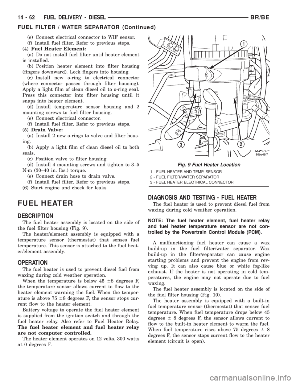
The fuel heater assembly is located on the side of
the fuel filter housing (Fig. 9).
The heater/element assembly is equipped with a
temperature sensor (thermostat) that senses fuel
temperature. This sensor is attached to the fuel heat-
er/element assembly.
OPERATION
The fuel heater is used to prevent diesel fuel from
waxing during cold weather operation.
When the temperature is below 4568 degrees F,
the temperature sensor allows current to flow to the
heater element warming the fuel. When the temper-
ature is above 7568 degrees F, the sensor stops cur-
rent flow to the heater element.
Battery voltage to operate the fuel heater element
is supplied from the ignition switch and through the
fuel heater relay. Also refer to Fuel Heater Relay.
The fuel heater element and fuel heater relay
are not computer controlled.
The heater element operates on 12 volts, 300 watts
at 0 degrees F.
DIAGNOSIS AND TESTING - FUEL HEATER
The fuel heater is used to prevent diesel fuel from
waxing during cold weather operation.
NOTE: The fuel heater element, fuel heater relay
and fuel heater temperature sensor are not con-
trolled by the Powertrain Control Module (PCM).
A malfunctioning fuel heater can cause a wax
build-up in the fuel filter/water separator. Wax
build-up in the filter/separator can cause engine
starting problems and prevent the engine from rev-
ving up. It can also cause blue or white fog-like
exhaust. If the heater is not operating in cold tem-
peratures, the engine may not operate due to fuel
waxing.
The fuel heater assembly is located on the side of
the fuel filter housing (Fig. 10).
The heater assembly is equipped with a built-in
fuel temperature sensor (thermostat) that senses fuel
temperature. When fuel temperature drops below 45
degrees68 degrees F, the sensor allows current to
flow to the built-in heater element to warm the fuel.
When fuel temperature rises above 75 degrees68
degrees F, the sensor stops current flow to the heater
element (circuit is open).
Fig. 9 Fuel Heater Location
1 - FUEL HEATER AND TEMP. SENSOR
2 - FUEL FILTER/WATER SEPARATOR
3 - FUEL HEATER ELECTRICAL CONNECTOR
14 - 62 FUEL DELIVERY - DIESELBR/BE
FUEL FILTER / WATER SEPARATOR (Continued)
Page 1550 of 2889
Voltage to operate the fuel heater element is sup-
plied from the ignition switch, through the fuel
heater relay (also refer to Fuel Heater Relay), to the
fuel temperature sensor and on to the fuel heater ele-
ment.
The heater element operates on 12 volts, 300 watts
at 0 degrees F. As temperature increases, power
requirements decrease.
A minimum of 7 volts is required to operate the
fuel heater. The resistance value of the heater ele-
ment is less than 1 ohm (cold) and up to 1000 ohms
warm.
TESTING
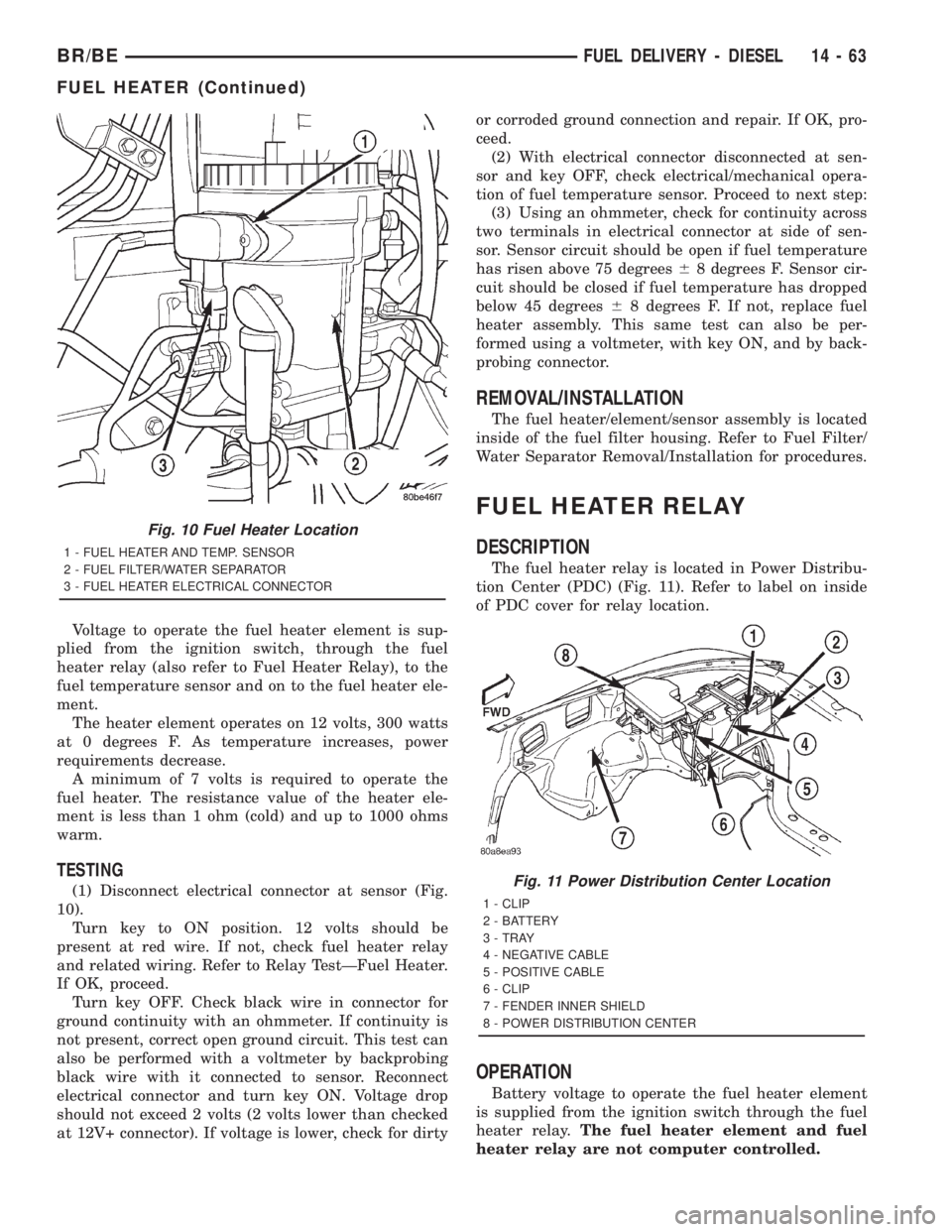
(1) Disconnect electrical connector at sensor (Fig.
10).
Turn key to ON position. 12 volts should be
present at red wire. If not, check fuel heater relay
and related wiring. Refer to Relay TestÐFuel Heater.
If OK, proceed.
Turn key OFF. Check black wire in connector for
ground continuity with an ohmmeter. If continuity is
not present, correct open ground circuit. This test can
also be performed with a voltmeter by backprobing
black wire with it connected to sensor. Reconnect
electrical connector and turn key ON. Voltage drop
should not exceed 2 volts (2 volts lower than checked
at 12V+ connector). If voltage is lower, check for dirtyor corroded ground connection and repair. If OK, pro-
ceed.
(2) With electrical connector disconnected at sen-
sor and key OFF, check electrical/mechanical opera-
tion of fuel temperature sensor. Proceed to next step:
(3) Using an ohmmeter, check for continuity across
two terminals in electrical connector at side of sen-
sor. Sensor circuit should be open if fuel temperature
has risen above 75 degrees68 degrees F. Sensor cir-
cuit should be closed if fuel temperature has dropped
below 45 degrees68 degrees F. If not, replace fuel
heater assembly. This same test can also be per-
formed using a voltmeter, with key ON, and by back-
probing connector.
REMOVAL/INSTALLATION
The fuel heater/element/sensor assembly is located
inside of the fuel filter housing. Refer to Fuel Filter/
Water Separator Removal/Installation for procedures.
FUEL HEATER RELAY
DESCRIPTION
The fuel heater relay is located in Power Distribu-
tion Center (PDC) (Fig. 11). Refer to label on inside
of PDC cover for relay location.
OPERATION
Battery voltage to operate the fuel heater element
is supplied from the ignition switch through the fuel
heater relay.The fuel heater element and fuel
heater relay are not computer controlled.
Fig. 10 Fuel Heater Location
1 - FUEL HEATER AND TEMP. SENSOR
2 - FUEL FILTER/WATER SEPARATOR
3 - FUEL HEATER ELECTRICAL CONNECTOR
Fig. 11 Power Distribution Center Location
1 - CLIP
2 - BATTERY
3 - TRAY
4 - NEGATIVE CABLE
5 - POSITIVE CABLE
6 - CLIP
7 - FENDER INNER SHIELD
8 - POWER DISTRIBUTION CENTER
BR/BEFUEL DELIVERY - DIESEL 14 - 63
FUEL HEATER (Continued)
Page 1551 of 2889
DIAGNOSIS AND TESTING - FUEL HEATER
RELAY
The fuel heater relay is located in the Power Dis-
tribution Center (PDC). Refer to label under PDC
cover for relay location.
To test the fuel heater, refer to Fuel Heater Test.
To test the heater relay only, refer to following:
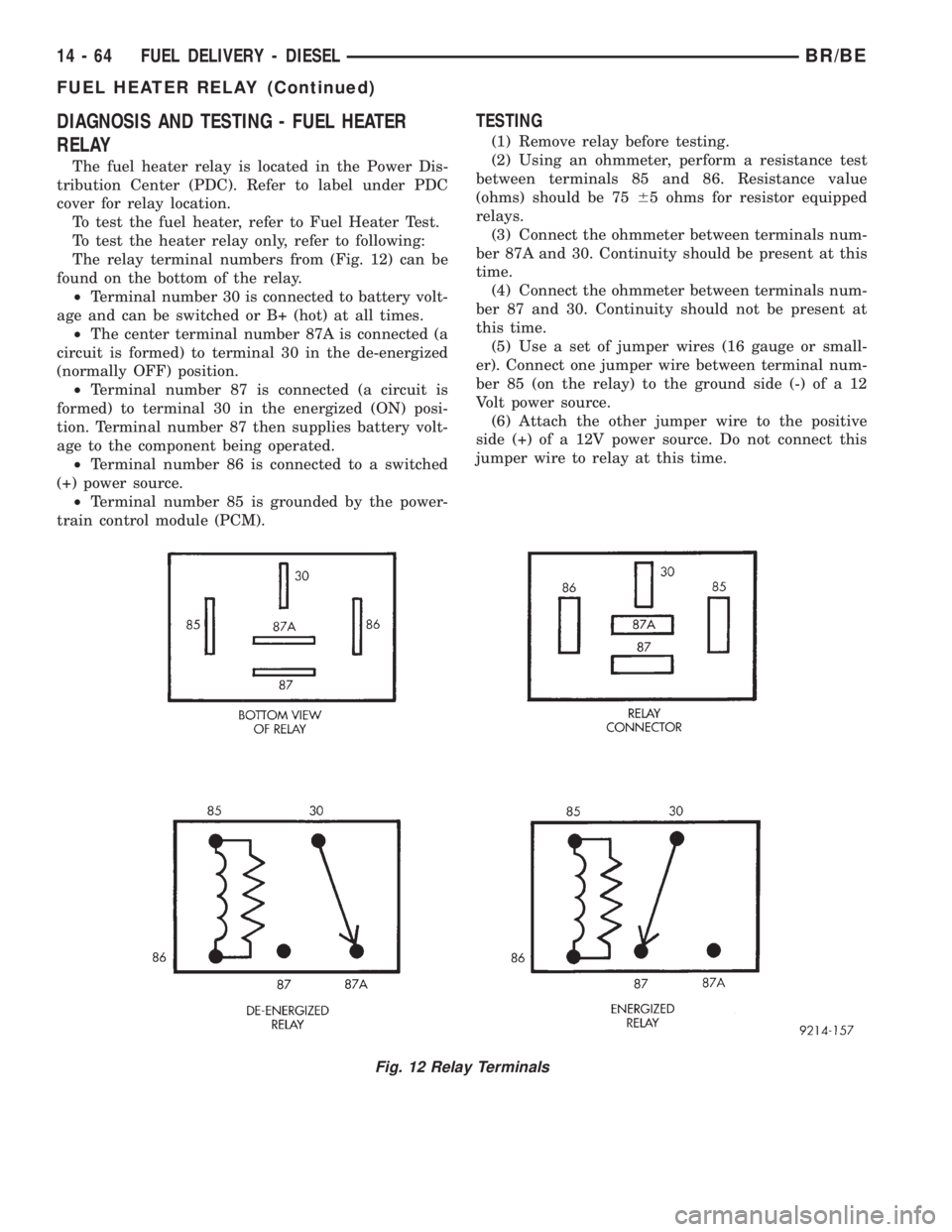
The relay terminal numbers from (Fig. 12) can be
found on the bottom of the relay.
²Terminal number 30 is connected to battery volt-
age and can be switched or B+ (hot) at all times.
²The center terminal number 87A is connected (a
circuit is formed) to terminal 30 in the de-energized
(normally OFF) position.
²Terminal number 87 is connected (a circuit is
formed) to terminal 30 in the energized (ON) posi-
tion. Terminal number 87 then supplies battery volt-
age to the component being operated.
²Terminal number 86 is connected to a switched
(+) power source.
²Terminal number 85 is grounded by the power-
train control module (PCM).
TESTING
(1) Remove relay before testing.
(2) Using an ohmmeter, perform a resistance test
between terminals 85 and 86. Resistance value
(ohms) should be 7565 ohms for resistor equipped
relays.
(3) Connect the ohmmeter between terminals num-
ber 87A and 30. Continuity should be present at this
time.
(4) Connect the ohmmeter between terminals num-
ber 87 and 30. Continuity should not be present at
this time.
(5) Use a set of jumper wires (16 gauge or small-
er). Connect one jumper wire between terminal num-
ber 85 (on the relay) to the ground side (-) of a 12
Volt power source.
(6) Attach the other jumper wire to the positive
side (+) of a 12V power source. Do not connect this
jumper wire to relay at this time.
Fig. 12 Relay Terminals
14 - 64 FUEL DELIVERY - DIESELBR/BE
FUEL HEATER RELAY (Continued)
Page 1552 of 2889
CAUTION: Do not allow the ohmmeter to contact
terminals 85 or 86 during these tests. Damage to
ohmmeter may result.
(7) Attach the other jumper wire (12V +) to termi-
nal number 86. This will activate the relay. Continu-
ity should now be present between terminals number
87 and 30. Continuity should not be present between
terminals number 87A and 30.
(8) Disconnect jumper wires from relay and 12 Volt
power source.
(9) If continuity or resistance tests did not pass,
replace relay. If tests passed, refer to 8, Wiring Dia-
grams for (fuel system) relay wiring schematics and
for additional circuit information.
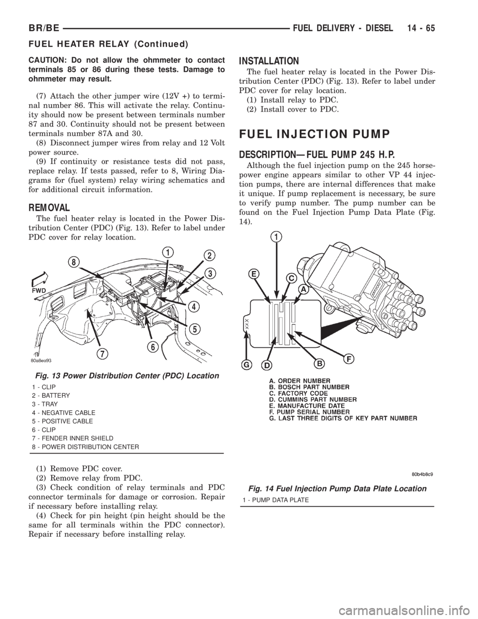
REMOVAL
The fuel heater relay is located in the Power Dis-
tribution Center (PDC) (Fig. 13). Refer to label under
PDC cover for relay location.
(1) Remove PDC cover.
(2) Remove relay from PDC.
(3) Check condition of relay terminals and PDC
connector terminals for damage or corrosion. Repair
if necessary before installing relay.
(4) Check for pin height (pin height should be the
same for all terminals within the PDC connector).
Repair if necessary before installing relay.
INSTALLATION
The fuel heater relay is located in the Power Dis-
tribution Center (PDC) (Fig. 13). Refer to label under
PDC cover for relay location.
(1) Install relay to PDC.
(2) Install cover to PDC.
FUEL INJECTION PUMP
DESCRIPTIONÐFUEL PUMP 245 H.P.
Although the fuel injection pump on the 245 horse-
power engine appears similar to other VP 44 injec-
tion pumps, there are internal differences that make
it unique. If pump replacement is necessary, be sure
to verify pump number. The pump number can be
found on the Fuel Injection Pump Data Plate (Fig.
14).
Fig. 13 Power Distribution Center (PDC) Location
1 - CLIP
2 - BATTERY
3 - TRAY
4 - NEGATIVE CABLE
5 - POSITIVE CABLE
6 - CLIP
7 - FENDER INNER SHIELD
8 - POWER DISTRIBUTION CENTER
Fig. 14 Fuel Injection Pump Data Plate Location
1 - PUMP DATA PLATE
BR/BEFUEL DELIVERY - DIESEL 14 - 65
FUEL HEATER RELAY (Continued)
Page 1560 of 2889
(15) Connect 9±way electrical connector to Fuel
Pump Control Module (FPCM) (Fig. 22).
(16) Connect both negative battery cables to both
batteries.
(17) Bleed air from fuel system.(Refer to 14 -
FUEL SYSTEM/FUEL DELIVERY - STANDARD
PROCEDURE).
(18) Check system for fuel or engine oil leaks.
FUEL INJECTION PUMP DATA
PLATE
SPECIFICATIONS
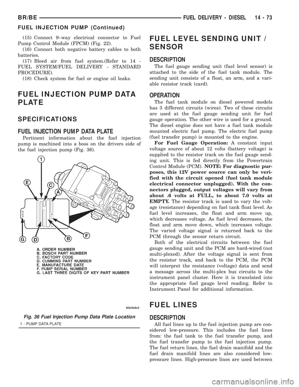
FUEL INJECTION PUMP DATA PLATE
Pertinent information about the fuel injection
pump is machined into a boss on the drivers side of
the fuel injection pump (Fig. 36).
FUEL LEVEL SENDING UNIT /
SENSOR
DESCRIPTION
The fuel gauge sending unit (fuel level sensor) is
attached to the side of the fuel tank module. The
sending unit consists of a float, an arm, and a vari-
able resistor track (card).
OPERATION
The fuel tank module on diesel powered models
has 3 different circuits (wires). Two of these circuits
are used at the fuel gauge sending unit for fuel
gauge operation. The other wire is used for a ground.
The diesel engine does not have a fuel tank module
mounted electric fuel pump. The electric fuel pump
(fuel transfer pump) is mounted to the engine.
For Fuel Gauge Operation:A constant input
voltage source of about 12 volts (battery voltage) is
supplied to the resistor track on the fuel gauge send-
ing unit. This is fed directly from the Powertrain
Control Module (PCM).NOTE: For diagnostic pur-
poses, this 12V power source can only be veri-
fied with the circuit opened (fuel tank module
electrical connector unplugged). With the con-
nectors plugged, output voltages will vary from
about .6 volts at FULL, to about 7.0 volts at
EMPTY.The resistor track is used to vary the volt-
age (resistance) depending on fuel tank float level. As
fuel level increases, the float and arm move up,
which decreases voltage. As fuel level decreases, the
float and arm move down, which increases voltage.
The varied voltage signal is returned back to the
PCM through the sensor return circuit.
Both of the electrical circuits between the fuel
gauge sending unit and the PCM are hard-wired (not
multi-plexed). After the voltage signal is sent from
the resistor track, and back to the PCM, the PCM
will interpret the resistance (voltage) data and send
a message across the multi-plex bus circuits to the
instrument panel cluster. Here it is translated into
the appropriate fuel gauge level reading. Refer to
Instrument Panel for additional information.
FUEL LINES
DESCRIPTION
All fuel lines up to the fuel injection pump are con-
sidered low-pressure. This includes the fuel lines
from: the fuel tank to the fuel transfer pump, and
the fuel transfer pump to the fuel injection pump.
The fuel return lines, the fuel drain manifold and the
fuel drain manifold lines are also considered low-
pressure lines. High-pressure lines are used between
Fig. 36 Fuel Injection Pump Data Plate Location
1 - PUMP DATA PLATE
BR/BEFUEL DELIVERY - DIESEL 14 - 73
FUEL INJECTION PUMP (Continued)
Page 1570 of 2889
REMOVAL
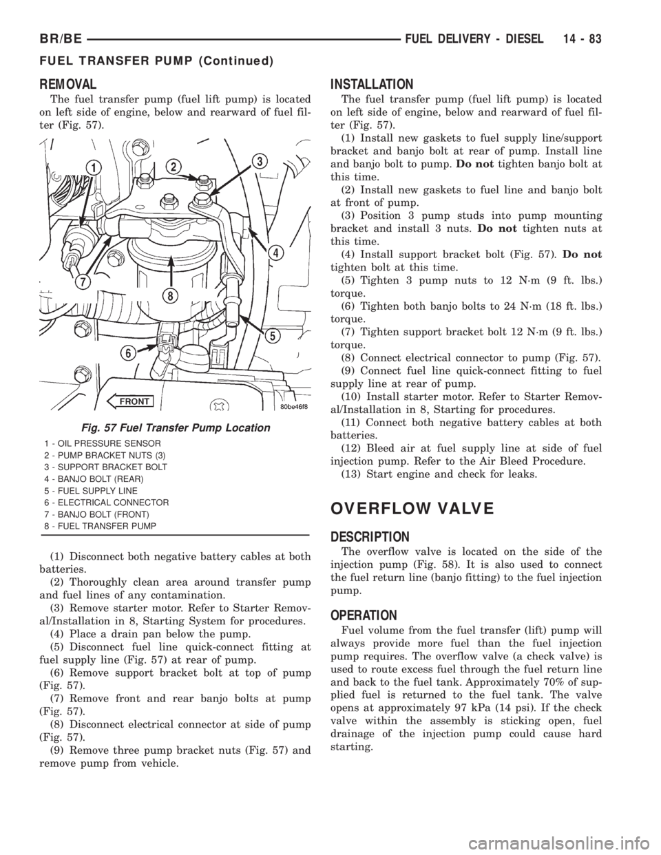
The fuel transfer pump (fuel lift pump) is located
on left side of engine, below and rearward of fuel fil-
ter (Fig. 57).
(1) Disconnect both negative battery cables at both
batteries.
(2) Thoroughly clean area around transfer pump
and fuel lines of any contamination.
(3) Remove starter motor. Refer to Starter Remov-
al/Installation in 8, Starting System for procedures.
(4) Place a drain pan below the pump.
(5) Disconnect fuel line quick-connect fitting at
fuel supply line (Fig. 57) at rear of pump.
(6) Remove support bracket bolt at top of pump
(Fig. 57).
(7) Remove front and rear banjo bolts at pump
(Fig. 57).
(8) Disconnect electrical connector at side of pump
(Fig. 57).
(9) Remove three pump bracket nuts (Fig. 57) and
remove pump from vehicle.
INSTALLATION
The fuel transfer pump (fuel lift pump) is located
on left side of engine, below and rearward of fuel fil-
ter (Fig. 57).
(1) Install new gaskets to fuel supply line/support
bracket and banjo bolt at rear of pump. Install line
and banjo bolt to pump.Do nottighten banjo bolt at
this time.
(2) Install new gaskets to fuel line and banjo bolt
at front of pump.
(3) Position 3 pump studs into pump mounting
bracket and install 3 nuts.Do nottighten nuts at
this time.
(4) Install support bracket bolt (Fig. 57).Do not
tighten bolt at this time.
(5) Tighten 3 pump nuts to 12 N´m (9 ft. lbs.)
torque.
(6) Tighten both banjo bolts to 24 N´m (18 ft. lbs.)
torque.
(7) Tighten support bracket bolt 12 N´m (9 ft. lbs.)
torque.
(8) Connect electrical connector to pump (Fig. 57).
(9) Connect fuel line quick-connect fitting to fuel
supply line at rear of pump.
(10) Install starter motor. Refer to Starter Remov-
al/Installation in 8, Starting for procedures.
(11) Connect both negative battery cables at both
batteries.
(12) Bleed air at fuel supply line at side of fuel
injection pump. Refer to the Air Bleed Procedure.
(13) Start engine and check for leaks.
OVERFLOW VALVE
DESCRIPTION
The overflow valve is located on the side of the
injection pump (Fig. 58). It is also used to connect
the fuel return line (banjo fitting) to the fuel injection
pump.
OPERATION
Fuel volume from the fuel transfer (lift) pump will
always provide more fuel than the fuel injection
pump requires. The overflow valve (a check valve) is
used to route excess fuel through the fuel return line
and back to the fuel tank. Approximately 70% of sup-
plied fuel is returned to the fuel tank. The valve
opens at approximately 97 kPa (14 psi). If the check
valve within the assembly is sticking open, fuel
drainage of the injection pump could cause hard
starting.
Fig. 57 Fuel Transfer Pump Location
1 - OIL PRESSURE SENSOR
2 - PUMP BRACKET NUTS (3)
3 - SUPPORT BRACKET BOLT
4 - BANJO BOLT (REAR)
5 - FUEL SUPPLY LINE
6 - ELECTRICAL CONNECTOR
7 - BANJO BOLT (FRONT)
8 - FUEL TRANSFER PUMP
BR/BEFUEL DELIVERY - DIESEL 14 - 83
FUEL TRANSFER PUMP (Continued)