2001 DODGE RAM battery location
[x] Cancel search: battery locationPage 2683 of 2889
(5) Remove the cluster bezel from the instrument
panel.
INSTALLATION
WARNING: ON VEHICLES EQUIPPED WITH AIR-
BAGS, DISABLE THE AIRBAG SYSTEM BEFORE
ATTEMPTING ANY STEERING WHEEL, STEERING
COLUMN, OR INSTRUMENT PANEL COMPONENT
DIAGNOSIS OR SERVICE. DISCONNECT AND ISO-
LATE THE BATTERY NEGATIVE (GROUND) CABLE,
THEN WAIT TWO MINUTES FOR THE AIRBAG SYS-
TEM CAPACITOR TO DISCHARGE BEFORE PER-
FORMING FURTHER DIAGNOSIS OR SERVICE. THIS
IS THE ONLY SURE WAY TO DISABLE THE AIRBAG
SYSTEM. FAILURE TO TAKE THE PROPER PRE-
CAUTIONS COULD RESULT IN ACCIDENTAL AIR-
BAG DEPLOYMENT AND POSSIBLE PERSONAL
INJURY.
(1) Position the cluster bezel to the instrument
panel (Fig. 3).
(2) Align the snap clips on the cluster bezel with
the receptacles in the instrument panel.
(3) Press firmly on the cluster bezel over each of
the snap clip locations until each of the snap clips is
fully engaged in its receptacle.
(4) Reconnect the battery negative cable.
CUBBY BIN
REMOVAL
WARNING: ON VEHICLES EQUIPPED WITH AIR-
BAGS, DISABLE THE AIRBAG SYSTEM BEFORE
ATTEMPTING ANY STEERING WHEEL, STEERING
COLUMN, OR INSTRUMENT PANEL COMPONENT
DIAGNOSIS OR SERVICE. DISCONNECT AND ISO-
LATE THE BATTERY NEGATIVE (GROUND) CABLE,
THEN WAIT TWO MINUTES FOR THE AIRBAG SYS-
TEM CAPACITOR TO DISCHARGE BEFORE PER-
FORMING FURTHER DIAGNOSIS OR SERVICE. THIS
IS THE ONLY SURE WAY TO DISABLE THE AIRBAG
SYSTEM. FAILURE TO TAKE THE PROPER PRE-
CAUTIONS COULD RESULT IN ACCIDENTAL AIR-
BAG DEPLOYMENT AND POSSIBLE PERSONAL
INJURY.
(1) Disconnect and isolate the battery negative
cable.
(2) Remove the cluster bezel from the instrument
panel. (Refer to 23 - BODY/INSTRUMENT PANEL/
CLUSTER BEZEL - REMOVAL).
(3) Remove the three screws that secure the cubby
bin to the instrument panel (Fig. 4).(4) Remove the cubby bin from the instrument
panel.
INSTALLATION
WARNING: ON VEHICLES EQUIPPED WITH AIR-
BAGS, DISABLE THE AIRBAG SYSTEM BEFORE
ATTEMPTING ANY STEERING WHEEL, STEERING
COLUMN, OR INSTRUMENT PANEL COMPONENT
DIAGNOSIS OR SERVICE. DISCONNECT AND ISO-
LATE THE BATTERY NEGATIVE (GROUND) CABLE,
THEN WAIT TWO MINUTES FOR THE AIRBAG SYS-
TEM CAPACITOR TO DISCHARGE BEFORE PER-
FORMING FURTHER DIAGNOSIS OR SERVICE. THIS
IS THE ONLY SURE WAY TO DISABLE THE AIRBAG
SYSTEM. FAILURE TO TAKE THE PROPER PRE-
CAUTIONS COULD RESULT IN ACCIDENTAL AIR-
BAG DEPLOYMENT AND POSSIBLE PERSONAL
INJURY.
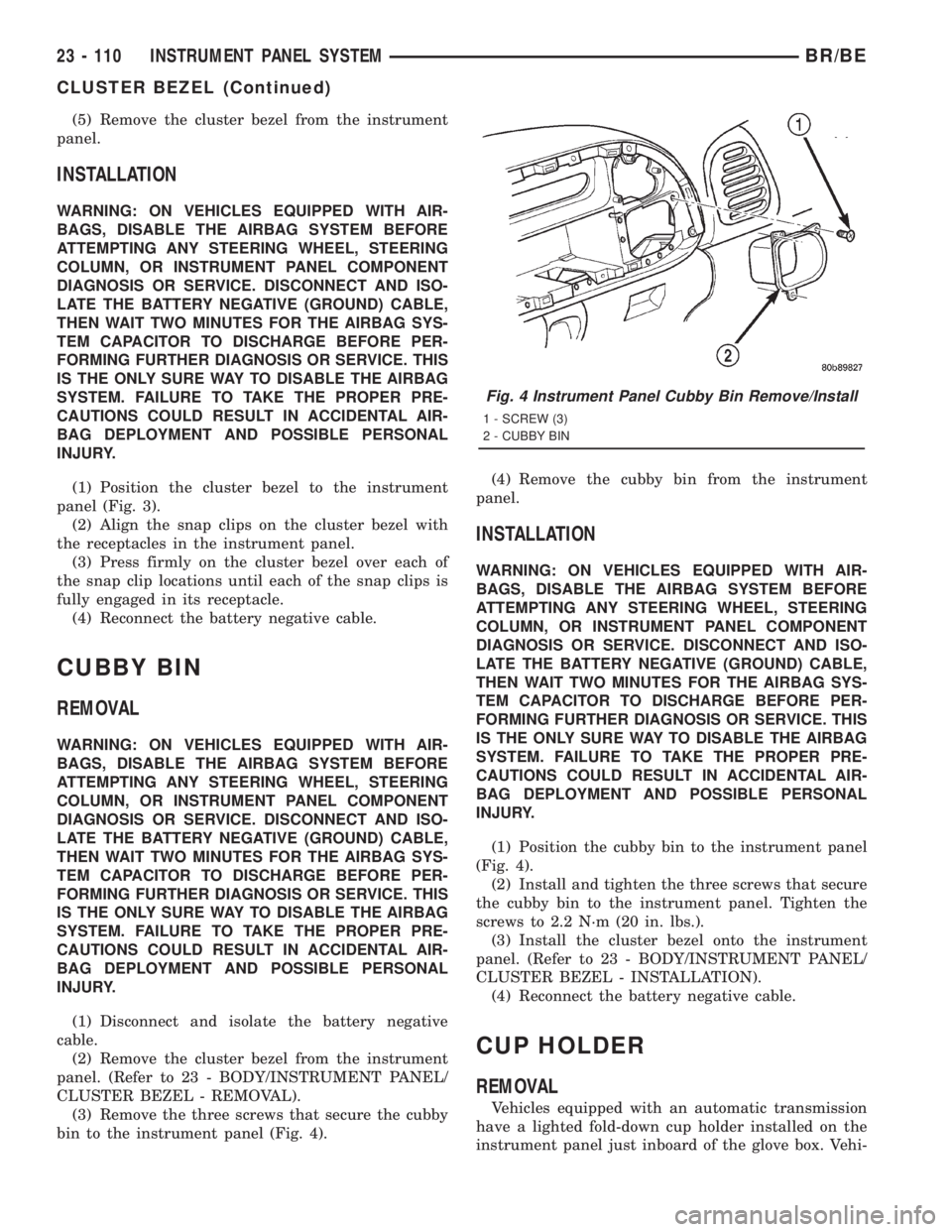
(1) Position the cubby bin to the instrument panel
(Fig. 4).
(2) Install and tighten the three screws that secure
the cubby bin to the instrument panel. Tighten the
screws to 2.2 N´m (20 in. lbs.).
(3) Install the cluster bezel onto the instrument
panel. (Refer to 23 - BODY/INSTRUMENT PANEL/
CLUSTER BEZEL - INSTALLATION).
(4) Reconnect the battery negative cable.
CUP HOLDER
REMOVAL
Vehicles equipped with an automatic transmission
have a lighted fold-down cup holder installed on the
instrument panel just inboard of the glove box. Vehi-
Fig. 4 Instrument Panel Cubby Bin Remove/Install
1 - SCREW (3)
2 - CUBBY BIN
23 - 110 INSTRUMENT PANEL SYSTEMBR/BE
CLUSTER BEZEL (Continued)
Page 2689 of 2889
bezel on each side of the steering column away from
the instrument panel far enough to disengage the
snap clip retainers from their receptacles in the
instrument panel.
(4) Remove the steering column opening cover
from the instrument panel.
INSTALLATION
WARNING: ON VEHICLES EQUIPPED WITH AIR-
BAGS, DISABLE THE AIRBAG SYSTEM BEFORE
ATTEMPTING ANY STEERING WHEEL, STEERING
COLUMN, OR INSTRUMENT PANEL COMPONENT
DIAGNOSIS OR SERVICE. DISCONNECT AND ISO-
LATE THE BATTERY NEGATIVE (GROUND) CABLE,
THEN WAIT TWO MINUTES FOR THE AIRBAG SYS-
TEM CAPACITOR TO DISCHARGE BEFORE PER-
FORMING FURTHER DIAGNOSIS OR SERVICE. THIS
IS THE ONLY SURE WAY TO DISABLE THE AIRBAG
SYSTEM. FAILURE TO TAKE THE PROPER PRE-
CAUTIONS COULD RESULT IN ACCIDENTAL AIR-
BAG DEPLOYMENT AND POSSIBLE PERSONAL
INJURY.
(1) Position the steering column opening cover to
the instrument panel (Fig. 10).
(2) Align the snap clip retainers on the steering
column opening cover with their receptacles in the
instrument panel.
(3) Press firmly and evenly on the steering column
opening cover over the snap clip locations until each
of the snap clips is fully engaged in its receptacle.
(4) Install and tighten the three screws that secure
the lower edge of the steering column opening cover
to the lower instrument panel reinforcement. Tighten
the screws to 2.2 N´m (20 in. lbs.).
(5) Reconnect the battery negative cable.
STORAGE BIN
REMOVAL
Vehicles equipped with an automatic transmission
have a lighted fold-down cup holder installed on the
instrument panel just inboard of the glove box. Vehi-
cles equipped with a manual transmission have a
lighted storage bin installed on the instrument panel
in place of the fold-down cup holder.
WARNING: ON VEHICLES EQUIPPED WITH AIR-
BAGS, DISABLE THE AIRBAG SYSTEM BEFORE
ATTEMPTING ANY STEERING WHEEL, STEERING
COLUMN, OR INSTRUMENT PANEL COMPONENT
DIAGNOSIS OR SERVICE. DISCONNECT AND ISO-
LATE THE BATTERY NEGATIVE (GROUND) CABLE,
THEN WAIT TWO MINUTES FOR THE AIRBAG SYS-
TEM CAPACITOR TO DISCHARGE BEFORE PER-FORMING FURTHER DIAGNOSIS OR SERVICE. THIS
IS THE ONLY SURE WAY TO DISABLE THE AIRBAG
SYSTEM. FAILURE TO TAKE THE PROPER PRE-
CAUTIONS COULD RESULT IN ACCIDENTAL AIR-
BAG DEPLOYMENT AND POSSIBLE PERSONAL
INJURY.
(1) Disconnect and isolate the battery negative
cable.
(2) Remove the cluster bezel from the instrument
panel. (Refer to 23 - BODY/INSTRUMENT PANEL/
CLUSTER BEZEL - REMOVAL).
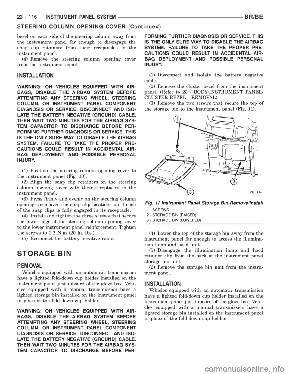
(3) Remove the two screws that secure the top of
the storage bin to the instrument panel (Fig. 11).
(4) Lower the top of the storage bin away from the
instrument panel far enough to access the illumina-
tion lamp and hood unit.
(5) Disengage the illumination lamp and hood
retainer clip from the back of the instrument panel
storage bin unit.
(6) Remove the storage bin unit from the instru-
ment panel.
INSTALLATION
Vehicles equipped with an automatic transmission
have a lighted fold-down cup holder installed on the
instrument panel just inboard of the glove box. Vehi-
cles equipped with a manual transmission have a
lighted storage bin installed on the instrument panel
in place of the fold-down cup holder.
Fig. 11 Instrument Panel Storage Bin Remove/Install
1 - SCREWS
2 - STORAGE BIN (RAISED)
3 - STORAGE BIN (LOWERED)
23 - 116 INSTRUMENT PANEL SYSTEMBR/BE
STEERING COLUMN OPENING COVER (Continued)
Page 2746 of 2889
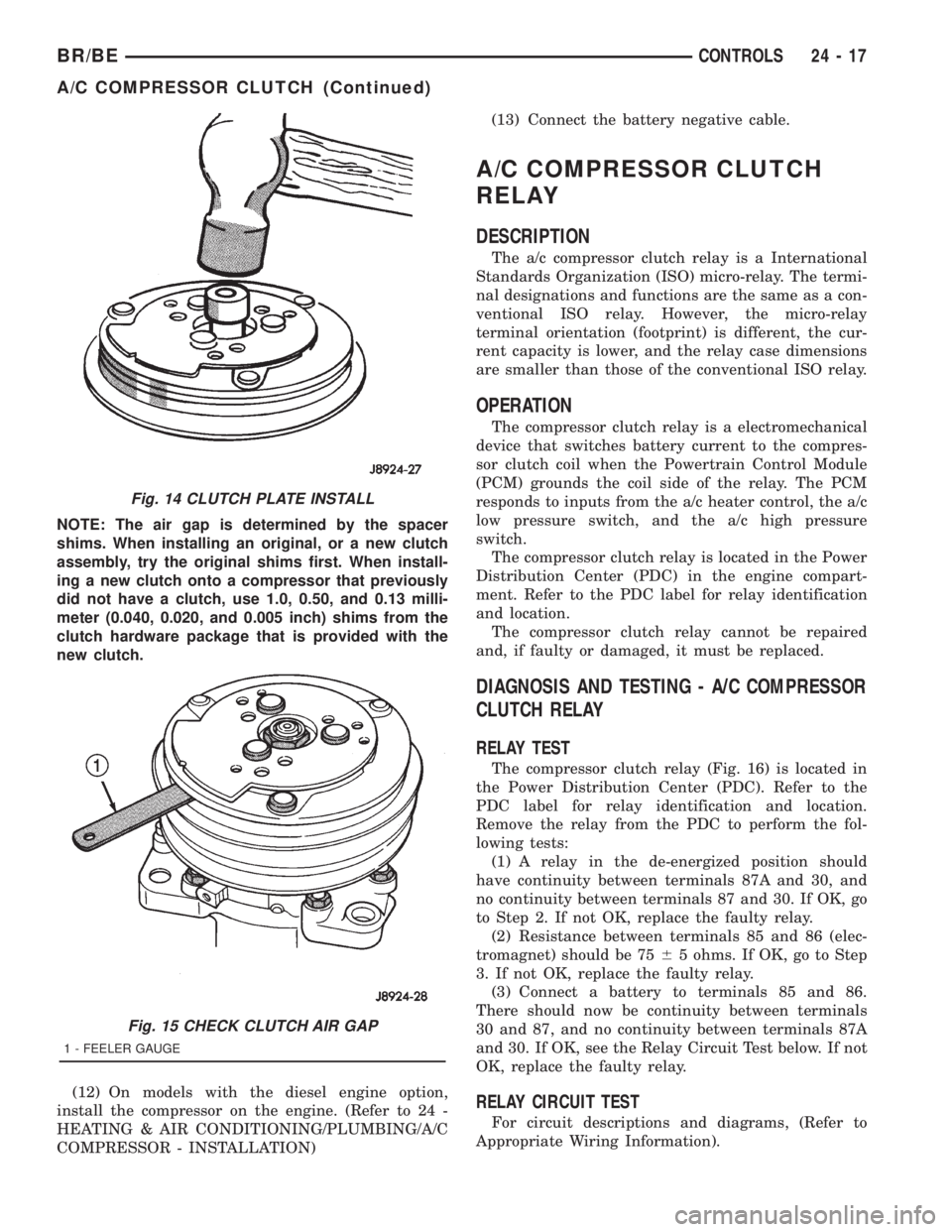
NOTE: The air gap is determined by the spacer
shims. When installing an original, or a new clutch
assembly, try the original shims first. When install-
ing a new clutch onto a compressor that previously
did not have a clutch, use 1.0, 0.50, and 0.13 milli-
meter (0.040, 0.020, and 0.005 inch) shims from the
clutch hardware package that is provided with the
new clutch.
(12) On models with the diesel engine option,
install the compressor on the engine. (Refer to 24 -
HEATING & AIR CONDITIONING/PLUMBING/A/C
COMPRESSOR - INSTALLATION)(13) Connect the battery negative cable.
A/C COMPRESSOR CLUTCH
RELAY
DESCRIPTION
The a/c compressor clutch relay is a International
Standards Organization (ISO) micro-relay. The termi-
nal designations and functions are the same as a con-
ventional ISO relay. However, the micro-relay
terminal orientation (footprint) is different, the cur-
rent capacity is lower, and the relay case dimensions
are smaller than those of the conventional ISO relay.
OPERATION
The compressor clutch relay is a electromechanical
device that switches battery current to the compres-
sor clutch coil when the Powertrain Control Module
(PCM) grounds the coil side of the relay. The PCM
responds to inputs from the a/c heater control, the a/c
low pressure switch, and the a/c high pressure
switch.
The compressor clutch relay is located in the Power
Distribution Center (PDC) in the engine compart-
ment. Refer to the PDC label for relay identification
and location.
The compressor clutch relay cannot be repaired
and, if faulty or damaged, it must be replaced.
DIAGNOSIS AND TESTING - A/C COMPRESSOR
CLUTCH RELAY
RELAY TEST
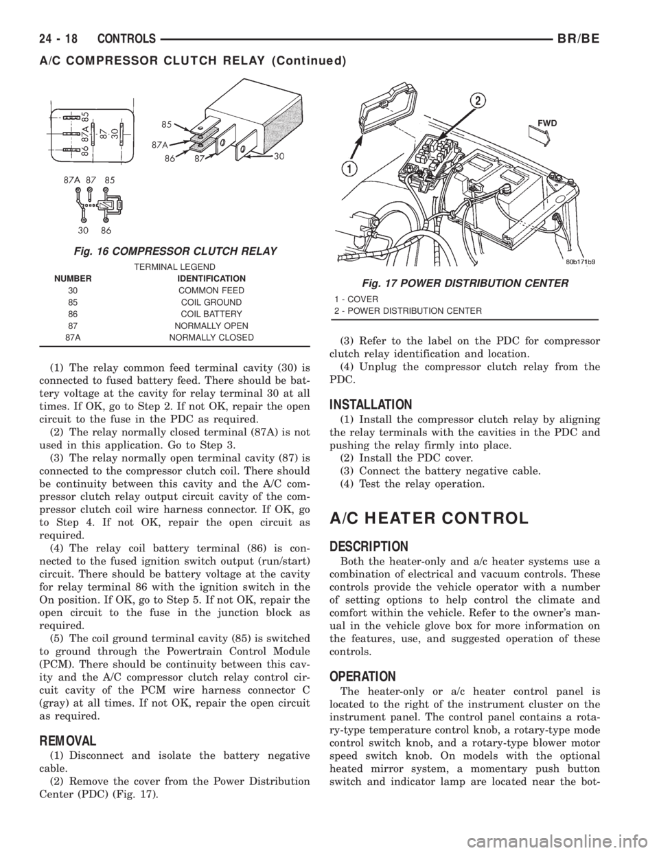
The compressor clutch relay (Fig. 16) is located in
the Power Distribution Center (PDC). Refer to the
PDC label for relay identification and location.
Remove the relay from the PDC to perform the fol-
lowing tests:
(1) A relay in the de-energized position should
have continuity between terminals 87A and 30, and
no continuity between terminals 87 and 30. If OK, go
to Step 2. If not OK, replace the faulty relay.
(2) Resistance between terminals 85 and 86 (elec-
tromagnet) should be 7565 ohms. If OK, go to Step
3. If not OK, replace the faulty relay.
(3) Connect a battery to terminals 85 and 86.
There should now be continuity between terminals
30 and 87, and no continuity between terminals 87A
and 30. If OK, see the Relay Circuit Test below. If not
OK, replace the faulty relay.
RELAY CIRCUIT TEST
For circuit descriptions and diagrams, (Refer to
Appropriate Wiring Information).
Fig. 14 CLUTCH PLATE INSTALL
Fig. 15 CHECK CLUTCH AIR GAP
1 - FEELER GAUGE
BR/BECONTROLS 24 - 17
A/C COMPRESSOR CLUTCH (Continued)
Page 2747 of 2889
(1) The relay common feed terminal cavity (30) is
connected to fused battery feed. There should be bat-
tery voltage at the cavity for relay terminal 30 at all
times. If OK, go to Step 2. If not OK, repair the open
circuit to the fuse in the PDC as required.
(2) The relay normally closed terminal (87A) is not
used in this application. Go to Step 3.
(3) The relay normally open terminal cavity (87) is
connected to the compressor clutch coil. There should
be continuity between this cavity and the A/C com-
pressor clutch relay output circuit cavity of the com-
pressor clutch coil wire harness connector. If OK, go
to Step 4. If not OK, repair the open circuit as
required.
(4) The relay coil battery terminal (86) is con-
nected to the fused ignition switch output (run/start)
circuit. There should be battery voltage at the cavity
for relay terminal 86 with the ignition switch in the
On position. If OK, go to Step 5. If not OK, repair the
open circuit to the fuse in the junction block as
required.
(5) The coil ground terminal cavity (85) is switched
to ground through the Powertrain Control Module
(PCM). There should be continuity between this cav-
ity and the A/C compressor clutch relay control cir-
cuit cavity of the PCM wire harness connector C
(gray) at all times. If not OK, repair the open circuit
as required.
REMOVAL
(1) Disconnect and isolate the battery negative
cable.
(2) Remove the cover from the Power Distribution
Center (PDC) (Fig. 17).(3) Refer to the label on the PDC for compressor
clutch relay identification and location.
(4) Unplug the compressor clutch relay from the
PDC.
INSTALLATION
(1) Install the compressor clutch relay by aligning
the relay terminals with the cavities in the PDC and
pushing the relay firmly into place.
(2) Install the PDC cover.
(3) Connect the battery negative cable.
(4) Test the relay operation.
A/C HEATER CONTROL
DESCRIPTION
Both the heater-only and a/c heater systems use a
combination of electrical and vacuum controls. These
controls provide the vehicle operator with a number
of setting options to help control the climate and
comfort within the vehicle. Refer to the owner's man-
ual in the vehicle glove box for more information on
the features, use, and suggested operation of these
controls.
OPERATION
The heater-only or a/c heater control panel is
located to the right of the instrument cluster on the
instrument panel. The control panel contains a rota-
ry-type temperature control knob, a rotary-type mode
control switch knob, and a rotary-type blower motor
speed switch knob. On models with the optional
heated mirror system, a momentary push button
switch and indicator lamp are located near the bot-
Fig. 16 COMPRESSOR CLUTCH RELAY
TERMINAL LEGEND
NUMBER IDENTIFICATION
30 COMMON FEED
85 COIL GROUND
86 COIL BATTERY
87 NORMALLY OPEN
87A NORMALLY CLOSED
Fig. 17 POWER DISTRIBUTION CENTER
1 - COVER
2 - POWER DISTRIBUTION CENTER
24 - 18 CONTROLSBR/BE
A/C COMPRESSOR CLUTCH RELAY (Continued)
Page 2751 of 2889
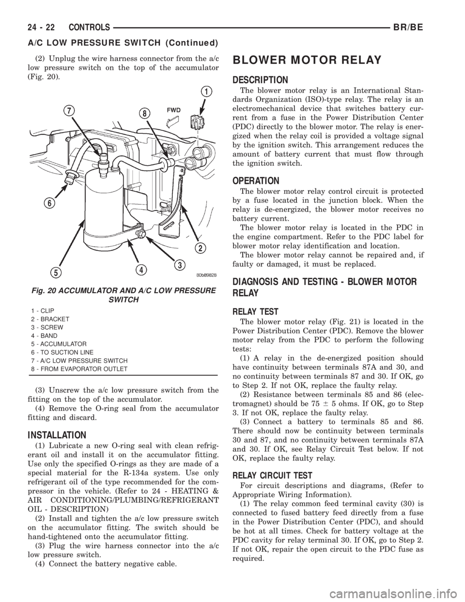
(2) Unplug the wire harness connector from the a/c
low pressure switch on the top of the accumulator
(Fig. 20).
(3) Unscrew the a/c low pressure switch from the
fitting on the top of the accumulator.
(4) Remove the O-ring seal from the accumulator
fitting and discard.
INSTALLATION
(1) Lubricate a new O-ring seal with clean refrig-
erant oil and install it on the accumulator fitting.
Use only the specified O-rings as they are made of a
special material for the R-134a system. Use only
refrigerant oil of the type recommended for the com-
pressor in the vehicle. (Refer to 24 - HEATING &
AIR CONDITIONING/PLUMBING/REFRIGERANT
OIL - DESCRIPTION)
(2) Install and tighten the a/c low pressure switch
on the accumulator fitting. The switch should be
hand-tightened onto the accumulator fitting.
(3) Plug the wire harness connector into the a/c
low pressure switch.
(4) Connect the battery negative cable.
BLOWER MOTOR RELAY
DESCRIPTION
The blower motor relay is an International Stan-
dards Organization (ISO)-type relay. The relay is an
electromechanical device that switches battery cur-
rent from a fuse in the Power Distribution Center
(PDC) directly to the blower motor. The relay is ener-
gized when the relay coil is provided a voltage signal
by the ignition switch. This arrangement reduces the
amount of battery current that must flow through
the ignition switch.
OPERATION
The blower motor relay control circuit is protected
by a fuse located in the junction block. When the
relay is de-energized, the blower motor receives no
battery current.
The blower motor relay is located in the PDC in
the engine compartment. Refer to the PDC label for
blower motor relay identification and location.
The blower motor relay cannot be repaired and, if
faulty or damaged, it must be replaced.
DIAGNOSIS AND TESTING - BLOWER MOTOR
RELAY
RELAY TEST
The blower motor relay (Fig. 21) is located in the
Power Distribution Center (PDC). Remove the blower
motor relay from the PDC to perform the following
tests:
(1) A relay in the de-energized position should
have continuity between terminals 87A and 30, and
no continuity between terminals 87 and 30. If OK, go
to Step 2. If not OK, replace the faulty relay.
(2) Resistance between terminals 85 and 86 (elec-
tromagnet) should be 7565 ohms. If OK, go to Step
3. If not OK, replace the faulty relay.
(3) Connect a battery to terminals 85 and 86.
There should now be continuity between terminals
30 and 87, and no continuity between terminals 87A
and 30. If OK, see Relay Circuit Test below. If not
OK, replace the faulty relay.
RELAY CIRCUIT TEST
For circuit descriptions and diagrams, (Refer to
Appropriate Wiring Information).
(1) The relay common feed terminal cavity (30) is
connected to fused battery feed directly from a fuse
in the Power Distribution Center (PDC), and should
be hot at all times. Check for battery voltage at the
PDC cavity for relay terminal 30. If OK, go to Step 2.
If not OK, repair the open circuit to the PDC fuse as
required.
Fig. 20 ACCUMULATOR AND A/C LOW PRESSURE
SWITCH
1 - CLIP
2 - BRACKET
3 - SCREW
4 - BAND
5 - ACCUMULATOR
6 - TO SUCTION LINE
7 - A/C LOW PRESSURE SWITCH
8 - FROM EVAPORATOR OUTLET
24 - 22 CONTROLSBR/BE
A/C LOW PRESSURE SWITCH (Continued)
Page 2752 of 2889
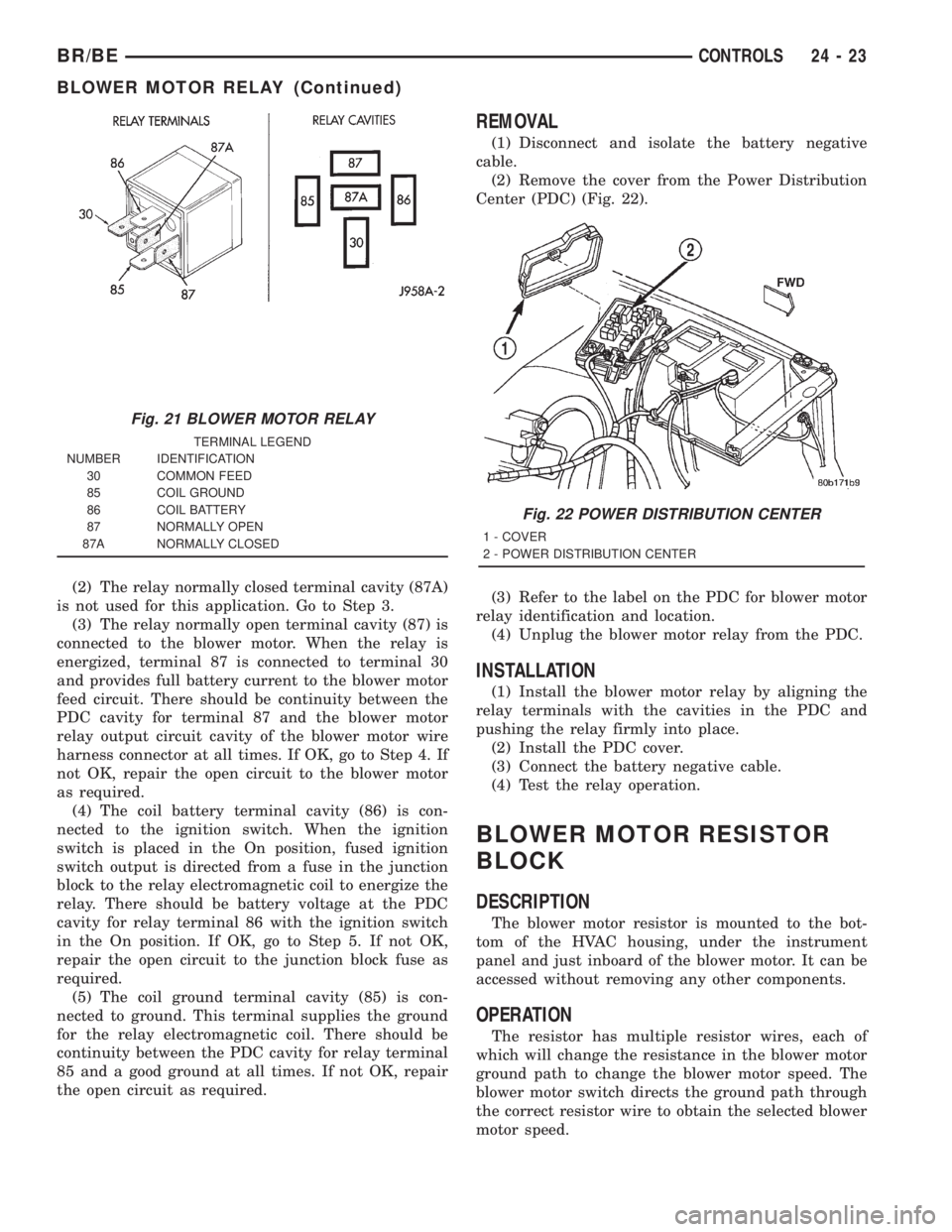
(2) The relay normally closed terminal cavity (87A)
is not used for this application. Go to Step 3.
(3) The relay normally open terminal cavity (87) is
connected to the blower motor. When the relay is
energized, terminal 87 is connected to terminal 30
and provides full battery current to the blower motor
feed circuit. There should be continuity between the
PDC cavity for terminal 87 and the blower motor
relay output circuit cavity of the blower motor wire
harness connector at all times. If OK, go to Step 4. If
not OK, repair the open circuit to the blower motor
as required.
(4) The coil battery terminal cavity (86) is con-
nected to the ignition switch. When the ignition
switch is placed in the On position, fused ignition
switch output is directed from a fuse in the junction
block to the relay electromagnetic coil to energize the
relay. There should be battery voltage at the PDC
cavity for relay terminal 86 with the ignition switch
in the On position. If OK, go to Step 5. If not OK,
repair the open circuit to the junction block fuse as
required.
(5) The coil ground terminal cavity (85) is con-
nected to ground. This terminal supplies the ground
for the relay electromagnetic coil. There should be
continuity between the PDC cavity for relay terminal
85 and a good ground at all times. If not OK, repair
the open circuit as required.
REMOVAL
(1) Disconnect and isolate the battery negative
cable.
(2) Remove the cover from the Power Distribution
Center (PDC) (Fig. 22).
(3) Refer to the label on the PDC for blower motor
relay identification and location.
(4) Unplug the blower motor relay from the PDC.
INSTALLATION
(1) Install the blower motor relay by aligning the
relay terminals with the cavities in the PDC and
pushing the relay firmly into place.
(2) Install the PDC cover.
(3) Connect the battery negative cable.
(4) Test the relay operation.
BLOWER MOTOR RESISTOR
BLOCK
DESCRIPTION
The blower motor resistor is mounted to the bot-
tom of the HVAC housing, under the instrument
panel and just inboard of the blower motor. It can be
accessed without removing any other components.
OPERATION
The resistor has multiple resistor wires, each of
which will change the resistance in the blower motor
ground path to change the blower motor speed. The
blower motor switch directs the ground path through
the correct resistor wire to obtain the selected blower
motor speed.
Fig. 21 BLOWER MOTOR RELAY
TERMINAL LEGEND
NUMBER IDENTIFICATION
30 COMMON FEED
85 COIL GROUND
86 COIL BATTERY
87 NORMALLY OPEN
87A NORMALLY CLOSED
Fig. 22 POWER DISTRIBUTION CENTER
1 - COVER
2 - POWER DISTRIBUTION CENTER
BR/BECONTROLS 24 - 23
BLOWER MOTOR RELAY (Continued)
Page 2779 of 2889
(1) On gasoline engine models:
(a) Insert the two lower condenser locators into
the isolators in the holes of the lower crossmember.
(b) Tilt the condenser up towards the engine
compartment far enough to align the upper mount-
ing bracket holes with the holes in the upper radi-
ator crossmember.
(c) Install the two screws that secure the con-
denser upper mounting brackets to the outside of
the upper radiator crossmember. Tighten the
mounting screws to 10.5 N´m (95 in. lbs.).
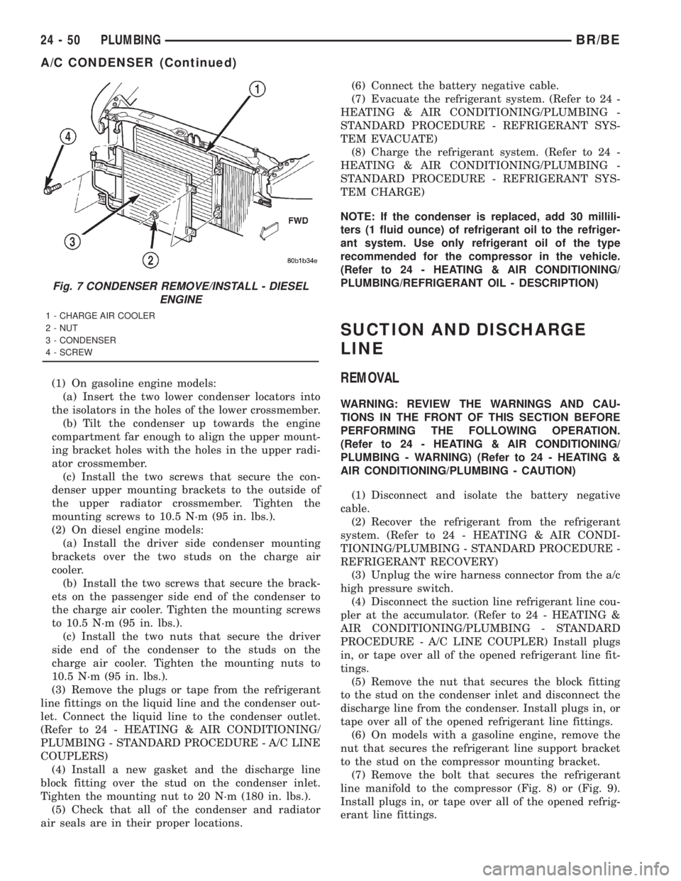
(2) On diesel engine models:
(a) Install the driver side condenser mounting
brackets over the two studs on the charge air
cooler.
(b) Install the two screws that secure the brack-
ets on the passenger side end of the condenser to
the charge air cooler. Tighten the mounting screws
to 10.5 N´m (95 in. lbs.).
(c) Install the two nuts that secure the driver
side end of the condenser to the studs on the
charge air cooler. Tighten the mounting nuts to
10.5 N´m (95 in. lbs.).
(3) Remove the plugs or tape from the refrigerant
line fittings on the liquid line and the condenser out-
let. Connect the liquid line to the condenser outlet.
(Refer to 24 - HEATING & AIR CONDITIONING/
PLUMBING - STANDARD PROCEDURE - A/C LINE
COUPLERS)
(4) Install a new gasket and the discharge line
block fitting over the stud on the condenser inlet.
Tighten the mounting nut to 20 N´m (180 in. lbs.).
(5) Check that all of the condenser and radiator
air seals are in their proper locations.(6) Connect the battery negative cable.
(7) Evacuate the refrigerant system. (Refer to 24 -
HEATING & AIR CONDITIONING/PLUMBING -
STANDARD PROCEDURE - REFRIGERANT SYS-
TEM EVACUATE)
(8) Charge the refrigerant system. (Refer to 24 -
HEATING & AIR CONDITIONING/PLUMBING -
STANDARD PROCEDURE - REFRIGERANT SYS-
TEM CHARGE)
NOTE: If the condenser is replaced, add 30 millili-
ters (1 fluid ounce) of refrigerant oil to the refriger-
ant system. Use only refrigerant oil of the type
recommended for the compressor in the vehicle.
(Refer to 24 - HEATING & AIR CONDITIONING/
PLUMBING/REFRIGERANT OIL - DESCRIPTION)
SUCTION AND DISCHARGE
LINE
REMOVAL
WARNING: REVIEW THE WARNINGS AND CAU-
TIONS IN THE FRONT OF THIS SECTION BEFORE
PERFORMING THE FOLLOWING OPERATION.
(Refer to 24 - HEATING & AIR CONDITIONING/
PLUMBING - WARNING) (Refer to 24 - HEATING &
AIR CONDITIONING/PLUMBING - CAUTION)
(1) Disconnect and isolate the battery negative
cable.
(2) Recover the refrigerant from the refrigerant
system. (Refer to 24 - HEATING & AIR CONDI-
TIONING/PLUMBING - STANDARD PROCEDURE -
REFRIGERANT RECOVERY)
(3) Unplug the wire harness connector from the a/c
high pressure switch.
(4) Disconnect the suction line refrigerant line cou-
pler at the accumulator. (Refer to 24 - HEATING &
AIR CONDITIONING/PLUMBING - STANDARD
PROCEDURE - A/C LINE COUPLER) Install plugs
in, or tape over all of the opened refrigerant line fit-
tings.
(5) Remove the nut that secures the block fitting
to the stud on the condenser inlet and disconnect the
discharge line from the condenser. Install plugs in, or
tape over all of the opened refrigerant line fittings.
(6) On models with a gasoline engine, remove the
nut that secures the refrigerant line support bracket
to the stud on the compressor mounting bracket.
(7) Remove the bolt that secures the refrigerant
line manifold to the compressor (Fig. 8) or (Fig. 9).
Install plugs in, or tape over all of the opened refrig-
erant line fittings.
Fig. 7 CONDENSER REMOVE/INSTALL - DIESEL
ENGINE
1 - CHARGE AIR COOLER
2 - NUT
3 - CONDENSER
4 - SCREW
24 - 50 PLUMBINGBR/BE
A/C CONDENSER (Continued)
Page 2828 of 2889
Items found requiring adjustment and/or repair
should be corrected before delivery of the vehicle.
NOTE: It is the dealer's responsibility to protect
new vehicles from damage and deterioration prior
to retail delivery both before and after new vehicle
preparation.
The information includes the following features:
Inspection points are cross-referenced to the New
Vehicle Preparation Form as follows:
²Titles indicate the general area being inspected
or the types of checks being made (i.e., underhood,
body-exterior, road test, etc.).
²Sub-Titles identify the types of items to be
inspected in that area (i.e., lines/hoses, wiring, etc.).
Procedures follow a logical order to prevent dupli-
cation and wasted effort.
Tips to help you do a better job are found as
NOTES.
RECEIVING
INSPECTION
The following procedures are recommended for
your own protection upon receipt of new vehicles.
When a new car is delivered by the carrier, it should
be inspected to ensure that it is in good condition
and to determine if there is any shortage or transpor-
tation damage.
EXTERIOR
Upon receipt of a new vehicle, check immediately
for:
²Under carriage damage
²Chipped or cracked windshield, broken windows,
and loose or missing moldings and name-plates
²Dents, scrapes, scratches, chips, dirt in paints or
other damage to the body exterior
²Damaged or missing side view mirror(s)
²Missing wheel nuts
²Broken or missing lenses
²Chafing, bruises, cuts, or scrapes on tire side-
walls or tread
²Missing underhood items
²Missing fuel filler cap
²Shipped loose items-license plate bracket, spare
tire, jack and tire wrench, radio antenna, floor mats,
wheel covers, cargo nets, fuses and other items²Ensure that IOD fuse is removed
²Check battery test indicator when easily visible,
or use voltmeter (battery must be at 12.4 volts or
greater). Charge to ensure green dot-visibility, per-
manent damage may occur if battery remains in a
discharged state for any length of time.
INTERIOR
Check interior items such as:
²Rearview mirror
²Accessory control knobs
²Smokers package items
²Keys
²Radio
²Special equipment items listed on shipper
²Owner's Manual and Consumer information Bro-
chures (normally stored in the glove box).
²Cuts, abrasions or stains on interior trim.
NOTE: Remember a careful look at new vehicles
when they are received may prevent problems when
preparing vehicles for delivery to your customers.
MAJOR INSPECTION POINTS
(1) Check operation of hood latch and safety catch-
adjust as required.
(2) Check all fluids for proper level and top off
with the proper fluid as required-engine oil, auto-
matic transmission fluid, brake master cylinder,
clutch master cylinder, power steering, windshield
washer, and cooling system. (Vehicle must be at nor-
mal operating temperature for some of these checks.)
(3) Check brake, clutch, fuel, and power steering
lines and hoses for leaks and clearance from moving
and hot objects-reroute to the proper location and
tighten as required.
(4) Check battery state of charge-recharge if neces-
sary, to ensure green dot is visible or instrument
panel voltmeter indicates 12.4 volts or greater.
(5) Check routing and connections of underhood
wiring, vacuum hoses, refrigerant lines and coolant
hoses for leaks, loose connections and clearance from
moving objects reroute and tighten connections as
required. Install IOD fuse on applicable vehicles.
NOTE: Reset radio, clock, compass, etc., after
installing, if vehicle is being delivered.
BR/BENEW VEHICLE PREPARATION 30 - 3
INTRODUCTION (Continued)