2001 DODGE RAM battery location
[x] Cancel search: battery locationPage 1464 of 2889
INSPECTION
Discard rusted clamps, broken or worn supports
and attaching parts. Replace a component with orig-
inal equipment parts, or equivalent. This will assure
proper alignment with other parts in the system and
provide acceptable exhaust noise levels.
INSTALLATION
(1) Connect the exhaust pipe support hangers on
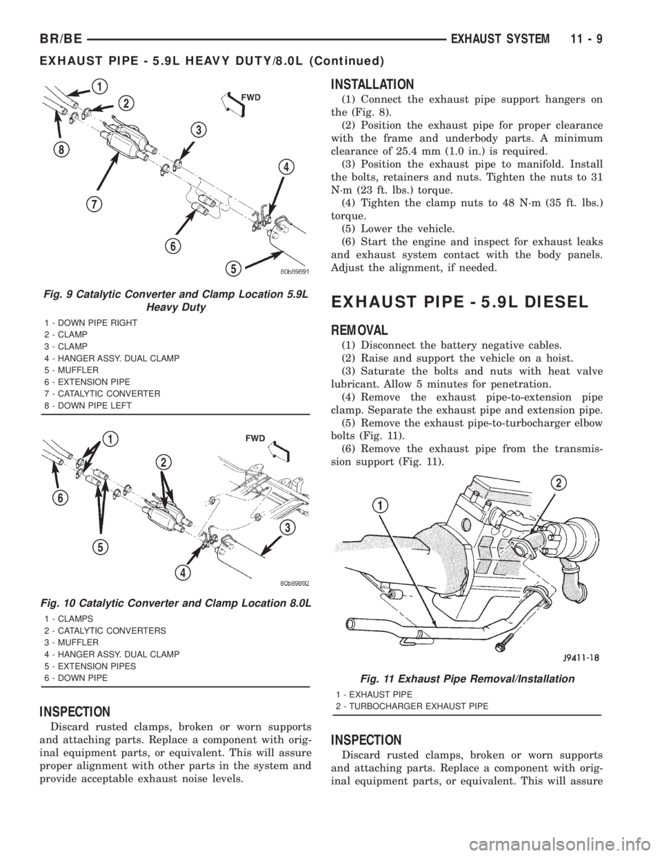
the (Fig. 8).
(2) Position the exhaust pipe for proper clearance
with the frame and underbody parts. A minimum
clearance of 25.4 mm (1.0 in.) is required.
(3) Position the exhaust pipe to manifold. Install
the bolts, retainers and nuts. Tighten the nuts to 31
N´m (23 ft. lbs.) torque.
(4) Tighten the clamp nuts to 48 N´m (35 ft. lbs.)
torque.
(5) Lower the vehicle.
(6) Start the engine and inspect for exhaust leaks
and exhaust system contact with the body panels.
Adjust the alignment, if needed.
EXHAUST PIPE - 5.9L DIESEL
REMOVAL
(1) Disconnect the battery negative cables.
(2) Raise and support the vehicle on a hoist.
(3) Saturate the bolts and nuts with heat valve
lubricant. Allow 5 minutes for penetration.
(4) Remove the exhaust pipe-to-extension pipe
clamp. Separate the exhaust pipe and extension pipe.
(5) Remove the exhaust pipe-to-turbocharger elbow
bolts (Fig. 11).
(6) Remove the exhaust pipe from the transmis-
sion support (Fig. 11).
INSPECTION
Discard rusted clamps, broken or worn supports
and attaching parts. Replace a component with orig-
inal equipment parts, or equivalent. This will assure
Fig. 9 Catalytic Converter and Clamp Location 5.9L
Heavy Duty
1 - DOWN PIPE RIGHT
2 - CLAMP
3 - CLAMP
4 - HANGER ASSY. DUAL CLAMP
5 - MUFFLER
6 - EXTENSION PIPE
7 - CATALYTIC CONVERTER
8 - DOWN PIPE LEFT
Fig. 10 Catalytic Converter and Clamp Location 8.0L
1 - CLAMPS
2 - CATALYTIC CONVERTERS
3 - MUFFLER
4 - HANGER ASSY. DUAL CLAMP
5 - EXTENSION PIPES
6 - DOWN PIPE
Fig. 11 Exhaust Pipe Removal/Installation
1 - EXHAUST PIPE
2 - TURBOCHARGER EXHAUST PIPE
BR/BEEXHAUST SYSTEM 11 - 9
EXHAUST PIPE - 5.9L HEAVY DUTY/8.0L (Continued)
Page 1490 of 2889
(4) Connect the 0-414 kPa (0-60 psi) fuel pressure
test gauge (from Gauge Set 5069) to the test port on
the appropriate Adaptor Tool.The DRBtIII Scan
Tool along with the PEP module, the 500 psi
pressure transducer, and the transducer-to-test
port adapter may also be used in place of the
fuel pressure gauge.
The fittings on both tools must be in good
condition and free from any small leaks before
performing the proceeding test.
(5) Start engine and bring to normal operating
temperature.
(6) Observe test gauge. Normal operating pressure
should be 339 kPa +/±34 kPa (49.2 psi +/±5 psi).
(7) Shut engine off.
(8) Pressure should not fall below30 psi for five
minutes.
(9) If pressure falls below 30 psi, it must be deter-
mined if a fuel injector, the check valve within the
fuel pump module, or a fuel tube/line is leaking.
(10) Again, start engine and bring to normal oper-
ating temperature.
(11) Shut engine off.
(12)Testing for fuel injector or fuel rail leak-
age:Clamp off the rubber hose portion of Adaptor
Tool between the fuel rail and the test port ªTº on
Adapter Tool. If pressure now holds at or above 30
psi, a fuel injector or the fuel rail is leaking.
(13)Testing for fuel pump check valve, filter/
regulator check valve or fuel tube/line leakage:
Clamp off the rubber hose portion of Adaptor Tool
between the vehicle fuel line and test port ªTº on
Adapter Tool. If pressure now holds at or above 30
psi, a leak may be found at a fuel tube/line. If no
leaks are found at fuel tubes or lines, one of the
check valves in either the electric fuel pump or filter/
regulator may be leaking.
Note: A quick loss of pressure usually indicates a
defective check valve in the filter/regulator. A slow
loss of pressure usually indicates a defective check
valve in the electric fuel pump.
The electric fuel pump is not serviced separately.
Replace the fuel pump module assembly. The filter/
regulator may be replaced separately on certain
applications. Refer to Fuel Filter/Fuel Pressure Reg-
ulator Removal/Installation for additional informa-
tion.STANDARD PROCEDURE - FUEL SYSTEM
PRESSURE RELEASE
Use following procedure if the fuel injector
rail is, or is not equipped with a fuel pressure
test port.
(1) Remove fuel fill cap.
(2) Remove fuel pump relay from Power Distribu-
tion Center (PDC). For location of relay, refer to label
on underside of PDC cover.
(3) Start and run engine until it stalls.
(4) Attempt restarting engine until it will no
longer run.
(5) Turn ignition key to OFF position.
CAUTION: Steps 1, 2, 3 and 4 must be performed to
relieve high pressure fuel from within fuel rail. Do
not attempt to use following steps to relieve this
pressure as excessive fuel will be forced into a cyl-
inder chamber.
(6) Unplug connector from any fuel injector.
(7) Attach one end of a jumper wire with alligator
clips (18 gauge or smaller) to either injector terminal.
(8) Connect other end of jumper wire to positive
side of battery.
(9) Connect one end of a second jumper wire to
remaining injector terminal.
CAUTION: Powering an injector for more than a few
seconds will permanently damage the injector.
(10) Momentarily touch other end of jumper wire
to negative terminal of battery for no more than a
few seconds.
(11) Place a rag or towel below fuel line quick-con-
nect fitting at fuel rail.
(12) Disconnect quick-connect fitting at fuel rail.
Refer to Quick-Connect Fittings.
(13) Return fuel pump relay to PDC.
(14) One or more Diagnostic Trouble Codes (DTC's)
may have been stored in PCM memory due to fuel
pump relay removal. The DRBtscan tool must be
used to erase a DTC.
BR/BEFUEL DELIVERY - GASOLINE 14 - 3
FUEL DELIVERY - GASOLINE (Continued)
Page 1498 of 2889
(1) Be sure fuel tank contains fuel before starting
test. If tank is empty or near empty, amperage read-
ings will be incorrect.
(2) Obtain LCS adapter.
(3) Plug cable from LCS adapter into DRB scan
tool at SET 1 receptacle.
(4) Plug DRB into vehicle 16±way connector (data
link connector).
(5) Connect (-) and (+) test cable leads into LCS
adapter receptacles. Use10 amp (10A +)receptacle
and common (-) receptacles.
(6) Gain access to MAIN MENU on DRB screen.
(7) Press DVOM button on DRB.
(8) Using left/right arrow keys, highlight CHAN-
NEL 1 function on DRB screen.
(9) Press ENTER three times.
(10) Using up/down arrow keys, highlight RANGE
on DRB screen (screen will default to 2 amp scale).
(11) Press ENTER to change 2 amp scale to 10
amp scale.This step must be done to prevent
damage to DRB scan tool or LCS adapter
(blown fuse).
(12) Remove cover from Power Distribution Center
(PDC).
(13) Remove fuel pump relay from PDC. Refer to
label on PDC cover for relay location.
WARNING: BEFORE PROCEEDING TO NEXT STEP,
NOTE THE FUEL PUMP WILL BE ACTIVATED AND
SYSTEM PRESSURE WILL BE PRESENT. THIS WILL
OCCUR AFTER CONNECTING TEST LEADS FROM
LCS ADAPTER INTO FUEL PUMP RELAY CAVITIES.
THE FUEL PUMP WILL OPERATE EVEN WITH IGNI-
TION KEY IN OFF POSITION. BEFORE ATTACHING
TEST LEADS, BE SURE ALL FUEL LINES AND
FUEL SYSTEM COMPONENTS ARE CONNECTED.
CAUTION: To prevent possible damage to the vehi-
cle electrical system and LCS adapter, the test
leads must be connected into relay cavities exactly
as shown in following steps.
Depending upon vehicle model, year or engine con-
figuration, three different types of relays may be
used: Type-1, type-2 and type±3.
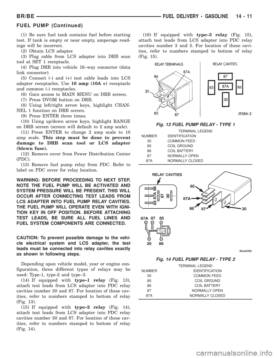
(14) If equipped withtype±1 relay(Fig. 13),
attach test leads from LCS adapter into PDC relay
cavities number 30 and 87. For location of these cav-
ities, refer to numbers stamped to bottom of relay
(Fig. 13).
(15) If equipped withtype±2 relay(Fig. 14),
attach test leads from LCS adapter into PDC relay
cavities number 30 and 87. For location of these cav-
ities, refer to numbers stamped to bottom of relay
(Fig. 14).(16) If equipped withtype±3 relay(Fig. 15),
attach test leads from LCS adapter into PDC relay
cavities number 3 and 5. For location of these cavi-
ties, refer to numbers stamped to bottom of relay
(Fig. 15).
Fig. 13 FUEL PUMP RELAY - TYPE 1
TERMINAL LEGEND
NUMBER IDENTIFICATION
30 COMMON FEED
85 COIL GROUND
86 COIL BATTERY
87 NORMALLY OPEN
87A NORMALLY CLOSED
Fig. 14 FUEL PUMP RELAY - TYPE 2
TERMINAL LEGEND
NUMBER IDENTIFICATION
30 COMMON FEED
85 COIL GROUND
86 COIL BATTERY
87 NORMALLY OPEN
87A NORMALLY CLOSED
BR/BEFUEL DELIVERY - GASOLINE 14 - 11
FUEL PUMP (Continued)
Page 1503 of 2889
A fuel pressure test port is located on the fuel rail.
A quick-connect fitting with a safety latch clip is
used to attach the fuel line to the fuel rail.
The fuel rail is not repairable.
REMOVAL - 3.9L/5.2L/5.9L
WARNING: THE FUEL SYSTEM IS UNDER A CON-
STANT PRESSURE (EVEN WITH ENGINE TURNED
OFF). BEFORE SERVICING FUEL RAIL ASSEMBLY,
FUEL SYSTEM PRESSURE MUST BE RELEASED.
To release fuel pressure, refer to Fuel System Pres-
sure Release Procedure found in this group.
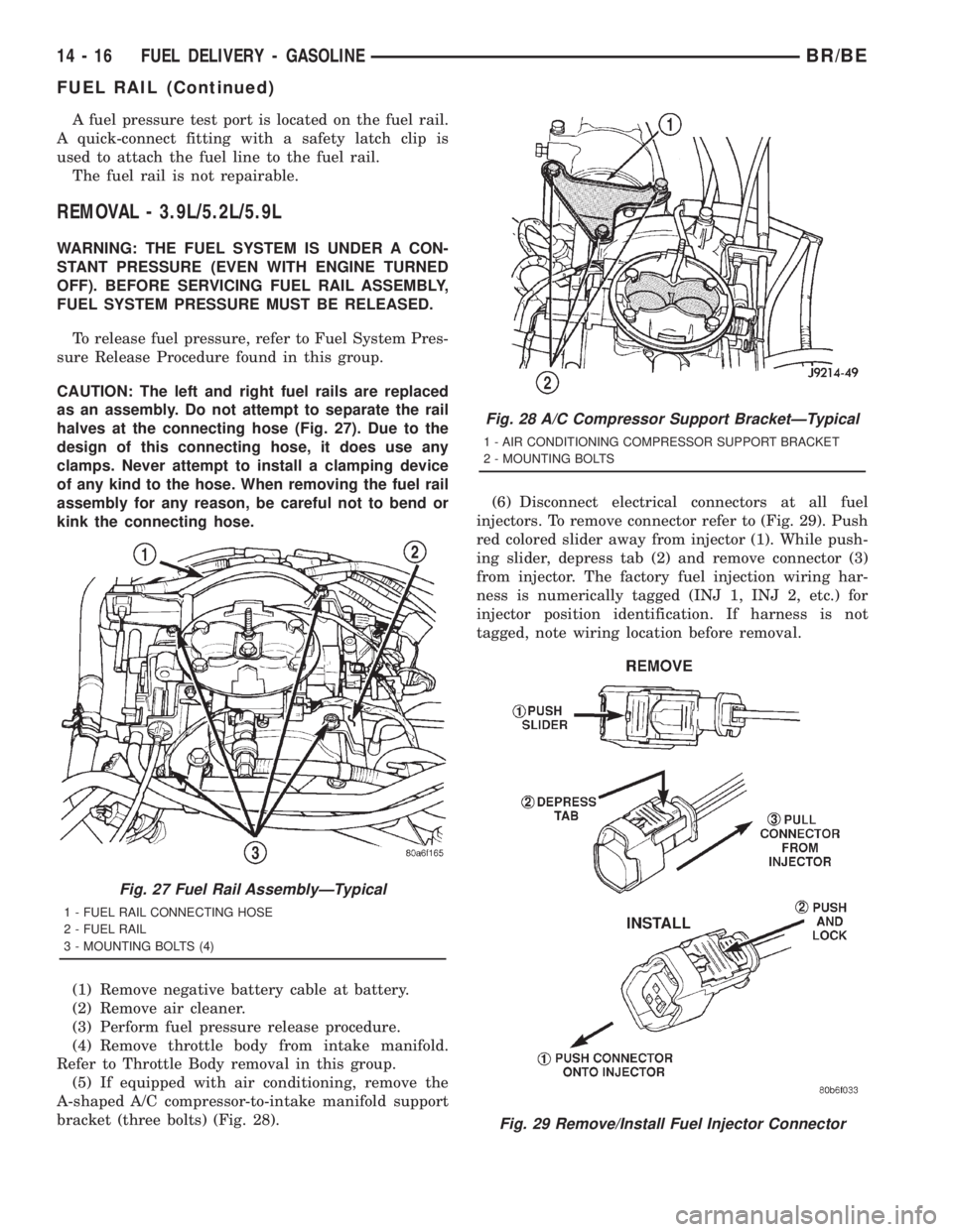
CAUTION: The left and right fuel rails are replaced
as an assembly. Do not attempt to separate the rail
halves at the connecting hose (Fig. 27). Due to the
design of this connecting hose, it does use any
clamps. Never attempt to install a clamping device
of any kind to the hose. When removing the fuel rail
assembly for any reason, be careful not to bend or
kink the connecting hose.
(1) Remove negative battery cable at battery.
(2) Remove air cleaner.
(3) Perform fuel pressure release procedure.
(4) Remove throttle body from intake manifold.
Refer to Throttle Body removal in this group.
(5) If equipped with air conditioning, remove the
A-shaped A/C compressor-to-intake manifold support
bracket (three bolts) (Fig. 28).(6) Disconnect electrical connectors at all fuel
injectors. To remove connector refer to (Fig. 29). Push
red colored slider away from injector (1). While push-
ing slider, depress tab (2) and remove connector (3)
from injector. The factory fuel injection wiring har-
ness is numerically tagged (INJ 1, INJ 2, etc.) for
injector position identification. If harness is not
tagged, note wiring location before removal.
Fig. 27 Fuel Rail AssemblyÐTypical
1 - FUEL RAIL CONNECTING HOSE
2 - FUEL RAIL
3 - MOUNTING BOLTS (4)
Fig. 28 A/C Compressor Support BracketÐTypical
1 - AIR CONDITIONING COMPRESSOR SUPPORT BRACKET
2 - MOUNTING BOLTS
Fig. 29 Remove/Install Fuel Injector Connector
14 - 16 FUEL DELIVERY - GASOLINEBR/BE
FUEL RAIL (Continued)
Page 1512 of 2889
(b) Type 2: Separate and unlatch 2 small arms
on end of clip (Fig. 47) and swing away from fuel
line.
(c) Slide latch clip toward fuel rail while lifting
with screwdriver.
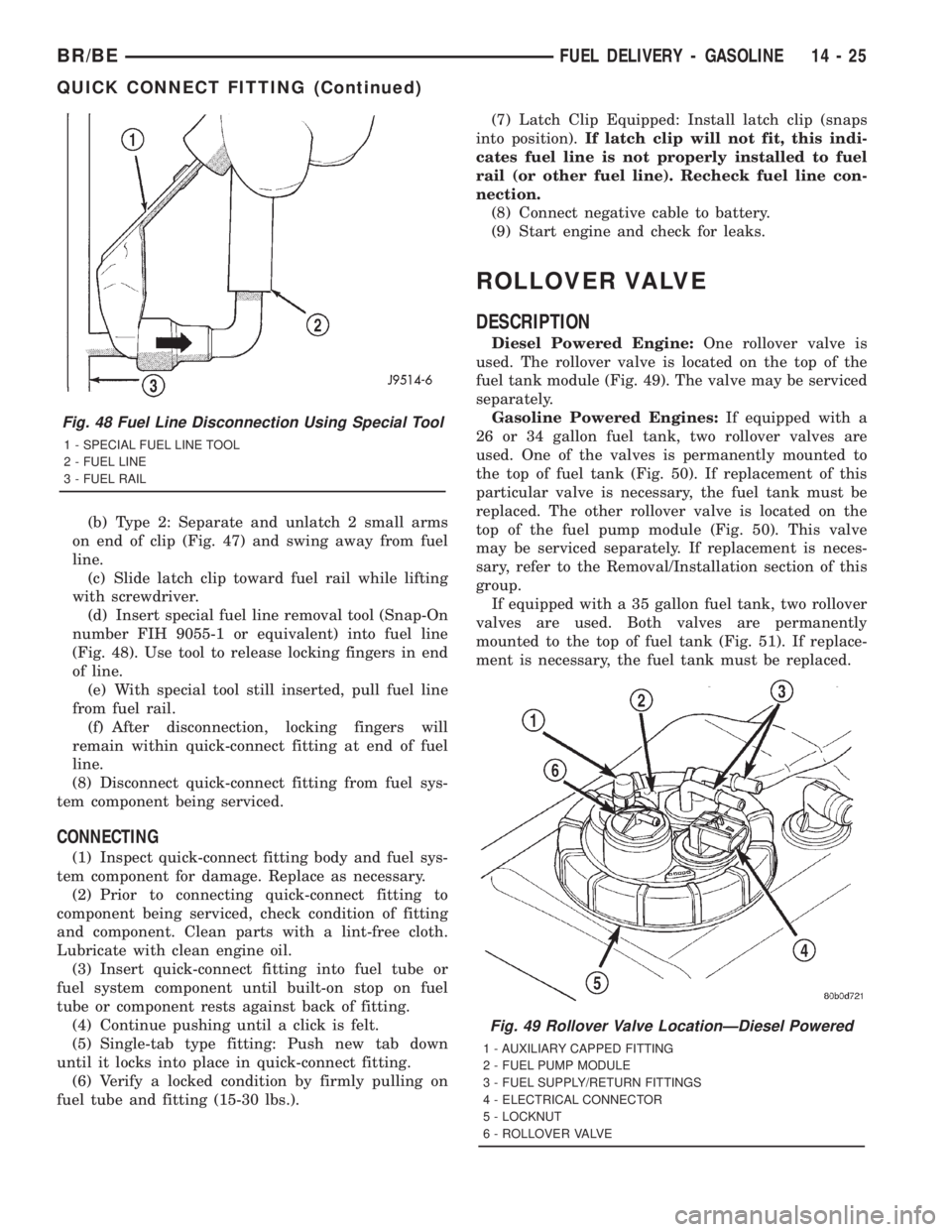
(d) Insert special fuel line removal tool (Snap-On
number FIH 9055-1 or equivalent) into fuel line
(Fig. 48). Use tool to release locking fingers in end
of line.
(e) With special tool still inserted, pull fuel line
from fuel rail.
(f) After disconnection, locking fingers will
remain within quick-connect fitting at end of fuel
line.
(8) Disconnect quick-connect fitting from fuel sys-
tem component being serviced.
CONNECTING
(1) Inspect quick-connect fitting body and fuel sys-
tem component for damage. Replace as necessary.
(2) Prior to connecting quick-connect fitting to
component being serviced, check condition of fitting
and component. Clean parts with a lint-free cloth.
Lubricate with clean engine oil.
(3) Insert quick-connect fitting into fuel tube or
fuel system component until built-on stop on fuel
tube or component rests against back of fitting.
(4) Continue pushing until a click is felt.
(5) Single-tab type fitting: Push new tab down
until it locks into place in quick-connect fitting.
(6) Verify a locked condition by firmly pulling on
fuel tube and fitting (15-30 lbs.).(7) Latch Clip Equipped: Install latch clip (snaps
into position).If latch clip will not fit, this indi-
cates fuel line is not properly installed to fuel
rail (or other fuel line). Recheck fuel line con-
nection.
(8) Connect negative cable to battery.
(9) Start engine and check for leaks.
ROLLOVER VALVE
DESCRIPTION
Diesel Powered Engine:One rollover valve is
used. The rollover valve is located on the top of the
fuel tank module (Fig. 49). The valve may be serviced
separately.
Gasoline Powered Engines:If equipped with a
26 or 34 gallon fuel tank, two rollover valves are
used. One of the valves is permanently mounted to
the top of fuel tank (Fig. 50). If replacement of this
particular valve is necessary, the fuel tank must be
replaced. The other rollover valve is located on the
top of the fuel pump module (Fig. 50). This valve
may be serviced separately. If replacement is neces-
sary, refer to the Removal/Installation section of this
group.
If equipped with a 35 gallon fuel tank, two rollover
valves are used. Both valves are permanently
mounted to the top of fuel tank (Fig. 51). If replace-
ment is necessary, the fuel tank must be replaced.
Fig. 48 Fuel Line Disconnection Using Special Tool
1 - SPECIAL FUEL LINE TOOL
2 - FUEL LINE
3 - FUEL RAIL
Fig. 49 Rollover Valve LocationÐDiesel Powered
1 - AUXILIARY CAPPED FITTING
2 - FUEL PUMP MODULE
3 - FUEL SUPPLY/RETURN FITTINGS
4 - ELECTRICAL CONNECTOR
5 - LOCKNUT
6 - ROLLOVER VALVE
BR/BEFUEL DELIVERY - GASOLINE 14 - 25
QUICK CONNECT FITTING (Continued)
Page 1513 of 2889
REMOVAL
WARNING: THE FUEL SYSTEM IS UNDER A CON-
STANT PRESSURE (EVEN WITH THE ENGINE OFF).
BEFORE SERVICING THE ROLLOVER VALVE, FUEL
SYSTEM PRESSURE MUST BE RELEASED (GASO-
LINE POWERED ENGINES ONLY). REFER TO THE
FUEL PRESSURE RELEASE PROCEDURE IN
GROUP 14, FUEL SYSTEM.
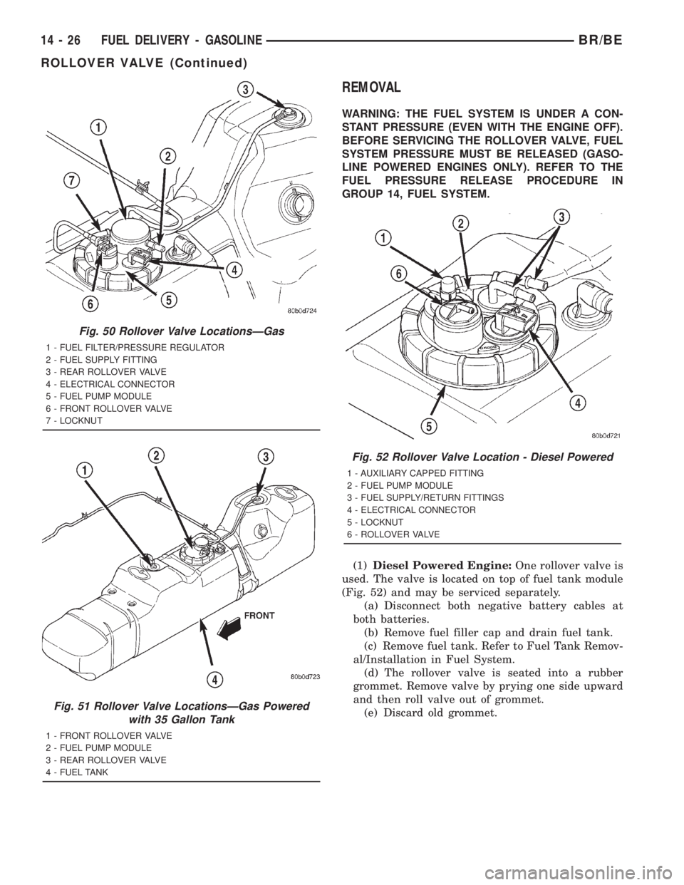
(1)Diesel Powered Engine:One rollover valve is
used. The valve is located on top of fuel tank module
(Fig. 52) and may be serviced separately.
(a) Disconnect both negative battery cables at
both batteries.
(b) Remove fuel filler cap and drain fuel tank.
(c) Remove fuel tank. Refer to Fuel Tank Remov-
al/Installation in Fuel System.
(d) The rollover valve is seated into a rubber
grommet. Remove valve by prying one side upward
and then roll valve out of grommet.
(e) Discard old grommet.
Fig. 50 Rollover Valve LocationsÐGas
1 - FUEL FILTER/PRESSURE REGULATOR
2 - FUEL SUPPLY FITTING
3 - REAR ROLLOVER VALVE
4 - ELECTRICAL CONNECTOR
5 - FUEL PUMP MODULE
6 - FRONT ROLLOVER VALVE
7 - LOCKNUT
Fig. 51 Rollover Valve LocationsÐGas Powered
with 35 Gallon Tank
1 - FRONT ROLLOVER VALVE
2 - FUEL PUMP MODULE
3 - REAR ROLLOVER VALVE
4 - FUEL TANK
Fig. 52 Rollover Valve Location - Diesel Powered
1 - AUXILIARY CAPPED FITTING
2 - FUEL PUMP MODULE
3 - FUEL SUPPLY/RETURN FITTINGS
4 - ELECTRICAL CONNECTOR
5 - LOCKNUT
6 - ROLLOVER VALVE
14 - 26 FUEL DELIVERY - GASOLINEBR/BE
ROLLOVER VALVE (Continued)
Page 1514 of 2889
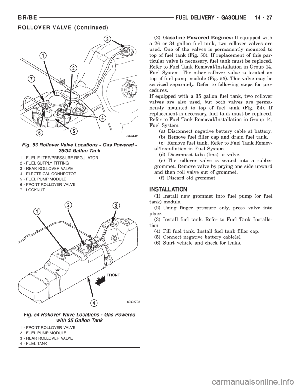
(2)Gasoline Powered Engines:If equipped with
a 26 or 34 gallon fuel tank, two rollover valves are
used. One of the valves is permanently mounted to
top of fuel tank (Fig. 53). If replacement of this par-
ticular valve is necessary, fuel tank must be replaced.
Refer to Fuel Tank Removal/Installation in Group 14,
Fuel System. The other rollover valve is located on
top of fuel pump module (Fig. 53). This valve may be
serviced separately. Refer to following steps for pro-
cedures.
If equipped with a 35 gallon fuel tank, two rollover
valves are also used, but both valves are perma-
nently mounted to top of fuel tank (Fig. 54). If
replacement is necessary, fuel tank must be replaced.
Refer to Fuel Tank Removal/Installation in Group 14,
Fuel System.
(a) Disconnect negative battery cable at battery.
(b) Remove fuel filler cap and drain fuel tank.
(c) Remove fuel tank. Refer to Fuel Tank Remov-
al/Installation in Fuel System.
(d) Disconnect tube (line) at valve.
(e) The rollover valve is seated into a rubber
grommet. Remove valve by prying one side upward
and then roll valve out of grommet.
(f) Discard old grommet.
INSTALLATION
(1) Install new grommet into fuel pump (or fuel
tank) module.
(2) Using finger pressure only, press valve into
place.
(3) Install fuel tank. Refer to Fuel Tank Installa-
tion.
(4) Fill fuel tank. Install fuel tank filler cap.
(5) Connect negative battery cable(s).
(6) Start vehicle and check for leaks.
Fig. 53 Rollover Valve Locations - Gas Powered -
26/34 Gallon Tank
1 - FUEL FILTER/PRESSURE REGULATOR
2 - FUEL SUPPLY FITTING
3 - REAR ROLLOVER VALVE
4 - ELECTRICAL CONNECTOR
5 - FUEL PUMP MODULE
6 - FRONT ROLLOVER VALVE
7 - LOCKNUT
Fig. 54 Rollover Valve Locations - Gas Powered
with 35 Gallon Tank
1 - FRONT ROLLOVER VALVE
2 - FUEL PUMP MODULE
3 - REAR ROLLOVER VALVE
4 - FUEL TANK
BR/BEFUEL DELIVERY - GASOLINE 14 - 27
ROLLOVER VALVE (Continued)
Page 1515 of 2889
FUEL INJECTION - GASOLINE
TABLE OF CONTENTS
page page
FUEL INJECTION - GASOLINE
DIAGNOSIS AND TESTING.................28
VISUAL INSPECTION - 3.9L/5.2L/5.9L
ENGINES.............................28
VISUAL INSPECTION - 8.0L ENGINE........32
SPECIFICATIONS........................35
SPECIAL TOOLS.........................36
ACCELERATOR PEDAL
REMOVAL..............................37
INSTALLATION...........................37
CRANKSHAFT POSITION SENSOR
DESCRIPTION...........................38
OPERATION.............................38
REMOVAL..............................39
INSTALLATION...........................40
FUEL PUMP RELAY
DESCRIPTION...........................41
OPERATION.............................41
REMOVAL..............................41
INSTALLATION...........................41
IDLE AIR CONTROL MOTOR
DESCRIPTION...........................41
OPERATION.............................41
REMOVAL..............................42
INSTALLATION...........................42
INTAKE AIR TEMPERATURE SENSOR
DESCRIPTION...........................43
OPERATION.............................43
REMOVAL..............................43
INSTALLATION...........................43
MANIFOLD ABSOLUTE PRESSURE SENSOR
DESCRIPTION...........................44OPERATION.............................44
REMOVAL..............................45
INSTALLATION...........................45
O2 SENSOR
DESCRIPTION...........................46
OPERATION.............................46
REMOVAL..............................47
INSTALLATION...........................48
PTO SWITCH
DESCRIPTION...........................48
OPERATION.............................48
THROTTLE BODY
DESCRIPTION...........................48
OPERATION.............................48
REMOVAL..............................48
INSTALLATION...........................49
THROTTLE CONTROL CABLE
REMOVAL..............................50
INSTALLATION...........................50
THROTTLE POSITION SENSOR
DESCRIPTION...........................51
OPERATION.............................51
REMOVAL..............................51
INSTALLATION...........................52
FUEL INJECTOR
DESCRIPTION...........................53
OPERATION.............................53
DIAGNOSIS AND TESTING.................53
FUEL INJECTOR TEST...................53
REMOVAL..............................53
INSTALLATION...........................53
FUEL INJECTION - GASOLINE
VISUAL INSPECTIONÐ3.9L/5.2L/5.9L
ENGINES
A visual inspection for loose, disconnected or incor-
rectly routed wires and hoses should be made. This
should be done before attempting to diagnose or ser-
vice the fuel injection system. A visual check will
help spot these faults and save unnecessary test and
diagnostic time. A thorough visual inspection will
include the following checks:
(1) Verify that the three 32±way electrical connec-
tors are fully inserted into the connector of the pow-
ertrain control module (PCM) (Fig. 1).(2) Inspect the battery cable connections. Be sure
that they are clean and tight.
(3) Inspect fuel pump relay and air conditioning
compressor clutch relay (if equipped). Inspect the
ASD relay connections. Inspect starter motor relay
connections. Inspect relays for signs of physical dam-
age and corrosion. The relays are located in the
Power Distribution Center (PDC) (Fig. 2). Refer to
label on PDC cover for relay location.
(4) Inspect ignition coil connections. Verify that
coil secondary cable is firmly connected to coil (Fig.
3).
14 - 28 FUEL INJECTION - GASOLINEBR/BE