2001 DODGE RAM fuel filter
[x] Cancel search: fuel filterPage 1586 of 2889
(g) If any of these conditions occur, replace injec-
tor.
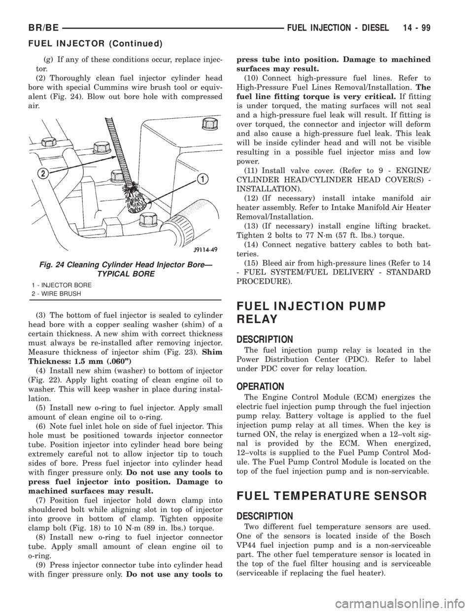
(2) Thoroughly clean fuel injector cylinder head
bore with special Cummins wire brush tool or equiv-
alent (Fig. 24). Blow out bore hole with compressed
air.
(3) The bottom of fuel injector is sealed to cylinder
head bore with a copper sealing washer (shim) of a
certain thickness. A new shim with correct thickness
must always be re-installed after removing injector.
Measure thickness of injector shim (Fig. 23).Shim
Thickness: 1.5 mm (.060º)
(4) Install new shim (washer) to bottom of injector
(Fig. 22). Apply light coating of clean engine oil to
washer. This will keep washer in place during instal-
lation.
(5) Install new o-ring to fuel injector. Apply small
amount of clean engine oil to o-ring.
(6) Note fuel inlet hole on side of fuel injector. This
hole must be positioned towards injector connector
tube. Position injector into cylinder head bore being
extremely careful not to allow injector tip to touch
sides of bore. Press fuel injector into cylinder head
with finger pressure only.Do not use any tools to
press fuel injector into position. Damage to
machined surfaces may result.
(7) Position fuel injector hold down clamp into
shouldered bolt while aligning slot in top of injector
into groove in bottom of clamp. Tighten opposite
clamp bolt (Fig. 18) to 10 N´m (89 in. lbs.) torque.
(8) Install new o-ring to fuel injector connector
tube. Apply small amount of clean engine oil to
o-ring.
(9) Press injector connector tube into cylinder head
with finger pressure only.Do not use any tools topress tube into position. Damage to machined
surfaces may result.
(10) Connect high-pressure fuel lines. Refer to
High-Pressure Fuel Lines Removal/Installation.The
fuel line fitting torque is very critical.If fitting
is under torqued, the mating surfaces will not seal
and a high-pressure fuel leak will result. If fitting is
over torqued, the connector and injector will deform
and also cause a high-pressure fuel leak. This leak
will be inside cylinder head and will not be visible
resulting in a possible fuel injector miss and low
power.
(11) Install valve cover. (Refer to 9 - ENGINE/
CYLINDER HEAD/CYLINDER HEAD COVER(S) -
INSTALLATION).
(12) (If necessary) install intake manifold air
heater assembly. Refer to Intake Manifold Air Heater
Removal/Installation.
(13) (If necessary) install engine lifting bracket.
Tighten 2 bolts to 77 N´m (57 ft. lbs.) torque.
(14) Connect negative battery cables to both bat-
teries.
(15) Bleed air from high-pressure lines (Refer to 14
- FUEL SYSTEM/FUEL DELIVERY - STANDARD
PROCEDURE).
FUEL INJECTION PUMP
RELAY
DESCRIPTION
The fuel injection pump relay is located in the
Power Distribution Center (PDC). Refer to label
under PDC cover for relay location.
OPERATION
The Engine Control Module (ECM) energizes the
electric fuel injection pump through the fuel injection
pump relay. Battery voltage is applied to the fuel
injection pump relay at all times. When the key is
turned ON, the relay is energized when a 12±volt sig-
nal is provided by the ECM. When energized,
12±volts is supplied to the Fuel Pump Control Mod-
ule. The Fuel Pump Control Module is located on the
top of the fuel injection pump and is non-servicable.
FUEL TEMPERATURE SENSOR
DESCRIPTION
Two different fuel temperature sensors are used.
One of the sensors is located inside of the Bosch
VP44 fuel injection pump and is a non-serviceable
part. The other fuel temperature sensor is located in
the top of the fuel filter housing and is serviceable
(serviceable if replacing the fuel heater).
Fig. 24 Cleaning Cylinder Head Injector BoreÐ
TYPICAL BORE
1 - INJECTOR BORE
2 - WIRE BRUSH
BR/BEFUEL INJECTION - DIESEL 14 - 99
FUEL INJECTOR (Continued)
Page 1587 of 2889
OPERATION
The sensor located in the Bosch VP44 fuel injection
pump is used to check fuel temperature within the
injection pump and to set a Diagnostic Trouble Code
(DTC) if a specific high fuel temperature has been
reached. If high temperature has been reached,
engine power will be de-rated by the Engine Control
Module (ECM).
The sensor located in the top of the fuel filter hous-
ing is used to control the fuel heater element. Refer
to Fuel Heater Description and Operation for addi-
tional information.
INTAKE AIR HEATER
DESCRIPTION
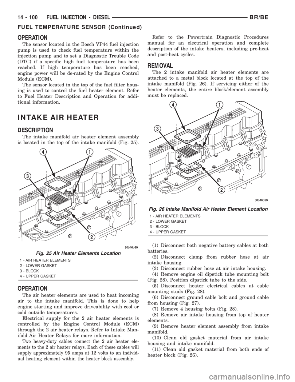
The intake manifold air heater element assembly
is located in the top of the intake manifold (Fig. 25).
OPERATION
The air heater elements are used to heat incoming
air to the intake manifold. This is done to help
engine starting and improve driveability with cool or
cold outside temperatures.
Electrical supply for the 2 air heater elements is
controlled by the Engine Control Module (ECM)
through the 2 air heater relays. Refer to Intake Man-
ifold Air Heater Relays for more information.
Two heavy-duty cables connect the 2 air heater ele-
ments to the 2 air heater relays. Each of these cables will
supply approximately 95 amps at 12 volts to an individ-
ual heating element within the heater block assembly.
Refer to the Powertrain Diagnostic Procedures
manual for an electrical operation and complete
description of the intake heaters, including pre-heat
and post-heat cycles.
REMOVAL
The 2 intake manifold air heater elements are
attached to a metal block located at the top of the
intake manifold (Fig. 26). If servicing either of the
heater elements, the entire block/element assembly
must be replaced.
(1) Disconnect both negative battery cables at both
batteries.
(2) Disconnect clamp from rubber hose at air
intake housing.
(3) Disconnect rubber hose at air intake housing.
(4) Remove engine oil dipstick tube mounting bolt
(Fig. 28). Position dipstick tube to the side.
(5) Disconnect heater electrical cables at cable
mounting studs (Fig. 28).
(6) Disconnect ground cable bolt and ground cable
from housing (Fig. 27).
(7) Remove 4 housing bolts (Fig. 28).
(8) Remove air intake housing from top of heater
elements.
(9) Remove heater element assembly from intake
manifold.
(10) Clean old gasket material from air intake
housing and intake manifold.
(11) Clean old gasket material from both ends of
heater block (Fig. 26).
Fig. 25 Air Heater Elements Location
1 - AIR HEATER ELEMENTS
2 - LOWER GASKET
3 - BLOCK
4 - UPPER GASKET
Fig. 26 Intake Manifold Air Heater Element Location
1 - AIR HEATER ELEMENTS
2 - LOWER GASKET
3 - BLOCK
4 - UPPER GASKET
14 - 100 FUEL INJECTION - DIESELBR/BE
FUEL TEMPERATURE SENSOR (Continued)
Page 1772 of 2889
IDENTIFICATION
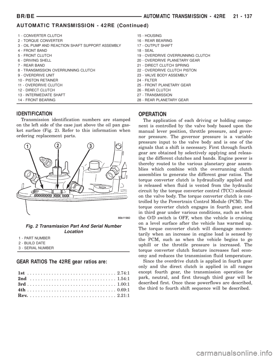
Transmission identification numbers are stamped
on the left side of the case just above the oil pan gas-
ket surface (Fig. 2). Refer to this information when
ordering replacement parts.
GEAR RATIOS The 42RE gear ratios are:
1st.................................2.74:1
2nd................................1.54:1
3rd.................................1.00:1
4th.................................0.69:1
Rev.................................2.21:1
OPERATION
The application of each driving or holding compo-
nent is controlled by the valve body based upon the
manual lever position, throttle pressure, and gover-
nor pressure. The governor pressure is a variable
pressure input to the valve body and is one of the
signals that a shift is necessary. First through fourth
gear are obtained by selectively applying and releas-
ing the different clutches and bands. Engine power is
thereby routed to the various planetary gear assem-
blies which combine with the overrunning clutch
assemblies to generate the different gear ratios. The
torque converter clutch is hydraulically applied and
is released when fluid is vented from the hydraulic
circuit by the torque converter control (TCC) solenoid
on the valve body. The torque converter clutch is con-
trolled by the Powertrain Control Module (PCM). The
torque converter clutch engages in fourth gear, and
in third gear under various conditions, such as when
the O/D switch is OFF, when the vehicle is cruising
on a level surface after the vehicle has warmed up.
The torque converter clutch will disengage momen-
tarily when an increase in engine load is sensed by
the PCM, such as when the vehicle begins to go
uphill or the throttle pressure is increased. The
torque converter clutch feature increases fuel econ-
omy and reduces the transmission fluid temperature.
Since the overdrive clutch is applied in fourth gear
only and the direct clutch is applied in all ranges
except fourth gear, the transmission operation for
park, neutral, and first through third gear will be
described first. Once these powerflows are described,
the third to fourth shift sequence will be described.
1 - CONVERTER CLUTCH 15 - HOUSING
2 - TORQUE CONVERTER 16 - REAR BEARING
3 - OIL PUMP AND REACTION SHAFT SUPPORT ASSEMBLY 17 - OUTPUT SHAFT
4 - FRONT BAND 18 - SEAL
5 - FRONT CLUTCH 19 - OVERDRIVE OVERRUNNING CLUTCH
6 - DRIVING SHELL 20 - OVERDRIVE PLANETARY GEAR
7 - REAR BAND 21 - DIRECT CLUTCH SPRING
8 - TRANSMISSION OVERRUNNING CLUTCH 22 - OVERDRIVE CLUTCH PISTON
9 - OVERDRIVE UNIT 23 - VALVE BODY ASSEMBLY
10 - PISTON RETAINER 24 - FILTER
11 - OVERDRIVE CLUTCH 25 - FRONT PLANETARY GEAR
12 - DIRECT CLUTCH 26 - REAR CLUTCH
13 - INTERMEDIATE SHAFT 27 - TRANSMISSION
14 - FRONT BEARING 28 - REAR PLANETARY GEAR
Fig. 2 Transmission Part And Serial Number
Location
1 - PART NUMBER
2 - BUILD DATE
3 - SERIAL NUMBER
BR/BEAUTOMATIC TRANSMISSION - 42RE 21 - 137
AUTOMATIC TRANSMISSION - 42RE (Continued)
Page 1943 of 2889
IDENTIFICATION
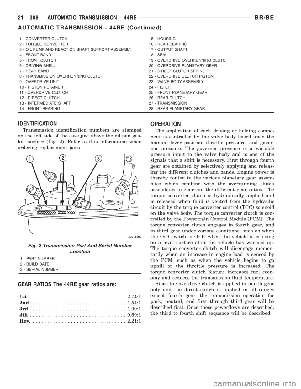
Transmission identification numbers are stamped
on the left side of the case just above the oil pan gas-
ket surface (Fig. 2). Refer to this information when
ordering replacement parts.
GEAR RATIOS The 44RE gear ratios are:
1st.................................2.74:1
2nd................................1.54:1
3rd.................................1.00:1
4th.................................0.69:1
Rev.................................2.21:1
OPERATION
The application of each driving or holding compo-
nent is controlled by the valve body based upon the
manual lever position, throttle pressure, and gover-
nor pressure. The governor pressure is a variable
pressure input to the valve body and is one of the
signals that a shift is necessary. First through fourth
gear are obtained by selectively applying and releas-
ing the different clutches and bands. Engine power is
thereby routed to the various planetary gear assem-
blies which combine with the overrunning clutch
assemblies to generate the different gear ratios. The
torque converter clutch is hydraulically applied and
is released when fluid is vented from the hydraulic
circuit by the torque converter control (TCC) solenoid
on the valve body. The torque converter clutch is con-
trolled by the Powertrain Control Module (PCM). The
torque converter clutch engages in fourth gear, and
in third gear under various conditions, such as when
the O/D switch is OFF, when the vehicle is cruising
on a level surface after the vehicle has warmed up.
The torque converter clutch will disengage momen-
tarily when an increase in engine load is sensed by
the PCM, such as when the vehicle begins to go
uphill or the throttle pressure is increased. The
torque converter clutch feature increases fuel econ-
omy and reduces the transmission fluid temperature.
Since the overdrive clutch is applied in fourth gear
only and the direct clutch is applied in all ranges
except fourth gear, the transmission operation for
park, neutral, and first through third gear will be
described first. Once these powerflows are described,
the third to fourth shift sequence will be described.
1 - CONVERTER CLUTCH 15 - HOUSING
2 - TORQUE CONVERTER 16 - REAR BEARING
3 - OIL PUMP AND REACTION SHAFT SUPPORT ASSEMBLY 17 - OUTPUT SHAFT
4 - FRONT BAND 18 - SEAL
5 - FRONT CLUTCH 19 - OVERDRIVE OVERRUNNING CLUTCH
6 - DRIVING SHELL 20 - OVERDRIVE PLANETARY GEAR
7 - REAR BAND 21 - DIRECT CLUTCH SPRING
8 - TRANSMISSION OVERRUNNING CLUTCH 22 - OVERDRIVE CLUTCH PISTON
9 - OVERDRIVE UNIT 23 - VALVE BODY ASSEMBLY
10 - PISTON RETAINER 24 - FILTER
11 - OVERDRIVE CLUTCH 25 - FRONT PLANETARY GEAR
12 - DIRECT CLUTCH 26 - REAR CLUTCH
13 - INTERMEDIATE SHAFT 27 - TRANSMISSION
14 - FRONT BEARING 28 - REAR PLANETARY GEAR
Fig. 2 Transmission Part And Serial Number
Location
1 - PART NUMBER
2 - BUILD DATE
3 - SERIAL NUMBER
21 - 308 AUTOMATIC TRANSMISSION - 44REBR/BE
AUTOMATIC TRANSMISSION - 44RE (Continued)
Page 2115 of 2889
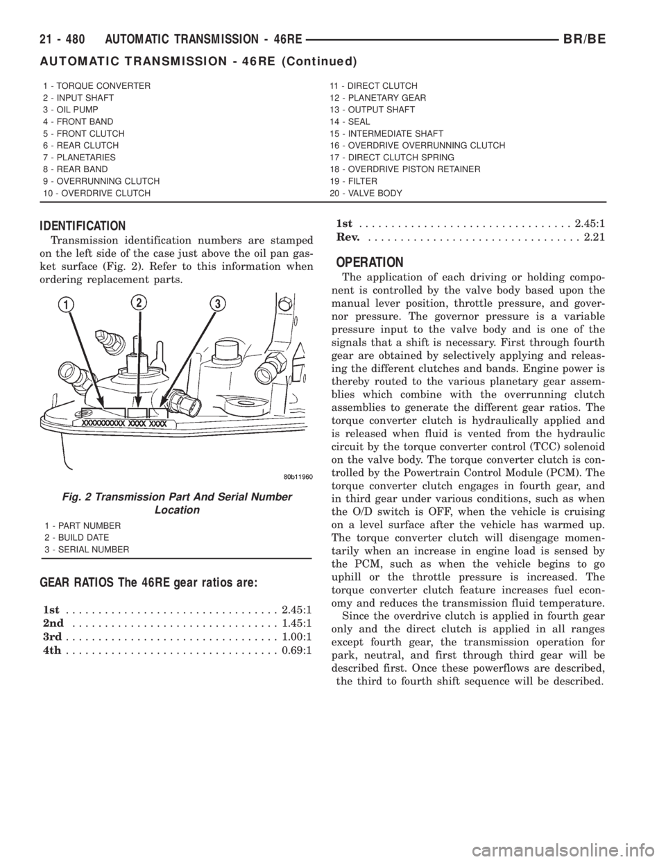
IDENTIFICATION
Transmission identification numbers are stamped
on the left side of the case just above the oil pan gas-
ket surface (Fig. 2). Refer to this information when
ordering replacement parts.
GEAR RATIOS The 46RE gear ratios are:
1st.................................2.45:1
2nd................................1.45:1
3rd.................................1.00:1
4th.................................0.69:11st.................................2.45:1
Rev..................................2.21
OPERATION
The application of each driving or holding compo-
nent is controlled by the valve body based upon the
manual lever position, throttle pressure, and gover-
nor pressure. The governor pressure is a variable
pressure input to the valve body and is one of the
signals that a shift is necessary. First through fourth
gear are obtained by selectively applying and releas-
ing the different clutches and bands. Engine power is
thereby routed to the various planetary gear assem-
blies which combine with the overrunning clutch
assemblies to generate the different gear ratios. The
torque converter clutch is hydraulically applied and
is released when fluid is vented from the hydraulic
circuit by the torque converter control (TCC) solenoid
on the valve body. The torque converter clutch is con-
trolled by the Powertrain Control Module (PCM). The
torque converter clutch engages in fourth gear, and
in third gear under various conditions, such as when
the O/D switch is OFF, when the vehicle is cruising
on a level surface after the vehicle has warmed up.
The torque converter clutch will disengage momen-
tarily when an increase in engine load is sensed by
the PCM, such as when the vehicle begins to go
uphill or the throttle pressure is increased. The
torque converter clutch feature increases fuel econ-
omy and reduces the transmission fluid temperature.
Since the overdrive clutch is applied in fourth gear
only and the direct clutch is applied in all ranges
except fourth gear, the transmission operation for
park, neutral, and first through third gear will be
described first. Once these powerflows are described,
the third to fourth shift sequence will be described.
1 - TORQUE CONVERTER 11 - DIRECT CLUTCH
2 - INPUT SHAFT 12 - PLANETARY GEAR
3 - OIL PUMP 13 - OUTPUT SHAFT
4 - FRONT BAND 14 - SEAL
5 - FRONT CLUTCH 15 - INTERMEDIATE SHAFT
6 - REAR CLUTCH 16 - OVERDRIVE OVERRUNNING CLUTCH
7 - PLANETARIES 17 - DIRECT CLUTCH SPRING
8 - REAR BAND 18 - OVERDRIVE PISTON RETAINER
9 - OVERRUNNING CLUTCH 19 - FILTER
10 - OVERDRIVE CLUTCH 20 - VALVE BODY
Fig. 2 Transmission Part And Serial Number
Location
1 - PART NUMBER
2 - BUILD DATE
3 - SERIAL NUMBER
21 - 480 AUTOMATIC TRANSMISSION - 46REBR/BE
AUTOMATIC TRANSMISSION - 46RE (Continued)
Page 2286 of 2889
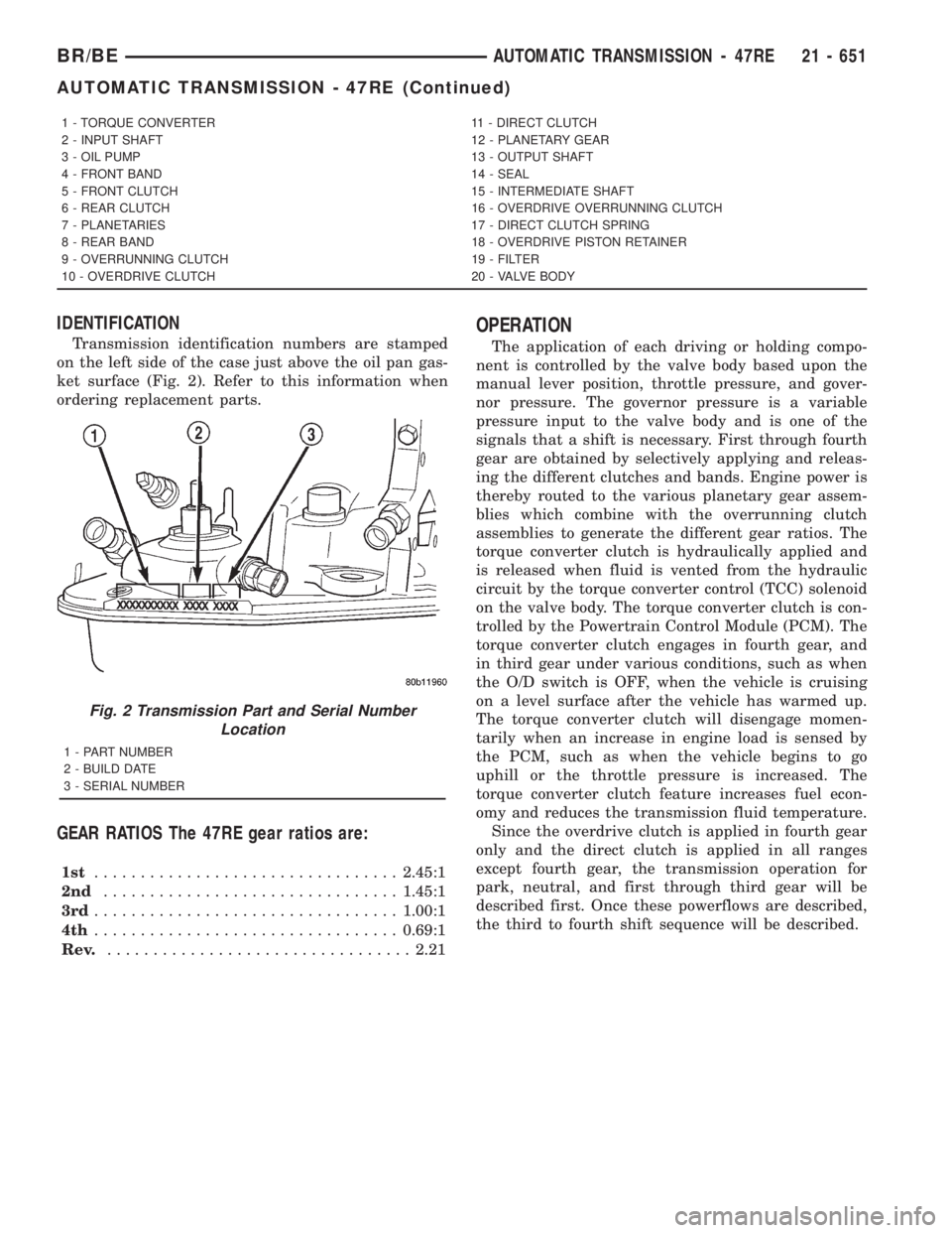
IDENTIFICATION
Transmission identification numbers are stamped
on the left side of the case just above the oil pan gas-
ket surface (Fig. 2). Refer to this information when
ordering replacement parts.
GEAR RATIOS The 47RE gear ratios are:
1st.................................2.45:1
2nd................................1.45:1
3rd.................................1.00:1
4th.................................0.69:1
Rev..................................2.21
OPERATION
The application of each driving or holding compo-
nent is controlled by the valve body based upon the
manual lever position, throttle pressure, and gover-
nor pressure. The governor pressure is a variable
pressure input to the valve body and is one of the
signals that a shift is necessary. First through fourth
gear are obtained by selectively applying and releas-
ing the different clutches and bands. Engine power is
thereby routed to the various planetary gear assem-
blies which combine with the overrunning clutch
assemblies to generate the different gear ratios. The
torque converter clutch is hydraulically applied and
is released when fluid is vented from the hydraulic
circuit by the torque converter control (TCC) solenoid
on the valve body. The torque converter clutch is con-
trolled by the Powertrain Control Module (PCM). The
torque converter clutch engages in fourth gear, and
in third gear under various conditions, such as when
the O/D switch is OFF, when the vehicle is cruising
on a level surface after the vehicle has warmed up.
The torque converter clutch will disengage momen-
tarily when an increase in engine load is sensed by
the PCM, such as when the vehicle begins to go
uphill or the throttle pressure is increased. The
torque converter clutch feature increases fuel econ-
omy and reduces the transmission fluid temperature.
Since the overdrive clutch is applied in fourth gear
only and the direct clutch is applied in all ranges
except fourth gear, the transmission operation for
park, neutral, and first through third gear will be
described first. Once these powerflows are described,
the third to fourth shift sequence will be described.
1 - TORQUE CONVERTER 11 - DIRECT CLUTCH
2 - INPUT SHAFT 12 - PLANETARY GEAR
3 - OIL PUMP 13 - OUTPUT SHAFT
4 - FRONT BAND 14 - SEAL
5 - FRONT CLUTCH 15 - INTERMEDIATE SHAFT
6 - REAR CLUTCH 16 - OVERDRIVE OVERRUNNING CLUTCH
7 - PLANETARIES 17 - DIRECT CLUTCH SPRING
8 - REAR BAND 18 - OVERDRIVE PISTON RETAINER
9 - OVERRUNNING CLUTCH 19 - FILTER
10 - OVERDRIVE CLUTCH 20 - VALVE BODY
Fig. 2 Transmission Part and Serial Number
Location
1 - PART NUMBER
2 - BUILD DATE
3 - SERIAL NUMBER
BR/BEAUTOMATIC TRANSMISSION - 47RE 21 - 651
AUTOMATIC TRANSMISSION - 47RE (Continued)
Page 2810 of 2889
FUEL PRESSURE
The fuel pressure regulator controls fuel system
pressure. The PCM cannot detect a clogged fuel
pump inlet filter, clogged in-line fuel filter, or a
pinched fuel supply or return line. However, these
could result in a rich or lean condition causing the
PCM to store an oxygen sensor or fuel system diag-
nostic trouble code.
SECONDARY IGNITION CIRCUIT
The PCM cannot detect an inoperative ignition coil,
fouled or worn spark plugs, ignition cross firing, or
open spark plug cables.
CYLINDER COMPRESSION
The PCM cannot detect uneven, low, or high engine
cylinder compression.
EXHAUST SYSTEM
The PCM cannot detect a plugged, restricted or
leaking exhaust system, although it may set a fuel
system fault.
FUEL INJECTOR MECHANICAL MALFUNCTIONS
The PCM cannot determine if a fuel injector is
clogged, the needle is sticking or if the wrong injector
is installed. However, these could result in a rich or
lean condition causing the PCM to store a diagnostic
trouble code for either misfire, an oxygen sensor, or
the fuel system.
EXCESSIVE OIL CONSUMPTION
Although the PCM monitors engine exhaust oxygen
content when the system is in closed loop, it cannot
determine excessive oil consumption.
THROTTLE BODY AIR FLOW
The PCM cannot detect a clogged or restricted air
cleaner inlet or filter element.
VACUUM ASSIST
The PCM cannot detect leaks or restrictions in the
vacuum circuits of vacuum assisted engine control
system devices. However, these could cause the PCM
to store a MAP sensor diagnostic trouble code and
cause a high idle condition.
PCM SYSTEM GROUND
The PCM cannot determine a poor system ground.
However, one or more diagnostic trouble codes may
be generated as a result of this condition. The mod-
ule should be mounted to the body at all times, also
during diagnostic.
PCM CONNECTOR ENGAGEMENT
The PCM may not be able to determine spread or
damaged connector pins. However, it might storediagnostic trouble codes as a result of spread connec-
tor pins.
OPERATION - NON-MONITORED CIRCUITS -
DIESEL
The PCM and/or the ECM will not monitor certain
malfunctioning circuits or components that could
cause driveability problems. Also, a Diagnostic Trou-
ble Code (DTC) might not be stored for these mal-
functions. However, problems with these circuits or
components may cause the PCM/ECM to store DTC's
for other circuits or components.EXAMPLES:A cyl-
inder with low compression will not set a DTC
directly, but may cause an engine misfire. This in
turn may cause the ECM to set a DTC for an engine
misfire. Or, a dirty or plugged air filter will not set a
DTC directly, but may cause lack of turbocharger
boost. This in turn may cause the ECM to set a DTC
for a boost pressure malfunction.
FUEL PRESSURE
Primary fuel pressure from the fuel tank to the
fuel injection pump is supplied by the low-pressure
fuel transfer pump. High-pressure to the fuel injec-
tors is supplied by the fuel injection pump. The ECM
cannot detect actual fuel pressure, a clogged fuel fil-
ter, clogged fuel screen, or a pinched fuel supply or
return line. However, a DTC may be set due to an
engine misfire.
CYLINDER COMPRESSION
The ECM cannot detect uneven, low, or high
engine cylinder compression. However, these could
result in a possible misfire which may set a DTC.
EXHAUST SYSTEM
The ECM cannot detect a plugged, restricted or
leaking exhaust system. However, DTC's may be set
for engine misfire, high intake manifold temperature,
high engine coolant temperature, turbocharger over-
boost or turbocharger underboost.
FUEL INJECTOR MECHANICAL MALFUNCTIONS
The ECM cannot determine if a fuel injector is
clogged, the needle is sticking or if the wrong injector
is installed. However, these could result in a possible
misfire which may set a DTC.
EXCESSIVE OIL CONSUMPTION
The ECM cannot determine excessive oil consump-
tion. However, if excess oil consumption is high
enough, it could result in a possible engine misfire
which may set a DTC.
BR/BEEMISSIONS CONTROL 25 - 23
EMISSIONS CONTROL (Continued)
Page 2818 of 2889
EVAPORATIVE EMISSIONS
TABLE OF CONTENTS
page page
EVAPORATIVE EMISSIONS
DESCRIPTION...........................31
SPECIFICATIONS........................31
CCV HOSE
DESCRIPTION...........................32
OPERATION.............................32
CRANKCASE VENT HOSE
DESCRIPTION...........................32
EVAP/PURGE SOLENOID
DESCRIPTION...........................32
REMOVAL..............................32
INSTALLATION...........................32
FUEL FILLER CAP
DESCRIPTION...........................33
OPERATION.............................33
REMOVAL..............................33
LEAK DETECTION PUMP
DESCRIPTION...........................33REMOVAL..............................34
INSTALLATION...........................34
PCV FILTER
DESCRIPTION...........................35
P C V VA LV E
DESCRIPTION...........................35
OPERATION.............................35
DIAGNOSIS AND TESTING.................36
PCV VALVE TEST - 3.9/5.2/5.9L ENGINE.....36
VACUUM LINES
DIAGNOSIS AND TESTING.................37
VACUUM SCHEMATICS..................37
VAPOR CANISTER
DESCRIPTION...........................37
OPERATION.............................37
REMOVAL..............................37
INSTALLATION...........................38
EVAPORATIVE EMISSIONS
DESCRIPTION - EVAP SYSTEM
The evaporation control system prevents the emis-
sion of fuel tank vapors into the atmosphere. When
fuel evaporates in the fuel tank, the vapors pass
through vent hoses or tubes into the two charcoal
filled evaporative canisters. The canisters tempo-
rarily hold the vapors. The Powertrain Control Mod-
ule (PCM) allows intake manifold vacuum to draw
vapors into the combustion chambers during certain
operating conditions.
All 3.9L/5.2L/5.9L/8.0L gasoline powered engines
use a duty cycle purge system. The PCM controlsvapor flow by operating the duty cycle EVAP purge
solenoid. Refer to Duty Cycle EVAP Canister Purge
Solenoid for additional information.
When equipped with certain emissions packages, a
Leak Detection Pump (LDP) will be used as part of
the evaporative system. This pump is used as part of
OBD II requirements. Refer to Leak Detection Pump
in this group for additional information.
NOTE: The hoses used in this system are specially
manufactured. If replacement becomes necessary, it
is important to use only fuel resistant hose.
SPECIFICATIONS
TORQUE - EVAP SYSTEM
DESCRIPTION N´m Ft. Lbs. In. Lbs.
EVAP Canister Mounting Nuts 9 80
Leak Detection Pump Mounting Screws 1 11
Leak Detection Pump Filter Mounting
Bolt765
BR/BEEVAPORATIVE EMISSIONS 25 - 31