2001 DODGE RAM fuel filter
[x] Cancel search: fuel filterPage 1567 of 2889

The transfer pump is self-priming: When the key is
first turned on (without cranking engine), the pump
will operate for approximately 2 seconds and then
shut off. The pump will also operate for up to 25 sec-
onds after the starter is engaged, and then disen-
gaged and the engine is not running. The pump
shuts off immediately if the key is on and the engine
stops running.
The fuel volume of the transfer pump will always
provide more fuel than the fuel injection pump
requires. Excess fuel is returned from the injection
pump through an overflow valve. The valve is located
on the side of the injection pump (Fig. 52). It is also
used to connect the fuel return line to the side of the
injection pump. This valve opens at approximately 97
kPa (14 psi) and returns fuel to the fuel tank
through the fuel return line.
DIAGNOSIS AND TESTING - FUEL TRANSFER
PUMP PRESSURE
The following tests will include: pressures
tests of fuel transfer pump (engine running and
engine cranking), a pressure drop test of fuel
filter, a test for supply side restrictions, and a
test for air in fuel supply side.
Fig. 50 Fuel Transfer Pump Location
1 - OIL PRESSURE SENSOR
2 - PUMP BRACKET NUTS (3)
3 - SUPPORT BRACKET BOLT
4 - BANJO BOLT (REAR)
5 - FUEL SUPPLY LINE
6 - ELECTRICAL CONNECTOR
7 - BANJO BOLT (FRONT)
8 - FUEL TRANSFER PUMP
Fig. 51 Engine Control Module (ECM) Location
1 - ENGINE CONTROL MODULE (ECM)
2 - HEX HEADED BOLT
3 - 50-WAY CONNECTOR
4 - FUEL TRANSFER PUMP
5 - MOUNTING BOLTS (3)
Fig. 52 Injection Pump Overflow Valve Location
1 - FUEL SUPPLY LINE
2 - FUEL RETURN LINE
3 - BANJO BOLT (TEST PORT FITTING)
4 - OVERFLOW VALVE
5 - BANJO FITTING
14 - 80 FUEL DELIVERY - DIESELBR/BE
FUEL TRANSFER PUMP (Continued)
Page 1568 of 2889
Refer to Fuel Transfer Pump Description/Operation
for an operational description of transfer pump.
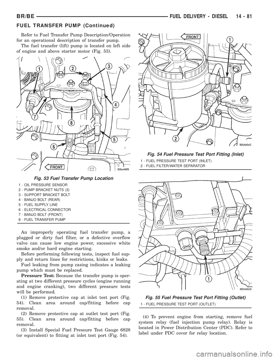
The fuel transfer (lift) pump is located on left side
of engine and above starter motor (Fig. 53).
An improperly operating fuel transfer pump, a
plugged or dirty fuel filter, or a defective overflow
valve can cause low engine power, excessive white
smoke and/or hard engine starting.
Before performing following tests, inspect fuel sup-
ply and return lines for restrictions, kinks or leaks.
Fuel leaking from pump casing indicates a leaking
pump which must be replaced.
Pressure Test:Because the transfer pump is oper-
ating at two different pressure cycles (engine running
and engine cranking), two different pressure tests
will be performed.
(1) Remove protective cap at inlet test port (Fig.
54). Clean area around cap/fitting before cap
removal.
(2) Remove protective cap at outlet test port (Fig.
55). Clean area around cap/fitting before cap
removal.
(3) Install Special Fuel Pressure Test Gauge 6828
(or equivalent) to fitting at inlet test port (Fig. 54).(4) To prevent engine from starting, remove fuel
system relay (fuel injection pump relay). Relay is
located in Power Distribution Center (PDC). Refer to
label under PDC cover for relay location.
Fig. 53 Fuel Transfer Pump Location
1 - OIL PRESSURE SENSOR
2 - PUMP BRACKET NUTS (3)
3 - SUPPORT BRACKET BOLT
4 - BANJO BOLT (REAR)
5 - FUEL SUPPLY LINE
6 - ELECTRICAL CONNECTOR
7 - BANJO BOLT (FRONT)
8 - FUEL TRANSFER PUMP
Fig. 54 Fuel Pressure Test Port Fitting (Inlet)
1 - FUEL PRESSURE TEST PORT (INLET)
2 - FUEL FILTER/WATER SEPARATOR
Fig. 55 Fuel Pressure Test Port Fitting (Outlet)
1 - FUEL PRESSURE TEST PORT (OUTLET)
BR/BEFUEL DELIVERY - DIESEL 14 - 81
FUEL TRANSFER PUMP (Continued)
Page 1569 of 2889
(5) Using key, crank engine over while observing
gauge. Pressure should be 5±7 psi.
(6) Re-install fuel system relay to PDC.
(7) Start engine and record fuel pressure. Pressure
should be aminimumof 69 kPa (10 psi) at idle
speed.
(8) Because fuel pump relay was removed, a Diag-
nostic Trouble Code (DTC) may have been set. After
testing is completed, and relay has been installed,
use DRB scan tool to remove DTC.
Pressure Drop Test:
(9) Shut engine off and remove test gauge from
inlet port test fitting. Re-attach 6828 test gauge to
outlet port (Fig. 55). Start engine and record fuel
pressure. Pressure should not be more than 34 kPa
(5 psi) lower than inlet port pressure test. If so,
replace fuel filter.
Fuel Supply Restriction Test:
Due to very small vacuum specifications, the DRB
scan tool along with the Periphal Expansion Port
(PEP) Module and 0±15 psi transducer must be used.
(10) Verify transfer pump pressure is OK before
performing restriction test.
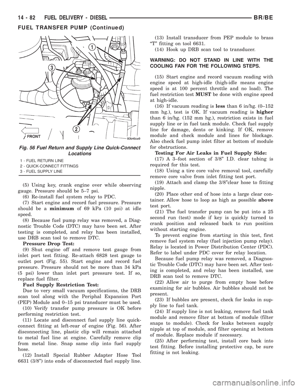
(11) Locate and disconnect fuel supply line quick-
connect fitting at left-rear of engine (Fig. 56). After
disconnecting line, plastic clip will remain attached
to metal fuel line at engine. Carefully remove clip
from metal line. Snap same clip into fuel supply
hose.
(12) Install Special Rubber Adapter Hose Tool
6631 (3/8º) into ends of disconnected fuel supply line.(13) Install transducer from PEP module to brass
ªTº fitting on tool 6631.
(14) Hook up DRB scan tool to transducer.
WARNING: DO NOT STAND IN LINE WITH THE
COOLING FAN FOR THE FOLLOWING STEPS.
(15) Start engine and record vacuum reading with
engine speed at high-idle (high-idle means engine
speed is at 100 percent throttle and no load). The
fuel restriction testMUSTbe done with engine speed
at high-idle.
(16) If vacuum reading islessthan 6 in/hg. (0±152
mm hg.), test is OK. If vacuum reading ishigher
than 6 in/hg. (152 mm hg.), restriction exists in fuel
supply line or in fuel tank module. Check fuel supply
line for damage, dents or kinking. If OK, remove
module and check module and lines for blockage.
Also check fuel pump inlet filter at bottom of module
for obstructions.
Testing For Air Leaks in Fuel Supply Side:
(17) A 3±foot section of 3/8º I.D. clear tubing is
required for this test.
(18) Using a tire core valve removal tool, carefully
remove core valve from inlet fitting test port.
(19) Attach and clamp the 3/8ºclear hose to fitting
nipple.
(20) Place other end of hose into a large clear con-
tainer. Allow hose to loop as high as possibleabove
test port.
(21) The fuel transfer pump can be put into a 25
second run (test) mode if key is quickly turned to
crank position and released back to run position
without starting engine.
To prevent engine from starting in this test, first
remove fuel system relay (fuel injection pump relay).
Relay is located in Power Distribution Center (PDC).
Refer to label under PDC cover for relay location.
Because fuel pump relay was removed, a Diagnos-
tic Trouble Code (DTC) may have been set. After test-
ing is completed, and relay has been installed, use
DRB scan tool to remove DTC.
(22) Allow air to purge from empty hose before
examining for air bubbles. Air bubbles should not be
present.
(23) If bubbles are present, check for leaks in sup-
ply line to fuel tank.
(24) If supply line is not leaking, remove fuel tank
module and remove filter at bottom of module (filter
snaps to module). Check for leaks between supply
nipple at top of module, and filter opening at bottom
of module. Replace module if necessary.
(25) After performing test, install core back into
test fitting. Before installing protective cap, be sure
fitting is not leaking.
Fig. 56 Fuel Return and Supply Line Quick-Connect
Locations
1 - FUEL RETURN LINE
2 - QUICK-CONNECT FITTINGS
3 - FUEL SUPPLY LINE
14 - 82 FUEL DELIVERY - DIESELBR/BE
FUEL TRANSFER PUMP (Continued)
Page 1572 of 2889
(1) Clean area around overflow valve and fuel
return line at injection pump before removal.
(2) Remove valve from pump and banjo fitting.
(3) Discard old sealing gaskets.
INSTALLATION
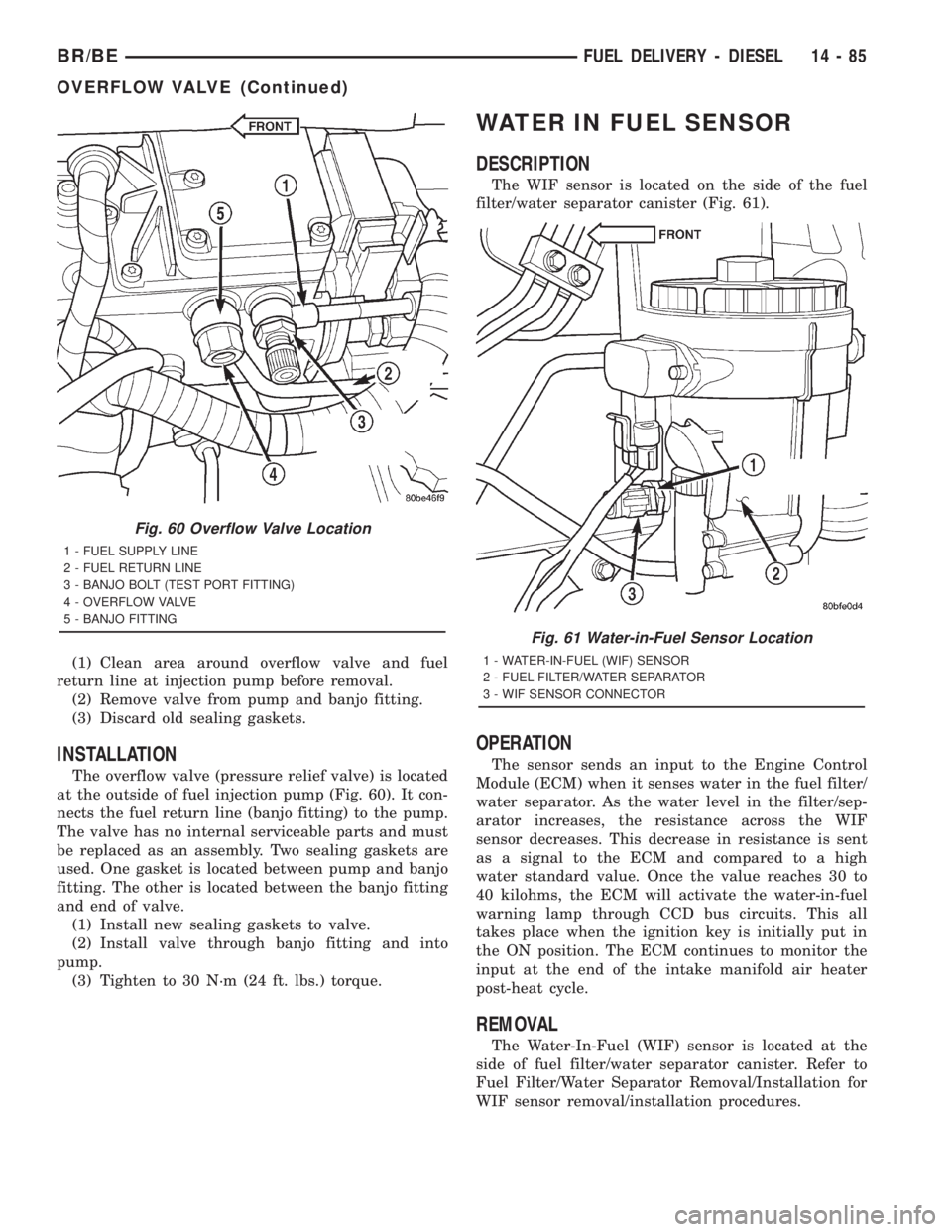
The overflow valve (pressure relief valve) is located
at the outside of fuel injection pump (Fig. 60). It con-
nects the fuel return line (banjo fitting) to the pump.
The valve has no internal serviceable parts and must
be replaced as an assembly. Two sealing gaskets are
used. One gasket is located between pump and banjo
fitting. The other is located between the banjo fitting
and end of valve.
(1) Install new sealing gaskets to valve.
(2) Install valve through banjo fitting and into
pump.
(3) Tighten to 30 N´m (24 ft. lbs.) torque.
WATER IN FUEL SENSOR
DESCRIPTION
The WIF sensor is located on the side of the fuel
filter/water separator canister (Fig. 61).
OPERATION
The sensor sends an input to the Engine Control
Module (ECM) when it senses water in the fuel filter/
water separator. As the water level in the filter/sep-
arator increases, the resistance across the WIF
sensor decreases. This decrease in resistance is sent
as a signal to the ECM and compared to a high
water standard value. Once the value reaches 30 to
40 kilohms, the ECM will activate the water-in-fuel
warning lamp through CCD bus circuits. This all
takes place when the ignition key is initially put in
the ON position. The ECM continues to monitor the
input at the end of the intake manifold air heater
post-heat cycle.
REMOVAL
The Water-In-Fuel (WIF) sensor is located at the
side of fuel filter/water separator canister. Refer to
Fuel Filter/Water Separator Removal/Installation for
WIF sensor removal/installation procedures.
Fig. 60 Overflow Valve Location
1 - FUEL SUPPLY LINE
2 - FUEL RETURN LINE
3 - BANJO BOLT (TEST PORT FITTING)
4 - OVERFLOW VALVE
5 - BANJO FITTING
Fig. 61 Water-in-Fuel Sensor Location
1 - WATER-IN-FUEL (WIF) SENSOR
2 - FUEL FILTER/WATER SEPARATOR
3 - WIF SENSOR CONNECTOR
BR/BEFUEL DELIVERY - DIESEL 14 - 85
OVERFLOW VALVE (Continued)
Page 1575 of 2889
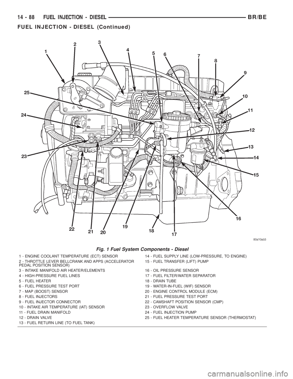
Fig. 1 Fuel System Components - Diesel
1 - ENGINE COOLANT TEMPERATURE (ECT) SENSOR 14 - FUEL SUPPLY LINE (LOW-PRESSURE, TO ENGINE)
2 - THROTTLE LEVER BELLCRANK AND APPS (ACCELERATOR
PEDAL POSITION SENSOR)15 - FUEL TRANSFER (LIFT) PUMP
3 - INTAKE MANIFOLD AIR HEATER/ELEMENTS 16 - OIL PRESSURE SENSOR
4 - HIGH-PRESSURE FUEL LINES 17 - FUEL FILTER/WATER SEPARATOR
5 - FUEL HEATER 18 - DRAIN TUBE
6 - FUEL PRESSURE TEST PORT 19 - WATER-IN-FUEL (WIF) SENSOR
7 - MAP (BOOST) SENSOR 20 - ENGINE CONTROL MODULE (ECM)
8 - FUEL INJECTORS 21 - FUEL PRESSURE TEST PORT
9 - FUEL INJECTOR CONNECTOR 22 - CAMSHAFT POSITION SENSOR (CMP)
10 - INTAKE AIR TEMPERATURE (IAT) SENSOR 23 - OVERFLOW VALVE
11 - FUEL DRAIN MANIFOLD 24 - FUEL INJECTION PUMP
12 - DRAIN VALVE 25 - FUEL HEATER TEMPERATURE SENSOR (THERMOSTAT)
13 - FUEL RETURN LINE (TO FUEL TANK)
14 - 88 FUEL INJECTION - DIESELBR/BE
FUEL INJECTION - DIESEL (Continued)
Page 1577 of 2889
SPECIFICATIONS
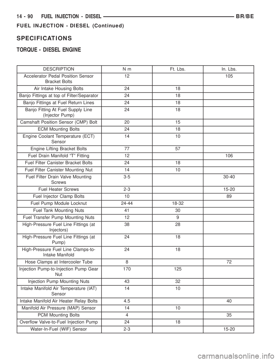
TORQUE - DIESEL ENGINE
DESCRIPTION N m Ft. Lbs. In. Lbs.
Accelerator Pedal Position Sensor
Bracket Bolts12 105
Air Intake Housing Bolts 24 18
Banjo Fittings at top of Filter/Separator 24 18
Banjo Fittings at Fuel Return Lines 24 18
Banjo Fitting At Fuel Supply Line
(Injector Pump)24 18
Camshaft Position Sensor (CMP) Bolt 20 15
ECM Mounting Bolts 24 18
Engine Coolant Temperature (ECT)
Sensor14 10
Engine Lifting Bracket Bolts 77 57
Fuel Drain Manifold ªTº Fitting 12 106
Fuel Filter Canister Bracket Bolts 24 18
Fuel Filter Canister Mounting Nut 14 10
Fuel Filter Drain Valve Mounting
Screws3-5 30-40
Fuel Heater Screws 2-3 15-20
Fuel Injector Clamp Bolts 10 89
Fuel Pump Module Locknut 24-44 18-32
Fuel Tank Mounting Nuts 41 30
Fuel Transfer Pump Mounting Nuts 12 9
High-Pressure Fuel Line Fittings (at
Injectors)38 28
High-Pressure Fuel Line Fittings (at
Pump)24 18
High-Pressure Fuel Line Clamps-to-
Intake Manifold24 18
Hose Clamps at Intercooler Tube 8 72
Injection Pump-to-Injection Pump Gear
Nut170 125
Injection Pump Mounting Nuts 43 32
Intake Manifold Air Temperature (IAT)
Sensor14 10
Intake Manifold Air Heater Relay Bolts 4.5 40
Manifold Air Pressure (MAP) Sensor 14 10
PCM Mounting Bolts 4 35
Overflow Valve-to-Fuel Injection Pump 24 18
Water-In-Fuel (WIF) Sensor 2-3 15-20
14 - 90 FUEL INJECTION - DIESELBR/BE
FUEL INJECTION - DIESEL (Continued)
Page 1581 of 2889
OPERATION
High-pressure fuel is supplied from the injection
pump, through a high-pressure fuel line, through a
steel connector and into the fuel injector. When fuel
pressure rises to approximately 31,026 kPa (4,500
psi), the needle valve spring tension is overcome. The
needle valve rises and fuel flows through the spray
holes in the nozzle tip into the combustion chamber.
The pressure required to lift the needle valve is the
nozzle opening pressure. This is sometimes referred
to as the ªpopº pressure setting.
Each fuel injector is connected to each high-pres-
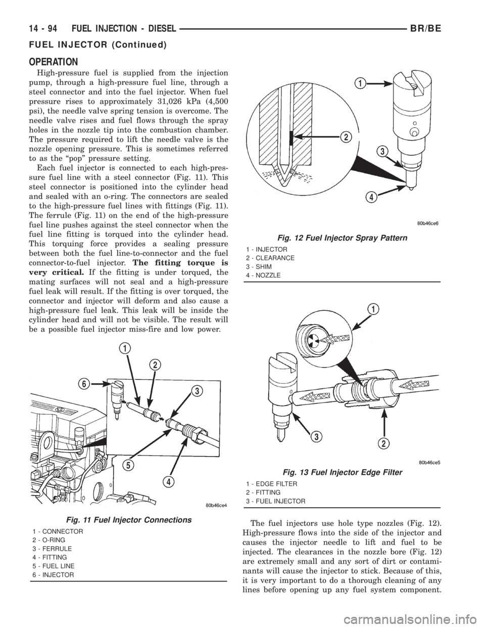
sure fuel line with a steel connector (Fig. 11). This
steel connector is positioned into the cylinder head
and sealed with an o-ring. The connectors are sealed
to the high-pressure fuel lines with fittings (Fig. 11).
The ferrule (Fig. 11) on the end of the high-pressure
fuel line pushes against the steel connector when the
fuel line fitting is torqued into the cylinder head.
This torquing force provides a sealing pressure
between both the fuel line-to-connector and the fuel
connector-to-fuel injector.The fitting torque is
very critical.If the fitting is under torqued, the
mating surfaces will not seal and a high-pressure
fuel leak will result. If the fitting is over torqued, the
connector and injector will deform and also cause a
high-pressure fuel leak. This leak will be inside the
cylinder head and will not be visible. The result will
be a possible fuel injector miss-fire and low power.
The fuel injectors use hole type nozzles (Fig. 12).
High-pressure flows into the side of the injector and
causes the injector needle to lift and fuel to be
injected. The clearances in the nozzle bore (Fig. 12)
are extremely small and any sort of dirt or contami-
nants will cause the injector to stick. Because of this,
it is very important to do a thorough cleaning of any
lines before opening up any fuel system component.
Fig. 11 Fuel Injector Connections
1 - CONNECTOR
2 - O-RING
3 - FERRULE
4 - FITTING
5 - FUEL LINE
6 - INJECTOR
Fig. 12 Fuel Injector Spray Pattern
1 - INJECTOR
2 - CLEARANCE
3 - SHIM
4 - NOZZLE
Fig. 13 Fuel Injector Edge Filter
1 - EDGE FILTER
2 - FITTING
3 - FUEL INJECTOR
14 - 94 FUEL INJECTION - DIESELBR/BE
FUEL INJECTOR (Continued)
Page 1582 of 2889
Always cover or cap any open fuel connections before
a fuel system repair is performed.
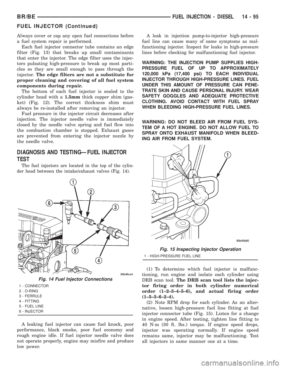
Each fuel injector connector tube contains an edge
filter (Fig. 13) that breaks up small contaminants
that enter the injector. The edge filter uses the injec-
tors pulsating high-pressure to break up most parti-
cles so they are small enough to pass through the
injector.The edge filters are not a substitute for
proper cleaning and covering of all fuel system
components during repair.
The bottom of each fuel injector is sealed to the
cylinder head with a1.5mmthick copper shim (gas-
ket) (Fig. 12). The correct thickness shim must
always be re-installed after removing an injector.
Fuel pressure in the injector circuit decreases after
injection. The injector needle valve is immediately
closed by the needle valve spring and fuel flow into
the combustion chamber is stopped. Exhaust gases
are prevented from entering the injector nozzle by
the needle valve.
DIAGNOSIS AND TESTINGÐFUEL INJECTOR
TEST
The fuel injectors are located in the top of the cylin-
der head between the intake/exhaust valves (Fig. 14).
A leaking fuel injector can cause fuel knock, poor
performance, black smoke, poor fuel economy and
rough engine idle. If fuel injector needle valve does
not operate properly, engine may misfire and produce
low power.
A leak in injection pump-to-injector high-pressure
fuel line can cause many of same symptoms as mal-
functioning injector. Inspect for leaks in high-pressure
lines before checking for malfunctioning fuel injector.
WARNING: THE INJECTION PUMP SUPPLIES HIGH-
PRESSURE FUEL OF UP TO APPROXIMATELY
120,000 kPa (17,400 psi) TO EACH INDIVIDUAL
INJECTOR THROUGH HIGH-PRESSURE LINES. FUEL
UNDER THIS AMOUNT OF PRESSURE CAN PENE-
TRATE SKIN AND CAUSE PERSONAL INJURY. WEAR
SAFETY GOGGLES AND ADEQUATE PROTECTIVE
CLOTHING. AVOID CONTACT WITH FUEL SPRAY
WHEN BLEEDING HIGH-PRESSURE FUEL LINES.
WARNING: DO NOT BLEED AIR FROM FUEL SYS-
TEM OF A HOT ENGINE. DO NOT ALLOW FUEL TO
SPRAY ONTO EXHAUST MANIFOLD WHEN BLEED-
ING AIR FROM FUEL SYSTEM.
(1) To determine which fuel injector is malfunc-
tioning, run engine and isolate each cylinder using
DRB scan tool.The DRB scan tool lists the injec-
tor firing order in both cylinder numerical
order (1±2±3±4±5±6), and actual firing order
(1±5±3±6±2±4).
(2) Note RPM drop for each cylinder. As an alter-
native, loosen high-pressure fuel line fitting at fuel
injector connector tube (Fig. 15). Listen for a change
in engine speed. After testing, tighten line fitting to
40 N´m (30 ft. lbs.) torque. If engine speed drops,
injector was operating normally. If engine speed
remains same, injector may be malfunctioning. Test
all injectors in same manner one at a time.
Fig. 14 Fuel Injector Connections
1 - CONNECTOR
2 - O-RING
3 - FERRULE
4 - FITTING
5 - FUEL LINE
6 - INJECTOR
Fig. 15 Inspecting Injector Operation
1 - HIGH-PRESSURE FUEL LINE
BR/BEFUEL INJECTION - DIESEL 14 - 95
FUEL INJECTOR (Continued)