2001 DODGE RAM fuel filter
[x] Cancel search: fuel filterPage 1525 of 2889
CRANKSHAFT POSITION
SENSOR
DESCRIPTION - 3.9L
The Crankshaft Position (CKP) sensor is located
near the outer edge of the flywheel (starter ringear).
DESCRIPTION - 5.2L/5.9L
The Crankshaft Position (CKP) sensor is located
near the outer edge of the flywheel (starter ringear).
DESCRIPTION - 8.0L
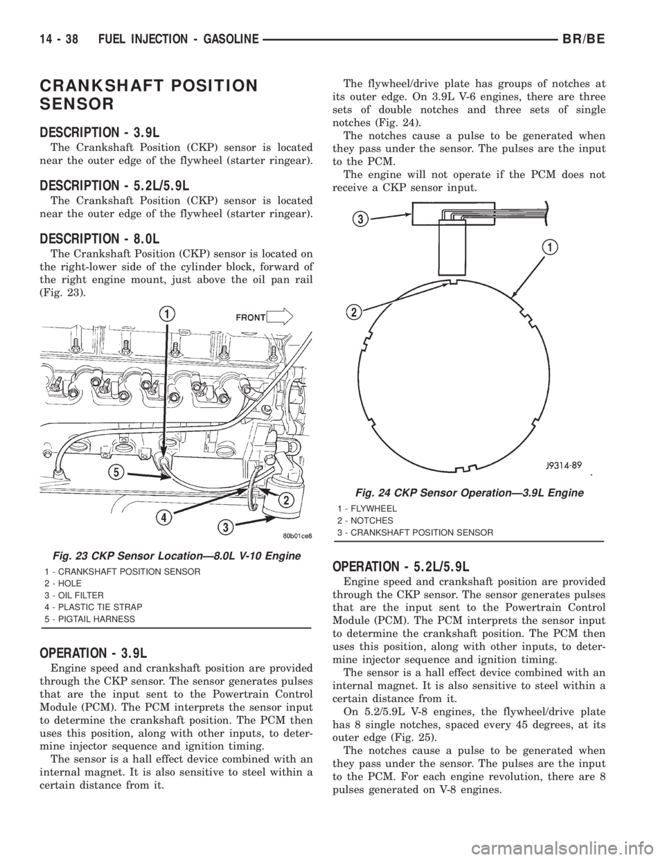
The Crankshaft Position (CKP) sensor is located on
the right-lower side of the cylinder block, forward of
the right engine mount, just above the oil pan rail
(Fig. 23).
OPERATION - 3.9L
Engine speed and crankshaft position are provided
through the CKP sensor. The sensor generates pulses
that are the input sent to the Powertrain Control
Module (PCM). The PCM interprets the sensor input
to determine the crankshaft position. The PCM then
uses this position, along with other inputs, to deter-
mine injector sequence and ignition timing.
The sensor is a hall effect device combined with an
internal magnet. It is also sensitive to steel within a
certain distance from it.The flywheel/drive plate has groups of notches at
its outer edge. On 3.9L V-6 engines, there are three
sets of double notches and three sets of single
notches (Fig. 24).
The notches cause a pulse to be generated when
they pass under the sensor. The pulses are the input
to the PCM.
The engine will not operate if the PCM does not
receive a CKP sensor input.
OPERATION - 5.2L/5.9L
Engine speed and crankshaft position are provided
through the CKP sensor. The sensor generates pulses
that are the input sent to the Powertrain Control
Module (PCM). The PCM interprets the sensor input
to determine the crankshaft position. The PCM then
uses this position, along with other inputs, to deter-
mine injector sequence and ignition timing.
The sensor is a hall effect device combined with an
internal magnet. It is also sensitive to steel within a
certain distance from it.
On 5.2/5.9L V-8 engines, the flywheel/drive plate
has 8 single notches, spaced every 45 degrees, at its
outer edge (Fig. 25).
The notches cause a pulse to be generated when
they pass under the sensor. The pulses are the input
to the PCM. For each engine revolution, there are 8
pulses generated on V-8 engines.
Fig. 23 CKP Sensor LocationÐ8.0L V-10 Engine
1 - CRANKSHAFT POSITION SENSOR
2 - HOLE
3 - OIL FILTER
4 - PLASTIC TIE STRAP
5 - PIGTAIL HARNESS
Fig. 24 CKP Sensor OperationÐ3.9L Engine
1 - FLYWHEEL
2 - NOTCHES
3 - CRANKSHAFT POSITION SENSOR
14 - 38 FUEL INJECTION - GASOLINEBR/BE
Page 1527 of 2889

REMOVAL - 8.0L
The crankshaft position sensor is located on the
right-lower side of the cylinder block, forward of the
right engine mount, just above the oil pan rail (Fig.
28).
(1) Raise and support vehicle.
(2) Disconnect sensor pigtail harness from main
engine wiring harness.
(3) Remove sensor mounting bolt (Fig. 29).
(4) Cut plastic tie strap (Fig. 28) securing sensor
pigtail harness to side of engine block.
(5) Carefully pry sensor from cylinder block in a
rocking action with two small screwdrivers.
(6) Remove sensor from vehicle.
(7) Check condition of sensor o-ring (Fig. 30).
INSTALLATION - 3.9L/5.2L/5.9L
(1) Position crankshaft position sensor to engine.
(2) Install mounting bolts and tighten to 8 N´m (70
in. lbs.) torque.
(3) Connect main harness electrical connector to
sensor.
(4) Install air cleaner tube.
INSTALLATION - 8.0L
The crankshaft position sensor is located on the
right-lower side of the cylinder block, forward of the
right engine mount, just above the oil pan rail (Fig.
28).(1) Apply a small amount of engine oil to sensor
o-ring (Fig. 30).
(2) Install sensor into cylinder block with a slight
rocking action. Do not twist sensor into position as
damage to o-ring may result.
CAUTION: Before tightening sensor mounting bolt,
be sure sensor is completely flush to cylinder block
(Fig. 29). If sensor is not flush, damage to sensor
mounting tang may result.
(3) Install mounting bolt and tighten to 8 N´m (70
in. lbs.) torque.
(4) Connect sensor pigtail harness to main engine
wiring harness
Fig. 28 Crankshaft Position Sensor LocationÐ8.0L
V-10 Engine
1 - CRANKSHAFT POSITION SENSOR
2 - HOLE
3 - OIL FILTER
4 - PLASTIC TIE STRAP
5 - PIGTAIL HARNESS
Fig. 29 Sensor Removal/InstallationÐ8.0L V-10
Engine
1 - CRANKSHAFT POSITION SENSOR
2 - MOUNTING BOLT
3 - SENSOR POSITIONED FLUSH TO CYLINDER BLOCK
Fig. 30 Sensor O-RingÐ8.0L V-10 Engine
1 - CRANKSHAFT POSITION SENSOR O-RING
2 - ELECTRICAL CONNECTOR
3 - PIGTAIL HARNESS
14 - 40 FUEL INJECTION - GASOLINEBR/BE
CRANKSHAFT POSITION SENSOR (Continued)
Page 1535 of 2889
WARNING: THE EXHAUST MANIFOLD, EXHAUST
PIPES AND CATALYTIC CONVERTER BECOME
VERY HOT DURING ENGINE OPERATION. ALLOW
ENGINE TO COOL BEFORE REMOVING OXYGEN
SENSOR.
(1) Raise and support the vehicle.
(2) Disconnect the wire connector from the O2S
sensor.
CAUTION: When disconnecting the sensor electrical
connector, do not pull directly on wire going into
sensor.
(3) Remove the O2S sensor with an oxygen sensor
removal and installation tool.
INSTALLATION
Threads of new oxygen sensors are factory coated
with anti-seize compound to aid in removal.DO
NOT add any additional anti-seize compound to
the threads of a new oxygen sensor.
(1) Install the O2S sensor. Tighten to 30 N´m (22
ft. lbs.) torque.
(2) Connect the O2S sensor wire connector.
(3) Lower the vehicle.
PTO SWITCH
DESCRIPTION
This Powertrain Control Module (PCM) input is
used only on models equipped with aftermarket
Power Take Off (PTO) units.
OPERATION
The input is used only to tell the PCM that the
PTO has been engaged. The PCM will disable (tem-
porarily shut down) certain OBD II diagnostic trou-
ble codes when the PTO is engaged.
When the aftermarket PTO switch has been
engaged, a 12V + signal is sent through circuit G113
to PCM pin A13. The PCM will then sense and deter-
mine that the PTO has been activated.
THROTTLE BODY
DESCRIPTION
The throttle body is located on the intake manifold.
Fuel does not enter the intake manifold through the
throttle body. Fuel is sprayed into the manifold by
the fuel injectors.
OPERATION
Filtered air from the air cleaner enters the intake
manifold through the throttle body. The throttle body
contains an air control passage controlled by an Idle
Air Control (IAC) motor. The air control passage is
used to supply air for idle conditions. A throttle valve
(plate) is used to supply air for above idle conditions.
Certain sensors are attached to the throttle body.
The accelerator pedal cable, speed control cable and
transmission control cable (when equipped) are con-
nected to the throttle body linkage arm.
A (factory adjusted) set screw is used to mechani-
cally limit the position of the throttle body throttle
plate.Never attempt to adjust the engine idle
speed using this screw.All idle speed functions are
controlled by the PCM.
REMOVAL - 3.9L/5.2L/5.9L
A (factory adjusted) set screw is used to mechani-
cally limit the position of the throttle body throttle
plate.Never attempt to adjust the engine idle
speed using this screw.All idle speed functions are
controlled by the powertrain control module (PCM).
(1) Remove the air cleaner.
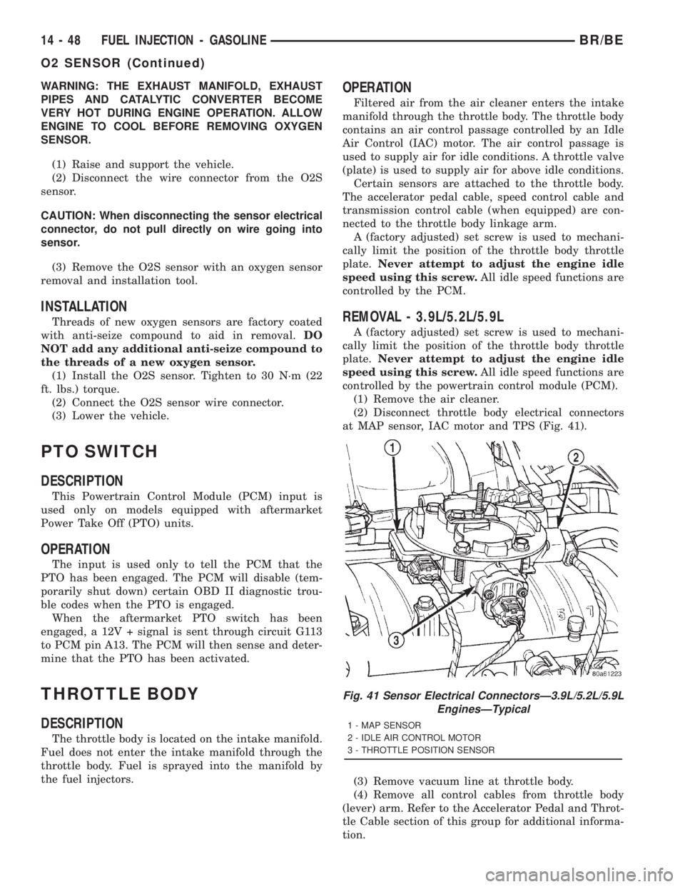
(2) Disconnect throttle body electrical connectors
at MAP sensor, IAC motor and TPS (Fig. 41).
(3) Remove vacuum line at throttle body.
(4) Remove all control cables from throttle body
(lever) arm. Refer to the Accelerator Pedal and Throt-
tle Cable section of this group for additional informa-
tion.
Fig. 41 Sensor Electrical ConnectorsÐ3.9L/5.2L/5.9L
EnginesÐTypical
1 - MAP SENSOR
2 - IDLE AIR CONTROL MOTOR
3 - THROTTLE POSITION SENSOR
14 - 48 FUEL INJECTION - GASOLINEBR/BE
O2 SENSOR (Continued)
Page 1541 of 2889
FUEL DELIVERY - DIESEL
TABLE OF CONTENTS
page page
FUEL DELIVERY - DIESEL
DESCRIPTION...........................54
OPERATION.............................56
DIAGNOSIS AND TESTING.................56
AIR IN FUEL SYSTEM...................56
FUEL SUPPLY RESTRICTIONS............56
STANDARD PROCEDURE..................56
WATER DRAINING AT FUEL FILTER........56
CLEANING FUEL SYSTEM PARTS..........57
AIR BLEED............................57
SPECIFICATIONS........................58
SPECIAL TOOLS.........................59
FUEL FILTER / WATER SEPARATOR
DESCRIPTION...........................59
OPERATION.............................59
REMOVAL..............................60
INSTALLATION...........................61
FUEL HEATER
DESCRIPTION...........................62
OPERATION.............................62
DIAGNOSIS AND TESTING.................62
FUEL HEATER.........................62
REMOVAL..............................63
FUEL HEATER RELAY
DESCRIPTION...........................63
OPERATION.............................63
DIAGNOSIS AND TESTING.................64
FUEL HEATER RELAY...................64
REMOVAL..............................65
INSTALLATION...........................65
FUEL INJECTION PUMP
DESCRIPTION...........................65
OPERATION.............................66
DIAGNOSIS AND TESTING.................66
FUEL INJECTION PUMP TIMING...........66
REMOVAL..............................68
INSTALLATION...........................71
FUEL INJECTION PUMP DATA PLATE
SPECIFICATIONS........................73FUEL LEVEL SENDING UNIT / SENSOR
DESCRIPTION...........................73
OPERATION.............................73
FUEL LINES
DESCRIPTION...........................73
OPERATION.............................74
DIAGNOSIS AND TESTING.................74
HIGH-PRESSURE FUEL LINE LEAK.........74
REMOVAL..............................75
INSTALLATION...........................77
FUEL TANK
DESCRIPTION...........................78
FUEL TANK MODULE
DESCRIPTION...........................78
OPERATION.............................78
REMOVAL..............................78
INSTALLATION...........................79
FUEL TRANSFER PUMP
DESCRIPTION...........................79
OPERATION.............................79
DIAGNOSIS AND TESTING.................80
FUEL TRANSFER PUMP PRESSURE........80
REMOVAL..............................83
INSTALLATION...........................83
OVERFLOW VALVE
DESCRIPTION...........................83
OPERATION.............................83
DIAGNOSIS AND TESTING.................84
OVERFLOW VALVE.....................84
REMOVAL..............................84
INSTALLATION...........................85
WATER IN FUEL SENSOR
DESCRIPTION...........................85
OPERATION.............................85
REMOVAL..............................85
FUEL DRAIN MANIFOLD
DESCRIPTION...........................86
OPERATION.............................86
REMOVAL..............................86
INSTALLATION...........................86
FUEL DELIVERY - DIESEL
DESCRIPTION - DIESEL FUEL DELIVERY
SYSTEM
The fuel system on the Cummins 24 valveÐTurbo
Diesel Engine uses anelectronicfuel injection
pump with three control modules.Also refer to the Powertrain Control Module (PCM)
or Engine Control Module sections.
Some fuel system components are shown in (Fig.
1).
The fuel delivery system consists of the:
²Accelerator pedal
²Air cleaner housing/element
²Fuel drain manifold (passage)
14 - 54 FUEL DELIVERY - DIESELBR/BE
Page 1542 of 2889
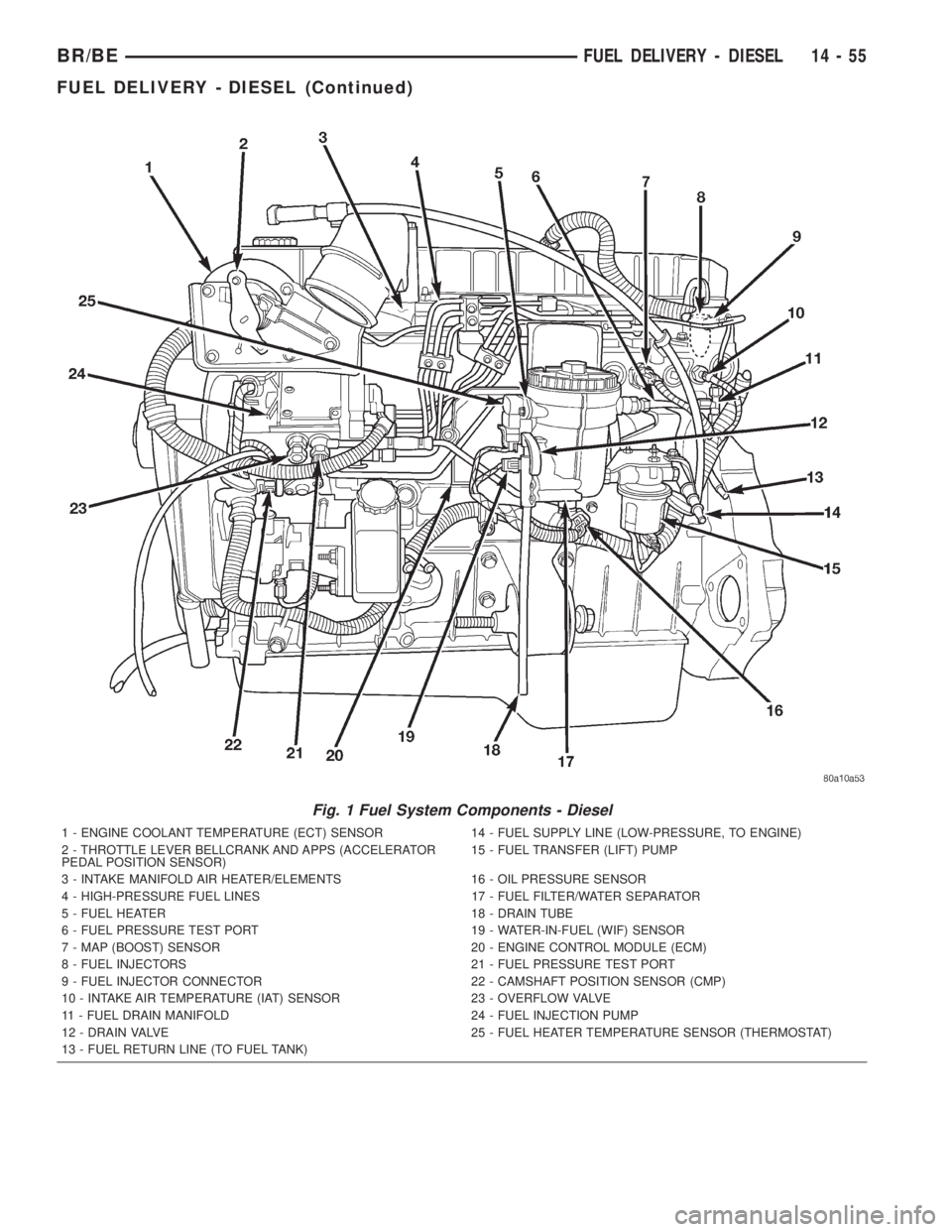
Fig. 1 Fuel System Components - Diesel
1 - ENGINE COOLANT TEMPERATURE (ECT) SENSOR 14 - FUEL SUPPLY LINE (LOW-PRESSURE, TO ENGINE)
2 - THROTTLE LEVER BELLCRANK AND APPS (ACCELERATOR
PEDAL POSITION SENSOR)15 - FUEL TRANSFER (LIFT) PUMP
3 - INTAKE MANIFOLD AIR HEATER/ELEMENTS 16 - OIL PRESSURE SENSOR
4 - HIGH-PRESSURE FUEL LINES 17 - FUEL FILTER/WATER SEPARATOR
5 - FUEL HEATER 18 - DRAIN TUBE
6 - FUEL PRESSURE TEST PORT 19 - WATER-IN-FUEL (WIF) SENSOR
7 - MAP (BOOST) SENSOR 20 - ENGINE CONTROL MODULE (ECM)
8 - FUEL INJECTORS 21 - FUEL PRESSURE TEST PORT
9 - FUEL INJECTOR CONNECTOR 22 - CAMSHAFT POSITION SENSOR (CMP)
10 - INTAKE AIR TEMPERATURE (IAT) SENSOR 23 - OVERFLOW VALVE
11 - FUEL DRAIN MANIFOLD 24 - FUEL INJECTION PUMP
12 - DRAIN VALVE 25 - FUEL HEATER TEMPERATURE SENSOR (THERMOSTAT)
13 - FUEL RETURN LINE (TO FUEL TANK)
BR/BEFUEL DELIVERY - DIESEL 14 - 55
FUEL DELIVERY - DIESEL (Continued)
Page 1543 of 2889
²Fuel filter/water separator
²Fuel heater
²Fuel heater relay
²Fuel transfer (lift) pump
²Fuel injection pump
²Fuel injectors
²Fuel heater temperature sensor
²Fuel tank
²Fuel tank filler/vent tube assembly
²Fuel tank filler tube cap
²Fuel tank module containing the rollover valve,
fuel gauge sending unit (fuel level sensor) and a sep-
arate fuel filter located at bottom of tank module
²Fuel tubes/lines/hoses
²High-pressure fuel injector lines
²In-tank fuel filter (at bottom of fuel tank mod-
ule)
²Low-pressure fuel supply lines
²Low-pressure fuel return line
²Overflow valve
²Quick-connect fittings
²Throttle cable
²Water draining
OPERATION
WARNING: HIGH-PRESSURE FUEL LINES DELIVER
DIESEL FUEL UNDER EXTREME PRESSURE FROM
THE INJECTION PUMP TO THE FUEL INJECTORS.
THIS MAY BE AS HIGH AS 120,000 KPA (17,405
PSI). USE EXTREME CAUTION WHEN INSPECTING
FOR HIGH-PRESSURE FUEL LEAKS. INSPECT FOR
HIGH-PRESSURE FUEL LEAKS WITH A SHEET OF
CARDBOARD. HIGH FUEL INJECTION PRESSURE
CAN CAUSE PERSONAL INJURY IF CONTACT IS
MADE WITH THE SKIN.
DIAGNOSIS AND TESTING - AIR IN FUEL
SYSTEM
Air will enter the fuel system whenever fuel supply
lines, separator filters, injection pump, high-pressure
lines or injectors are removed or disconnected. Air
trapped in the fuel system can result in hard start-
ing, a rough running engine, engine misfire, low
power, excessive smoke and fuel knock. After service
is performed, air must be bled from the system
before starting the engine.Inspect the fuel system from the fuel transfer
pump to the injectors for loose connections. Leaking
fuel is an indicator of loose connections or defective
seals. Air can also enter the fuel system between the
fuel tank and the transfer pump. Inspect the fuel
tank and fuel lines for damage that might allow air
into the system.
For air bleeding, refer to the Air Bleed Procedure.
DIAGNOSIS AND TESTING - FUEL SUPPLY
RESTRICTIONS
LOW-PRESSURE LINES
Fuel supply line restrictions or a defective fuel
transfer pump can cause starting problems and pre-
vent engine from accelerating. The starting problems
include; low power and/or white fog like exhaust.
Test all fuel supply lines for restrictions or block-
age. Flush or replace as necessary. Bleed fuel system
of air once a fuel supply line has been replaced. Refer
to Air Bleed Procedure for procedures.
To test for fuel line restrictions, a vacuum restric-
tion test may be performed. Refer to Fuel Transfer
Pump Pressure Test.
HIGH-PRESSURE LINES
Restricted (kinked or bent) high-pressure lines can
cause starting problems, poor engine performance,
engine mis-fire and white smoke from exhaust.
Examine all high-pressure lines for any damage.
Each radius on each high-pressure line must be
smooth and free of any bends or kinks.
Replace damaged, restricted or leaking high-pres-
sure fuel lines with correct replacement line.
CAUTION: All high-pressure fuel lines must be
clamped securely in place in holders. Lines cannot
contact each other or other components. Do not
attempt to weld high-pressure fuel lines or to repair
lines that are damaged. If line is kinked or bent, it
must be replaced. Use only recommended lines
when replacement of high-pressure fuel line is nec-
essary.
STANDARD PROCEDURES - WATER DRAINING
AT FUEL FILTER
Refer to Fuel Filter/Water Separator removal/in-
stallation for procedures.
14 - 56 FUEL DELIVERY - DIESELBR/BE
FUEL DELIVERY - DIESEL (Continued)
Page 1545 of 2889
WARNING: THE FUEL INJECTION PUMP SUPPLIES
EXTREMELY HIGH FUEL PRESSURE TO EACH INDI-
VIDUAL INJECTOR THROUGH THE HIGH-PRES-
SURE LINES. FUEL UNDER THIS AMOUNT OF
PRESSURE CAN PENETRATE THE SKIN AND
CAUSE PERSONAL INJURY. WEAR SAFETY GOG-
GLES AND ADEQUATE PROTECTIVE CLOTHING
AND AVOID CONTACT WITH FUEL SPRAY WHEN
BLEEDING HIGH-PRESSURE FUEL LINES.
WARNING: ENGINE MAY START WHILE CRANKING
STARTER MOTOR.
Engine may start, may run erratically and be
very noisy for a few minutes. This is a normal
condition.
(9) Thoroughly clean area around injector fittings
where they join injector connector tubes.
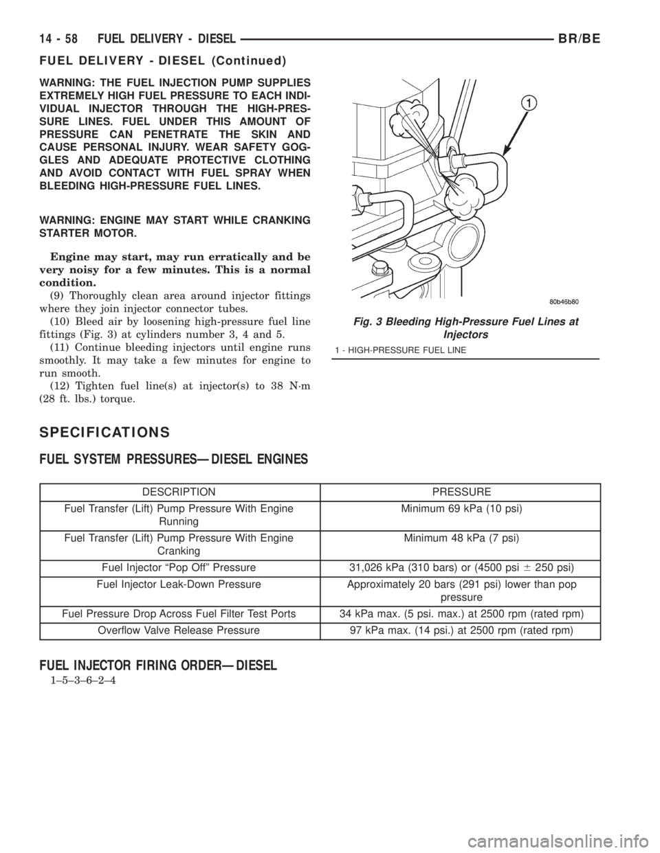
(10) Bleed air by loosening high-pressure fuel line
fittings (Fig. 3) at cylinders number 3, 4 and 5.
(11) Continue bleeding injectors until engine runs
smoothly. It may take a few minutes for engine to
run smooth.
(12) Tighten fuel line(s) at injector(s) to 38 N´m
(28 ft. lbs.) torque.
SPECIFICATIONS
FUEL SYSTEM PRESSURESÐDIESEL ENGINES
DESCRIPTION PRESSURE
Fuel Transfer (Lift) Pump Pressure With Engine
RunningMinimum 69 kPa (10 psi)
Fuel Transfer (Lift) Pump Pressure With Engine
CrankingMinimum 48 kPa (7 psi)
Fuel Injector ªPop Offº Pressure 31,026 kPa (310 bars) or (4500 psi6250 psi)
Fuel Injector Leak-Down Pressure Approximately 20 bars (291 psi) lower than pop
pressure
Fuel Pressure Drop Across Fuel Filter Test Ports 34 kPa max. (5 psi. max.) at 2500 rpm (rated rpm)
Overflow Valve Release Pressure 97 kPa max. (14 psi.) at 2500 rpm (rated rpm)
FUEL INJECTOR FIRING ORDERÐDIESEL
1±5±3±6±2±4
Fig. 3 Bleeding High-Pressure Fuel Lines at
Injectors
1 - HIGH-PRESSURE FUEL LINE
14 - 58 FUEL DELIVERY - DIESELBR/BE
FUEL DELIVERY - DIESEL (Continued)
Page 1546 of 2889
SPECIAL TOOLS
DIESEL FUEL SYSTEMFUEL FILTER / WATER
SEPARATOR
DESCRIPTION
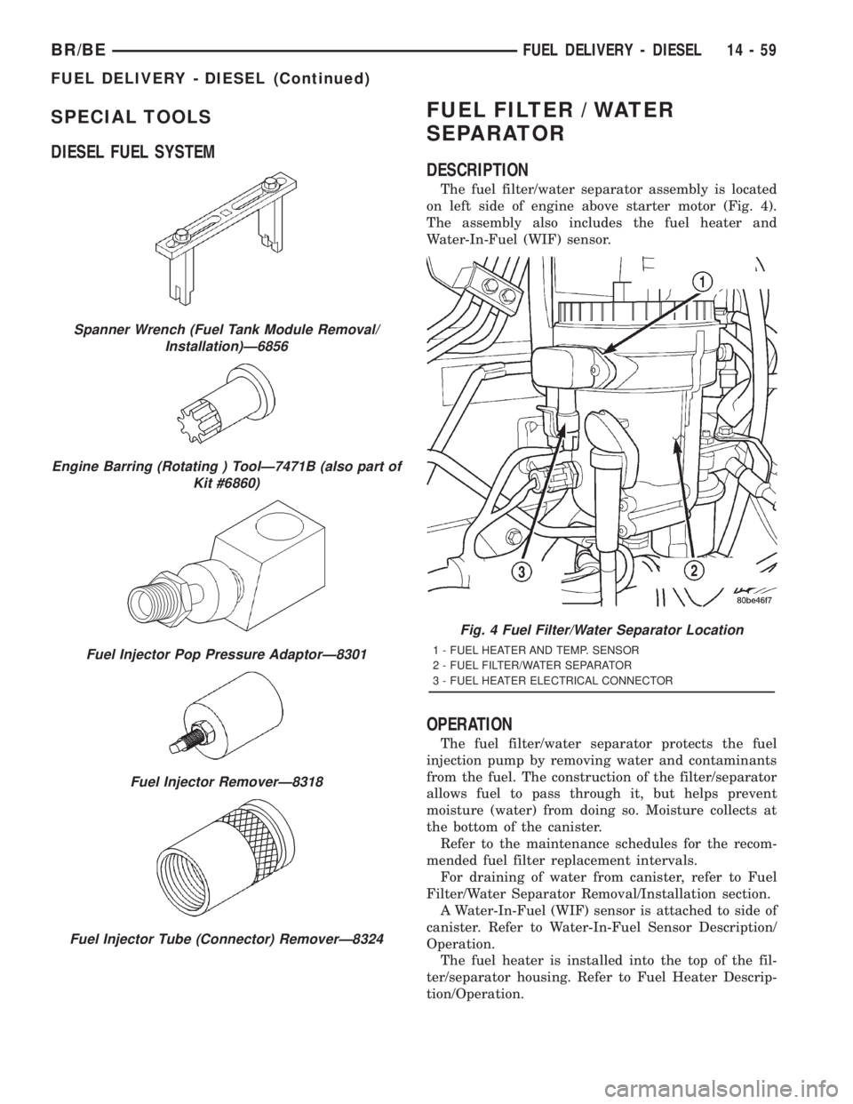
The fuel filter/water separator assembly is located
on left side of engine above starter motor (Fig. 4).
The assembly also includes the fuel heater and
Water-In-Fuel (WIF) sensor.
OPERATION
The fuel filter/water separator protects the fuel
injection pump by removing water and contaminants
from the fuel. The construction of the filter/separator
allows fuel to pass through it, but helps prevent
moisture (water) from doing so. Moisture collects at
the bottom of the canister.
Refer to the maintenance schedules for the recom-
mended fuel filter replacement intervals.
For draining of water from canister, refer to Fuel
Filter/Water Separator Removal/Installation section.
A Water-In-Fuel (WIF) sensor is attached to side of
canister. Refer to Water-In-Fuel Sensor Description/
Operation.
The fuel heater is installed into the top of the fil-
ter/separator housing. Refer to Fuel Heater Descrip-
tion/Operation.
Spanner Wrench (Fuel Tank Module Removal/
Installation)Ð6856
Engine Barring (Rotating ) ToolÐ7471B (also part of
Kit #6860)
Fuel Injector Pop Pressure AdaptorÐ8301
Fuel Injector RemoverÐ8318
Fuel Injector Tube (Connector) RemoverÐ8324
Fig. 4 Fuel Filter/Water Separator Location
1 - FUEL HEATER AND TEMP. SENSOR
2 - FUEL FILTER/WATER SEPARATOR
3 - FUEL HEATER ELECTRICAL CONNECTOR
BR/BEFUEL DELIVERY - DIESEL 14 - 59
FUEL DELIVERY - DIESEL (Continued)