2001 DODGE RAM fuel filter
[x] Cancel search: fuel filterPage 1547 of 2889
REMOVAL
Refer to maintenance schedules in this manual for
recommended fuel filter replacement intervals.
Draining water from fuel filter/water separa-
tor housing:
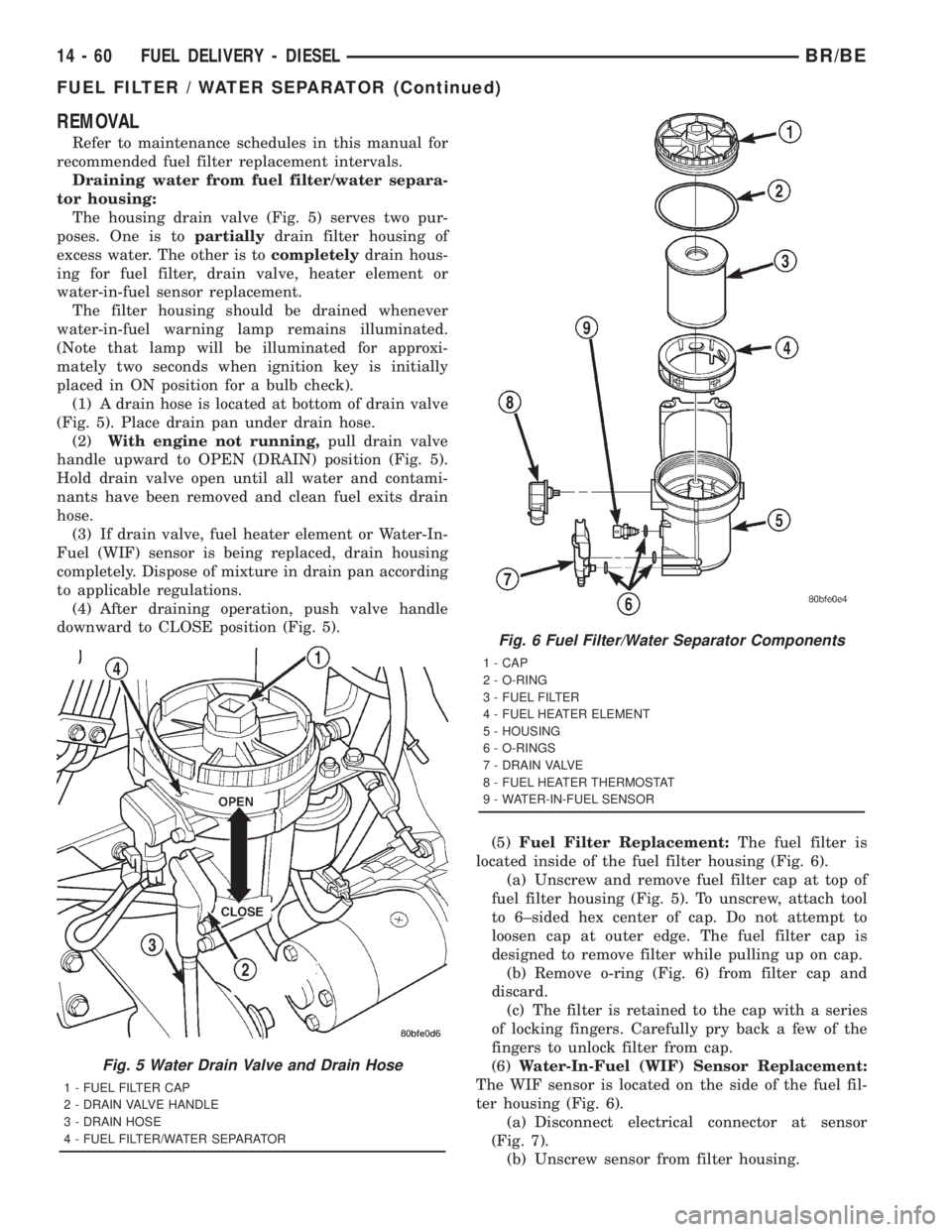
The housing drain valve (Fig. 5) serves two pur-
poses. One is topartiallydrain filter housing of
excess water. The other is tocompletelydrain hous-
ing for fuel filter, drain valve, heater element or
water-in-fuel sensor replacement.
The filter housing should be drained whenever
water-in-fuel warning lamp remains illuminated.
(Note that lamp will be illuminated for approxi-
mately two seconds when ignition key is initially
placed in ON position for a bulb check).
(1) A drain hose is located at bottom of drain valve
(Fig. 5). Place drain pan under drain hose.
(2)With engine not running,pull drain valve
handle upward to OPEN (DRAIN) position (Fig. 5).
Hold drain valve open until all water and contami-
nants have been removed and clean fuel exits drain
hose.
(3) If drain valve, fuel heater element or Water-In-
Fuel (WIF) sensor is being replaced, drain housing
completely. Dispose of mixture in drain pan according
to applicable regulations.
(4) After draining operation, push valve handle
downward to CLOSE position (Fig. 5).
(5)Fuel Filter Replacement:The fuel filter is
located inside of the fuel filter housing (Fig. 6).
(a) Unscrew and remove fuel filter cap at top of
fuel filter housing (Fig. 5). To unscrew, attach tool
to 6±sided hex center of cap. Do not attempt to
loosen cap at outer edge. The fuel filter cap is
designed to remove filter while pulling up on cap.
(b) Remove o-ring (Fig. 6) from filter cap and
discard.
(c) The filter is retained to the cap with a series
of locking fingers. Carefully pry back a few of the
fingers to unlock filter from cap.
(6)Water-In-Fuel (WIF) Sensor Replacement:
The WIF sensor is located on the side of the fuel fil-
ter housing (Fig. 6).
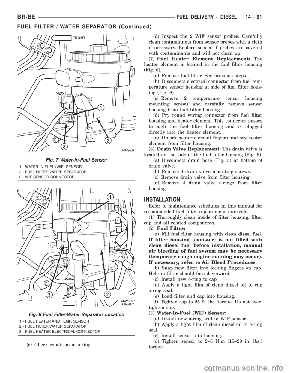
(a) Disconnect electrical connector at sensor
(Fig. 7).
(b) Unscrew sensor from filter housing.
Fig. 5 Water Drain Valve and Drain Hose
1 - FUEL FILTER CAP
2 - DRAIN VALVE HANDLE
3 - DRAIN HOSE
4 - FUEL FILTER/WATER SEPARATOR
Fig. 6 Fuel Filter/Water Separator Components
1 - CAP
2 - O-RING
3 - FUEL FILTER
4 - FUEL HEATER ELEMENT
5 - HOUSING
6 - O-RINGS
7 - DRAIN VALVE
8 - FUEL HEATER THERMOSTAT
9 - WATER-IN-FUEL SENSOR
14 - 60 FUEL DELIVERY - DIESELBR/BE
FUEL FILTER / WATER SEPARATOR (Continued)
Page 1548 of 2889
(c) Check condition of o-ring.(d) Inspect the 2 WIF sensor probes. Carefully
clean contaminants from sensor probes with a cloth
if necessary. Replace sensor if probes are covered
with contaminants and will not clean up.
(7)Fuel Heater Element Replacement:The
heater element is located in the fuel filter housing
(Fig. 6).
(a) Remove fuel filter. See previous steps.
(b) Disconnect electrical connector from fuel tem-
perature sensor housing at side of fuel filter hous-
ing (Fig. 8).
(c) Remove 2 temperature sensor housing
mounting screws and carefully remove sensor
housing from fuel filter housing.
(d) Pry round wiring connector from fuel filter
housing and heater element. This connector passes
through the fuel filter housing and is plugged
directly into the heater element.
(e) Unlock heater element fingers and pry heater
element from filter housing.
(8)Drain Valve Replacement:The drain valve is
located on the side of the fuel filter housing (Fig. 6).
(a) Disconnect drain hose (Fig. 5) at bottom of
drain valve.
(b) Remove 4 drain valve mounting screws.
(c) Remove drain valve from filter housing.
(d) Remove 2 drain valve o-rings from filter
housing.
INSTALLATION
Refer to maintenance schedules in this manual for
recommended fuel filter replacement intervals.
(1) Thoroughly clean inside of filter housing, filter
cap and all related components.
(2)Fuel Filter:
(a) Fill fuel filter housing with clean diesel fuel.
If filter housing (canister) is not filled with
clean diesel fuel before installation, manual
air bleeding of fuel system may be necessary
(temporary rough engine running may occur).
If necessary, refer to Air Bleed Procedures.
(b) Snap new filter into locking fingers on cap.
Hole in filter should face downward.
(c) Install new o-ring to cap.
(d) Apply a light film of clean diesel oil to cap
o-ring seal.
(e) Load filter and cap into housing.
(f) Tighten cap to 25 ft. lbs. torque. Do not over-
tighten cap.
(3)Water-In-Fuel (WIF) Sensor:
(a) Install new o-ring seal to WIF sensor.
(b) Apply a light film of clean diesel oil to o-ring
seal.
(c) Install sensor into housing.
(d) Tighten sensor to 2±3 N´m (15±20 in. lbs.)
torque.
Fig. 7 Water-In-Fuel Sensor
1 - WATER-IN-FUEL (WIF) SENSOR
2 - FUEL FILTER/WATER SEPARATOR
3 - WIF SENSOR CONNECTOR
Fig. 8 Fuel Filter/Water Separator Location
1 - FUEL HEATER AND TEMP. SENSOR
2 - FUEL FILTER/WATER SEPARATOR
3 - FUEL HEATER ELECTRICAL CONNECTOR
BR/BEFUEL DELIVERY - DIESEL 14 - 61
FUEL FILTER / WATER SEPARATOR (Continued)
Page 1549 of 2889
(e) Connect electrical connector to WIF sensor.
(f) Install fuel filter. Refer to previous steps.
(4)Fuel Heater Element:
(a) Do not install fuel filter until heater element
is installed.
(b) Position heater element into filter housing
(fingers downward). Lock fingers into housing.
(c) Install new o-ring to electrical connector
(where connector passes through filter housing).
Apply a light film of clean diesel oil to o-ring seal.
Press this connector into filter housing until it
snaps into heater element.
(d) Install temperature sensor housing and 2
mounting screws to fuel filter housing.
(e) Connect electrical connector.
(f) Install fuel filter. Refer to previous steps.
(5)Drain Valve:
(a) Install 2 new o-rings to valve and filter hous-
ing.
(b) Apply a light film of clean diesel oil to both
seals.
(c) Position valve to filter housing.
(d) Install 4 mounting screws and tighten to 3±5
N´m (30±40 in. lbs.) torque.
(e) Connect drain hose to drain valve.
(f) Install fuel filter. Refer to previous steps.
(6) Start engine and check for leaks.
FUEL HEATER
DESCRIPTION
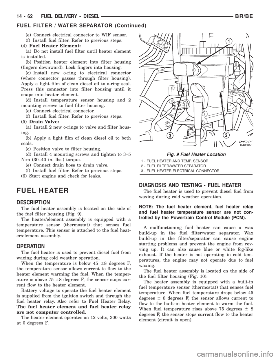
The fuel heater assembly is located on the side of
the fuel filter housing (Fig. 9).
The heater/element assembly is equipped with a
temperature sensor (thermostat) that senses fuel
temperature. This sensor is attached to the fuel heat-
er/element assembly.
OPERATION
The fuel heater is used to prevent diesel fuel from
waxing during cold weather operation.
When the temperature is below 4568 degrees F,
the temperature sensor allows current to flow to the
heater element warming the fuel. When the temper-
ature is above 7568 degrees F, the sensor stops cur-
rent flow to the heater element.
Battery voltage to operate the fuel heater element
is supplied from the ignition switch and through the
fuel heater relay. Also refer to Fuel Heater Relay.
The fuel heater element and fuel heater relay
are not computer controlled.
The heater element operates on 12 volts, 300 watts
at 0 degrees F.
DIAGNOSIS AND TESTING - FUEL HEATER
The fuel heater is used to prevent diesel fuel from
waxing during cold weather operation.
NOTE: The fuel heater element, fuel heater relay
and fuel heater temperature sensor are not con-
trolled by the Powertrain Control Module (PCM).
A malfunctioning fuel heater can cause a wax
build-up in the fuel filter/water separator. Wax
build-up in the filter/separator can cause engine
starting problems and prevent the engine from rev-
ving up. It can also cause blue or white fog-like
exhaust. If the heater is not operating in cold tem-
peratures, the engine may not operate due to fuel
waxing.
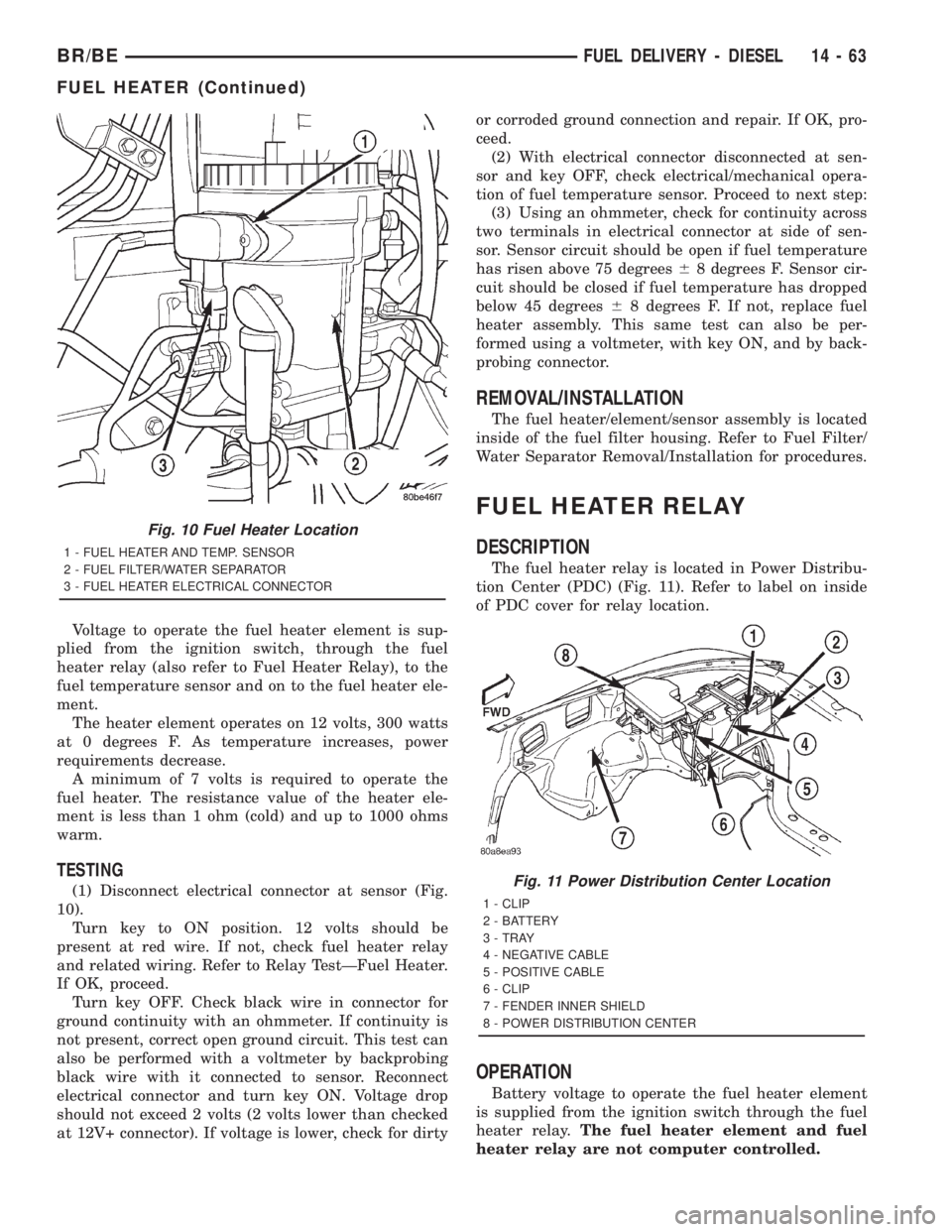
The fuel heater assembly is located on the side of
the fuel filter housing (Fig. 10).
The heater assembly is equipped with a built-in
fuel temperature sensor (thermostat) that senses fuel
temperature. When fuel temperature drops below 45
degrees68 degrees F, the sensor allows current to
flow to the built-in heater element to warm the fuel.
When fuel temperature rises above 75 degrees68
degrees F, the sensor stops current flow to the heater
element (circuit is open).
Fig. 9 Fuel Heater Location
1 - FUEL HEATER AND TEMP. SENSOR
2 - FUEL FILTER/WATER SEPARATOR
3 - FUEL HEATER ELECTRICAL CONNECTOR
14 - 62 FUEL DELIVERY - DIESELBR/BE
FUEL FILTER / WATER SEPARATOR (Continued)
Page 1550 of 2889
Voltage to operate the fuel heater element is sup-
plied from the ignition switch, through the fuel
heater relay (also refer to Fuel Heater Relay), to the
fuel temperature sensor and on to the fuel heater ele-
ment.
The heater element operates on 12 volts, 300 watts
at 0 degrees F. As temperature increases, power
requirements decrease.
A minimum of 7 volts is required to operate the
fuel heater. The resistance value of the heater ele-
ment is less than 1 ohm (cold) and up to 1000 ohms
warm.
TESTING
(1) Disconnect electrical connector at sensor (Fig.
10).
Turn key to ON position. 12 volts should be
present at red wire. If not, check fuel heater relay
and related wiring. Refer to Relay TestÐFuel Heater.
If OK, proceed.
Turn key OFF. Check black wire in connector for
ground continuity with an ohmmeter. If continuity is
not present, correct open ground circuit. This test can
also be performed with a voltmeter by backprobing
black wire with it connected to sensor. Reconnect
electrical connector and turn key ON. Voltage drop
should not exceed 2 volts (2 volts lower than checked
at 12V+ connector). If voltage is lower, check for dirtyor corroded ground connection and repair. If OK, pro-
ceed.
(2) With electrical connector disconnected at sen-
sor and key OFF, check electrical/mechanical opera-
tion of fuel temperature sensor. Proceed to next step:
(3) Using an ohmmeter, check for continuity across
two terminals in electrical connector at side of sen-
sor. Sensor circuit should be open if fuel temperature
has risen above 75 degrees68 degrees F. Sensor cir-
cuit should be closed if fuel temperature has dropped
below 45 degrees68 degrees F. If not, replace fuel
heater assembly. This same test can also be per-
formed using a voltmeter, with key ON, and by back-
probing connector.
REMOVAL/INSTALLATION
The fuel heater/element/sensor assembly is located
inside of the fuel filter housing. Refer to Fuel Filter/
Water Separator Removal/Installation for procedures.
FUEL HEATER RELAY
DESCRIPTION
The fuel heater relay is located in Power Distribu-
tion Center (PDC) (Fig. 11). Refer to label on inside
of PDC cover for relay location.
OPERATION
Battery voltage to operate the fuel heater element
is supplied from the ignition switch through the fuel
heater relay.The fuel heater element and fuel
heater relay are not computer controlled.
Fig. 10 Fuel Heater Location
1 - FUEL HEATER AND TEMP. SENSOR
2 - FUEL FILTER/WATER SEPARATOR
3 - FUEL HEATER ELECTRICAL CONNECTOR
Fig. 11 Power Distribution Center Location
1 - CLIP
2 - BATTERY
3 - TRAY
4 - NEGATIVE CABLE
5 - POSITIVE CABLE
6 - CLIP
7 - FENDER INNER SHIELD
8 - POWER DISTRIBUTION CENTER
BR/BEFUEL DELIVERY - DIESEL 14 - 63
FUEL HEATER (Continued)
Page 1555 of 2889
(1) Remove hose clamp and crankcase vent hose at
crankcase breather (Fig. 17). Remove crankcase
breather from gear cover. Breather threads into
cover.
(2) Remove injection pump nut and washer (Fig.
18). Locate keyway behind washer.
(3) Be sure keyway aligning fuel injection pump
shaft to injection pump gear is in proper position and
pump gear has not slipped on pump shaft.
The following steps will require removing timing
gear cover to gain access to timing gears. Refer to
Group 9, Engines for procedures.
(4) Use a T-type puller to separate injection pump
gear from pump shaft.
(5) Be sure keyway has been installed with arrow
pointed torearof pump (Fig. 19).
(6)Pump timing has been calibrated to pump
keyway. Be sure 3±digit number on pump key-
way (Fig. 19) matches 3±digit number on fuel
injection pump data plate. Plate is located on
side of injection pump (Fig. 20). Twenty±one dif-
ferent calibrated keyways/pumps are available.
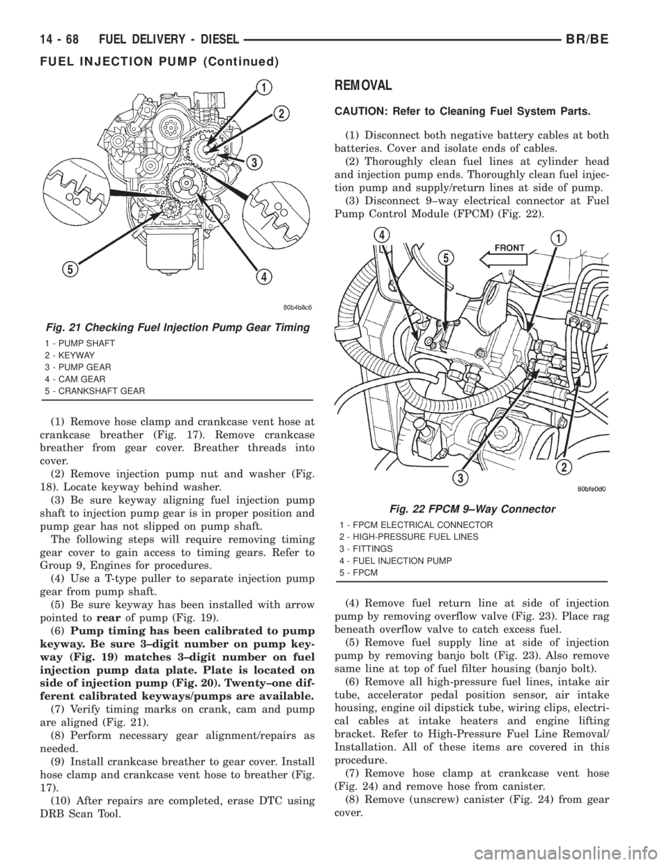
(7) Verify timing marks on crank, cam and pump
are aligned (Fig. 21).
(8) Perform necessary gear alignment/repairs as
needed.
(9) Install crankcase breather to gear cover. Install
hose clamp and crankcase vent hose to breather (Fig.
17).
(10) After repairs are completed, erase DTC using
DRB Scan Tool.
REMOVAL
CAUTION: Refer to Cleaning Fuel System Parts.
(1) Disconnect both negative battery cables at both
batteries. Cover and isolate ends of cables.
(2) Thoroughly clean fuel lines at cylinder head
and injection pump ends. Thoroughly clean fuel injec-
tion pump and supply/return lines at side of pump.
(3) Disconnect 9±way electrical connector at Fuel
Pump Control Module (FPCM) (Fig. 22).
(4) Remove fuel return line at side of injection
pump by removing overflow valve (Fig. 23). Place rag
beneath overflow valve to catch excess fuel.
(5) Remove fuel supply line at side of injection
pump by removing banjo bolt (Fig. 23). Also remove
same line at top of fuel filter housing (banjo bolt).
(6) Remove all high-pressure fuel lines, intake air
tube, accelerator pedal position sensor, air intake
housing, engine oil dipstick tube, wiring clips, electri-
cal cables at intake heaters and engine lifting
bracket. Refer to High-Pressure Fuel Line Removal/
Installation. All of these items are covered in this
procedure.
(7) Remove hose clamp at crankcase vent hose
(Fig. 24) and remove hose from canister.
(8) Remove (unscrew) canister (Fig. 24) from gear
cover.
Fig. 21 Checking Fuel Injection Pump Gear Timing
1 - PUMP SHAFT
2 - KEYWAY
3 - PUMP GEAR
4 - CAM GEAR
5 - CRANKSHAFT GEAR
Fig. 22 FPCM 9±Way Connector
1 - FPCM ELECTRICAL CONNECTOR
2 - HIGH-PRESSURE FUEL LINES
3 - FITTINGS
4 - FUEL INJECTION PUMP
5 - FPCM
14 - 68 FUEL DELIVERY - DIESELBR/BE
FUEL INJECTION PUMP (Continued)
Page 1559 of 2889
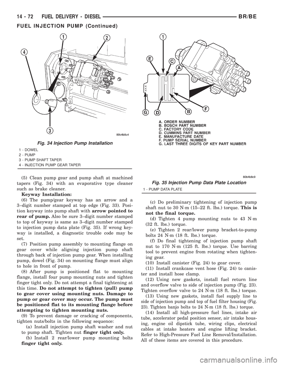
(5) Clean pump gear and pump shaft at machined
tapers (Fig. 34) with an evaporative type cleaner
such as brake cleaner.
Keyway Installation:
(6) The pump/gear keyway has an arrow and a
3±digit number stamped at top edge (Fig. 33). Posi-
tion keyway into pump shaft witharrow pointed to
rear of pump.Also be sure 3±digit number stamped
to top of keyway is same as 3±digit number stamped
to injection pump data plate (Fig. 35). If wrong key-
way is installed, a diagnostic trouble code may be
set.
(7) Position pump assembly to mounting flange on
gear cover while aligning injection pump shaft
through back of injection pump gear. When installing
pump, dowel (Fig. 34) on mounting flange must align
to hole in front of pump.
(8) After pump is positioned flat to mounting
flange, install four pump mounting nuts and tighten
finger tight only. Do not attempt a final tightening at
this time.Do not attempt to tighten (pull) pump
to gear cover using mounting nuts. Damage to
pump or gear cover may occur. The pump must
be positioned flat to its mounting flange before
attempting to tighten mounting nuts.
(9) To prevent damage or cracking of components,
tighten nuts/bolts in the following sequence:
(a) Install injection pump shaft washer and nut
to pump shaft. Tighten nutfinger tight only.
(b) Install 2 rear/lower pump mounting bolts
finger tight only.(c) Do preliminary tightening of injection pump
shaft nut to 30 N´m (15±22 ft. lbs.) torque.This is
not the final torque.
(d) Tighten 4 pump mounting nuts to 43 N´m
(32 ft. lbs.) torque.
(e) Tighten 2 rear/lower pump bracket-to-pump
bolts 24 N´m (18 ft. lbs.) torque.
(f) Do final tightening of injection pump shaft
nut to 170 N´m (125 ft. lbs.) torque. Use barring
tool to prevent engine from rotating when tighten-
ing gear.
(10) Install canister (Fig. 24) to gear cover.
(11) Install crankcase vent hose (Fig. 24) to canis-
ter and install hose clamp.
(12) Using new gaskets, install fuel return line
and overflow valve to side of injection pump (Fig. 23).
Tighten overflow valve to 24 N´m (18 ft. lbs.) torque.
(13)
Using new gaskets, install fuel supply line to
side of injection pump and top of fuel filter housing (Fig.
23). Tighten banjo bolts to 24 N´m (18 ft. lbs.) torque.
(14)Install all high-pressure fuel lines, intake air
tube, accelerator pedal position sensor, air intake hous-
ing, engine oil dipstick tube, wiring clips, electrical
cables at intake heaters and engine lifting bracket.
Refer to High-Pressure Fuel Line Removal/Installation.
All of these items are covered in this procedure.
Fig. 34 Injection Pump Installation
1 - DOWEL
2 - PUMP
3 - PUMP SHAFT TAPER
4 - INJECTION PUMP GEAR TAPER
Fig. 35 Injection Pump Data Plate Location
1 - PUMP DATA PLATE
14 - 72 FUEL DELIVERY - DIESELBR/BE
FUEL INJECTION PUMP (Continued)
Page 1565 of 2889
(3) Installrearinjection line bundle beginning
with cylinder head (fuel injector) connections, fol-
lowed by injection pump connections. Tighten all fit-
tings finger tight.
(4) Tighten fittings at fuel injector ends for cylin-
ders number 6 and 5 to 38 N´m (28 ft. lbs.) torque.
Do not tighten number 3 line at this time. It
will be tightened during bleeding procedure.
(5) Tighten 3 fittings at fuel injection pump ends
to 24 N´m (18 ft. lbs.) torque.
(6) Installfrontinjection line bundle beginning
with cylinder head (fuel injector) connections, fol-
lowed by injection pump connections. Tighten all fit-
tings finger tight.
(7) Tighten fitting at fuel injector end for cylinder
number 2 to 38 N´m (28 ft. lbs.) torque.Do not
tighten lines number 1 or 4 at this time. They
will be tightened during bleeding procedure.
(8) Tighten remaining 3 fittings at fuel injection
pump ends to 24 N´m (18 ft. lbs.) torque.
(9) Install fuel line support bracket bolts to intake
manifold and tighten to 24 N´m (18 ft. lbs.) torque.
CAUTION: Be sure fuel lines are not contacting
each other or any other component. Noise will
result.
(10) Install engine lifting bracket at rear of intake
manifold. Tighten 2 bolts to 77 N´m (57 ft. lbs.)
torque.
(11) Install cable bracket housing/cable assembly
and tighten 3 mounting bolts to 24 N´m (18 ft. lbs.)
torque.
(12) Clean any old gasket material below and
above intake manifold air heater element block. Also
clean mating areas at intake manifold and air intake
housing.
(13) Using new gaskets, position intake manifold
air heater element block to engine.
(14) Install air intake housing and position ground
cable. Install 4 mounting bolts and tighten to 24 N´m
(18 ft. lbs.) torque.
(15) Install air tube (intake manifold-to-charge air
cooler) (Fig. 41). Tighten clamps to 8 N´m (72 in. lbs.)
torque.
(16) Install engine oil dipstick tube support mount-
ing bolt and tighten to 24 N´m (18 ft. lbs.) torque.
(17) Install engine oil dipstick to engine.
(18) Connect 2 electrical cables to cable mounting
studs.
(19) Connect electrical connector to bottom of
APPS by pushing connector upward until it snaps
into position.
(20) Connect wiring harness (clip) at bottom of
Accelerator Pedal Position Sensor (APPS) mounting
bracket (Fig. 40).(21) Connect front wiring clip (Fig. 41) to cable
bracket housing.
(22) Install cable cover (Fig. 39).
(23) Connect both negative battery cables to both
batteries.
(24) Bleed air from fuel system. Do this at fuel
injector ends of lines. Use cylinders numbers 1, 3 and
4 for bleeding . (Refer to 14 - FUEL SYSTEM/FUEL
DELIVERY - STANDARD PROCEDURE). After
bleeding, tighten fittings to 38 N´m (28 ft. lbs.)
torque.
(25) Check lines/fittings for leaks.
FUEL TANK
DESCRIPTION - DIESEL FUEL TANK
The fuel tank is similar to the tank used with gas-
oline powered models. The tank is equipped with a
separate fuel return line and a different fuel tank
module for diesel powered models. A fuel tank
mounted, electric fuel pump is not used with diesel
powered models. Refer to Fuel Tank Module for addi-
tional information.
For removal and installation procedures, refer to
Fuel Tank - Gasoline Engines.
FUEL TANK MODULE
DESCRIPTION
An electric fuel pump isnot usedin the fuel tank
module for diesel powered engines. Fuel is supplied
by the engine mounted fuel transfer pump and the
fuel injection pump.
The fuel tank module is installed in the top of the
fuel tank (Fig. 48). The fuel tank module (Fig. 48)
contains the following components:
²Fuel reservoir
²A separate in-tank fuel filter
²Rollover valve
²Fuel gauge sending unit (fuel level sensor)
²Fuel supply line connection
²Fuel return line connection
²Auxiliary non-pressurized fuel supply fitting
OPERATION
Refer to Fuel Gauge Sending Unit.
REMOVAL
(1) Drain and remove fuel tank. Refer to Fuel
Tank Removal/Installation.
(2) Thoroughly clean area around tank module at
top of tank.
14 - 78 FUEL DELIVERY - DIESELBR/BE
FUEL LINES (Continued)
Page 1566 of 2889
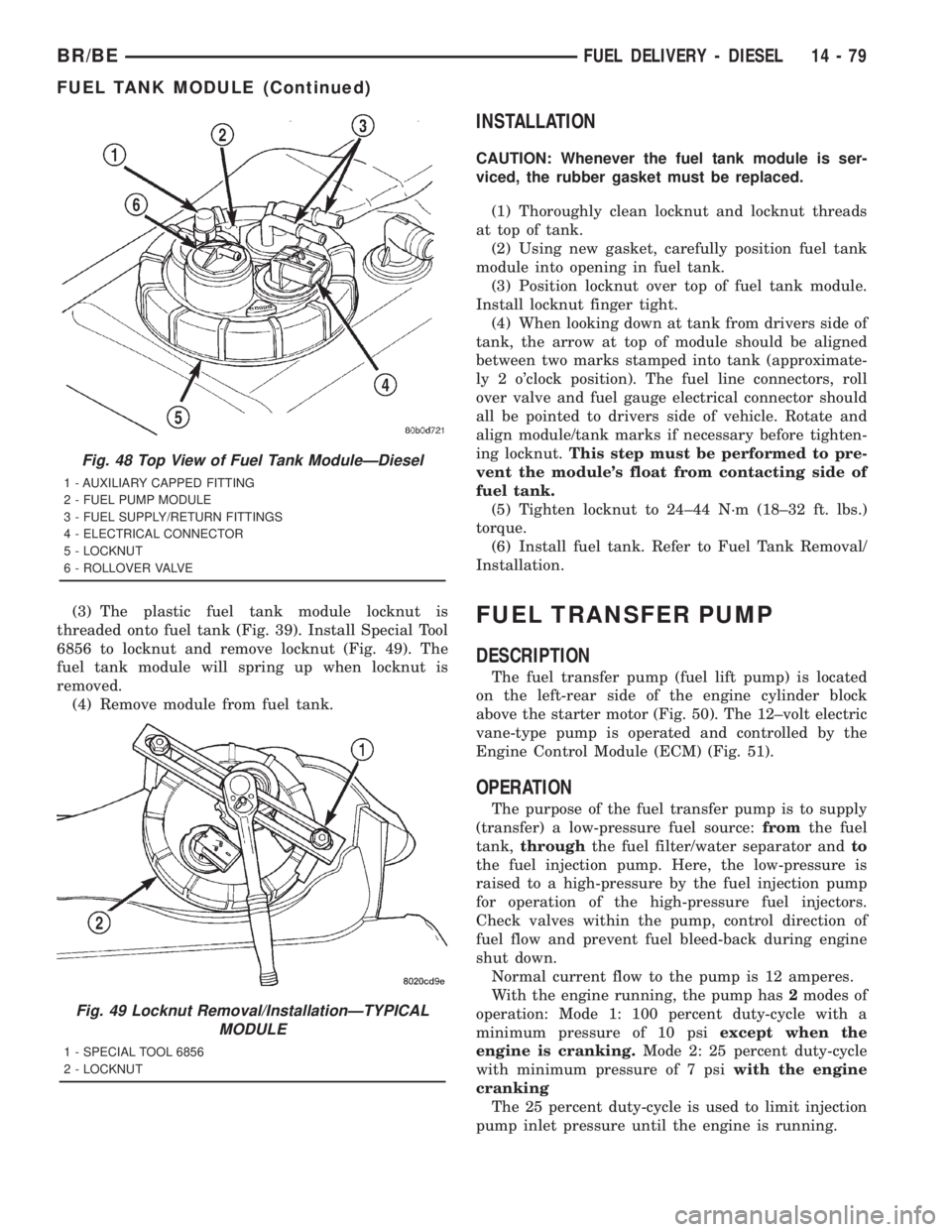
(3) The plastic fuel tank module locknut is
threaded onto fuel tank (Fig. 39). Install Special Tool
6856 to locknut and remove locknut (Fig. 49). The
fuel tank module will spring up when locknut is
removed.
(4) Remove module from fuel tank.
INSTALLATION
CAUTION: Whenever the fuel tank module is ser-
viced, the rubber gasket must be replaced.
(1) Thoroughly clean locknut and locknut threads
at top of tank.
(2) Using new gasket, carefully position fuel tank
module into opening in fuel tank.
(3) Position locknut over top of fuel tank module.
Install locknut finger tight.
(4) When looking down at tank from drivers side of
tank, the arrow at top of module should be aligned
between two marks stamped into tank (approximate-
ly 2 o'clock position). The fuel line connectors, roll
over valve and fuel gauge electrical connector should
all be pointed to drivers side of vehicle. Rotate and
align module/tank marks if necessary before tighten-
ing locknut.This step must be performed to pre-
vent the module's float from contacting side of
fuel tank.
(5) Tighten locknut to 24±44 N´m (18±32 ft. lbs.)
torque.
(6) Install fuel tank. Refer to Fuel Tank Removal/
Installation.
FUEL TRANSFER PUMP
DESCRIPTION
The fuel transfer pump (fuel lift pump) is located
on the left-rear side of the engine cylinder block
above the starter motor (Fig. 50). The 12±volt electric
vane-type pump is operated and controlled by the
Engine Control Module (ECM) (Fig. 51).
OPERATION
The purpose of the fuel transfer pump is to supply
(transfer) a low-pressure fuel source:fromthe fuel
tank,throughthe fuel filter/water separator andto
the fuel injection pump. Here, the low-pressure is
raised to a high-pressure by the fuel injection pump
for operation of the high-pressure fuel injectors.
Check valves within the pump, control direction of
fuel flow and prevent fuel bleed-back during engine
shut down.
Normal current flow to the pump is 12 amperes.
With the engine running, the pump has2modes of
operation: Mode 1: 100 percent duty-cycle with a
minimum pressure of 10 psiexcept when the
engine is cranking.Mode 2: 25 percent duty-cycle
with minimum pressure of 7 psiwith the engine
cranking
The 25 percent duty-cycle is used to limit injection
pump inlet pressure until the engine is running.
Fig. 48 Top View of Fuel Tank ModuleÐDiesel
1 - AUXILIARY CAPPED FITTING
2 - FUEL PUMP MODULE
3 - FUEL SUPPLY/RETURN FITTINGS
4 - ELECTRICAL CONNECTOR
5 - LOCKNUT
6 - ROLLOVER VALVE
Fig. 49 Locknut Removal/InstallationÐTYPICAL
MODULE
1 - SPECIAL TOOL 6856
2 - LOCKNUT
BR/BEFUEL DELIVERY - DIESEL 14 - 79
FUEL TANK MODULE (Continued)