2001 CHRYSLER VOYAGER tow
[x] Cancel search: towPage 1922 of 4284
IGNITION COIL
DESCRIPTION
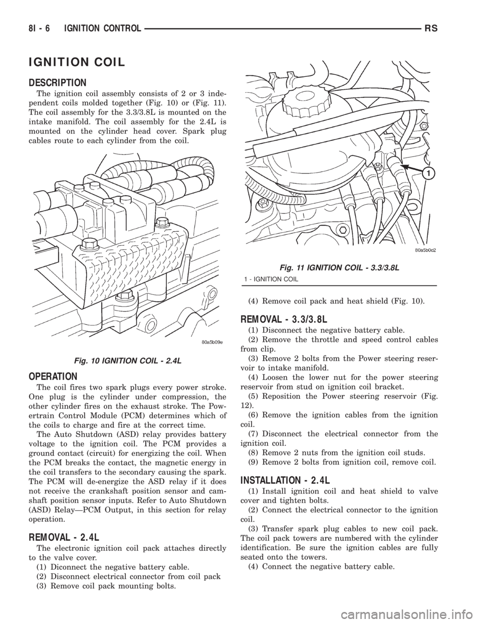
The ignition coil assembly consists of 2 or 3 inde-
pendent coils molded together (Fig. 10) or (Fig. 11).
The coil assembly for the 3.3/3.8L is mounted on the
intake manifold. The coil assembly for the 2.4L is
mounted on the cylinder head cover. Spark plug
cables route to each cylinder from the coil.
OPERATION
The coil fires two spark plugs every power stroke.
One plug is the cylinder under compression, the
other cylinder fires on the exhaust stroke. The Pow-
ertrain Control Module (PCM) determines which of
the coils to charge and fire at the correct time.
The Auto Shutdown (ASD) relay provides battery
voltage to the ignition coil. The PCM provides a
ground contact (circuit) for energizing the coil. When
the PCM breaks the contact, the magnetic energy in
the coil transfers to the secondary causing the spark.
The PCM will de-energize the ASD relay if it does
not receive the crankshaft position sensor and cam-
shaft position sensor inputs. Refer to Auto Shutdown
(ASD) RelayÐPCM Output, in this section for relay
operation.
REMOVAL - 2.4L
The electronic ignition coil pack attaches directly
to the valve cover.
(1) Diconnect the negative battery cable.
(2) Disconnect electrical connector from coil pack
(3) Remove coil pack mounting bolts.(4) Remove coil pack and heat shield (Fig. 10).
REMOVAL - 3.3/3.8L
(1) Disconnect the negative battery cable.
(2) Remove the throttle and speed control cables
from clip.
(3) Remove 2 bolts from the Power steering reser-
voir to intake manifold.
(4) Loosen the lower nut for the power steering
reservoir from stud on ignition coil bracket.
(5) Reposition the Power steering reservoir (Fig.
12).
(6) Remove the ignition cables from the ignition
coil.
(7) Disconnect the electrical connector from the
ignition coil.
(8) Remove 2 nuts from the ignition coil studs.
(9) Remove 2 bolts from ignition coil, remove coil.
INSTALLATION - 2.4L
(1) Install ignition coil and heat shield to valve
cover and tighten bolts.
(2) Connect the electrical connector to the ignition
coil.
(3) Transfer spark plug cables to new coil pack.
The coil pack towers are numbered with the cylinder
identification. Be sure the ignition cables are fully
seated onto the towers.
(4) Connect the negative battery cable.
Fig. 10 IGNITION COIL - 2.4L
Fig. 11 IGNITION COIL - 3.3/3.8L
1 - IGNITION COIL
8I - 6 IGNITION CONTROLRS
Page 1955 of 4284
OPERATION - TURN SIGNAL SYSTEM
Lane change signaling is actuated by applying par-
tial turn signal stalk movement toward the direction
desired until the indicator lamps flashes in the
instrument cluster. When the switch stalk is released
the stalk will spring back into the neutral position
turning OFF the turn signal.
With the ignition switch ON and the turn signal
switch stalk actuated left or right, current flows
through the:
²Multi-function switch
²Body Control Module
²Integrated Power Module (IPM)
²Turn indicator lamp
²Front and rear turn signal bulbs.
A chime will sound after the vehicle has traveled a
distance of approximately 0.5 mile and a speed of 15
mph, with the turn signal ON.
DIAGNOSIS AND TESTING - MULTI-FUNCTION
SWITCH
To test turn signal, headlamp beam select and opti-
cal horn portion of the multi-function switch:
(1) Remove the multi-function switch, refer to
Electrical, Lamps/Lighting - Exterior, Multi-Function
Switch, Removal, and Installation.
(2) Using an ohmmeter check the continuity read-
ings between multi-function switch pins. Refer to
Wiring Diagrams for proper pin numbers and the
table.
MULTI-FUNCTION SWITCH CONTINUITY
SWITCH POSITION CONTINUITY BETWEEN
LEFT 2 AND 3
RIGHT 2 AND 3
OPTICAL HORN 2 AND 4
HI BEAM 2 AND 4
REMOVAL
(1) Disconnect and isolate battery negative cable.
(2) Remove upper and lower steering column
shrouds. Refer to Steering, Column, Shroud,
Removal.
(3) Disconnect wire connector from back of multi-
function switch.
(4) Remove screws holding multi-function switch to
steering column adapter collar.
(5) Remove the multi-function switch.
INSTALLATION
(1) Position the switch on to the steering column.
(2) Install the two retaining screws.
(3) Connect the wire harness connector.
(4) Install the upper and lower steering column
shrouds. Refer to Steering, Column, Shroud, Installa-
tion.
(5) Connect the battery negative cable.
PARK/TURN SIGNAL LAMP
REMOVAL
(1) Disconnect and isolate battery negative cable.
(2) Remove headlamp retaining screws.
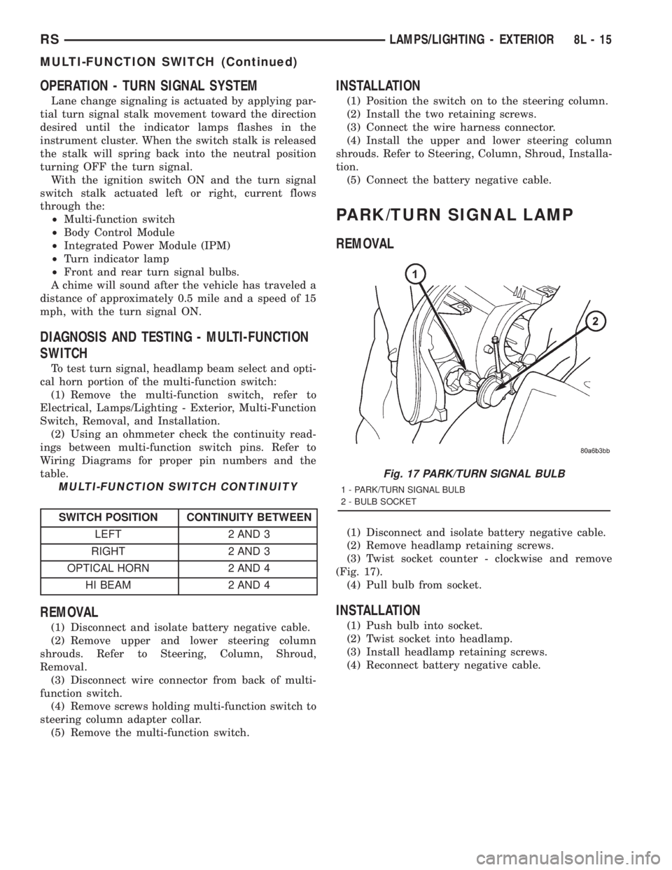
(3) Twist socket counter - clockwise and remove
(Fig. 17).
(4) Pull bulb from socket.
INSTALLATION
(1) Push bulb into socket.
(2) Twist socket into headlamp.
(3) Install headlamp retaining screws.
(4) Reconnect battery negative cable.
Fig. 17 PARK/TURN SIGNAL BULB
1 - PARK/TURN SIGNAL BULB
2 - BULB SOCKET
RSLAMPS/LIGHTING - EXTERIOR8L-15
MULTI-FUNCTION SWITCH (Continued)
Page 2012 of 4284
LEFT B-PILLAR SWITCH
DESCRIPTION
Vehicles equipped with power sliding side door/s
utilize B-pillar switches. These switches are located
on the interior of the vehicle, on the B-pillar trim
panels. These switches serve as an open and close
command switch for the appropriate power side door.
The B-pillar switches are replaceable. Consult your
Mopar parts catalog for a specific part number.
OPERATION
When the Pillar switch is depressed a signal is
sent to the Body Control Module (BCM), this signal
is then sent to the Power Sliding Door Module, tell-
ing it to start a power open or close cycle. The child
lockout feature must be disabled and the side door
must be unlocked in order for the Pillar switch to
function.
REMOVAL
(1) Disconnect and isolate the negative battery
cable.
(2) Using a trim stick or other small flat-bladed
pry tool, gently pry the leading upper edge of the
B-pillar switch away from the B-pillar trim.
(3) Once the upper edge is free from pillar trim,
rock the switch out of the switch opening.
(4) Disconnect the B-pillar switch electrical con-
nector. First, slide the connector lock away from the
switch then, depress connector retaining tab while
pulling straight apart.
(5) Remove the B-pillar switch from the vehicle.
INSTALLATION
(1) Connect the B-pillar switch electrical connector.
Slide connector lock toward the switch to lock in
place.
(2) Hook the lower edge of the B-pillar switch on
the B-pillar trim and then push the switch firmly
into position.
(3) Connect the negative battery cable.
RIGHT B-PILLAR SWITCH
DESCRIPTION
Vehicles equipped with power sliding side door/s
utilize B-pillar switches. These switches are located
on the interior of the vehicle, on the B-pillar trim
panels. These switches serve as an open and close
command switch for the appropriate power side door.
The B-pillar switches are replaceable. Consult your
Mopar parts catalog for a specific part number.
OPERATION
When the Pillar switch is depressed a signal is
sent to the Body Control Module (BCM), this signal
is then sent to the Power Sliding Door Module, tell-
ing it to start a power open or close cycle. The child
lockout feature must be disabled and the side door
must be unlocked in order for the Pillar switch to
function.
REMOVAL
(1) Disconnect and isolate the negative battery
cable.
(2) Using a trim stick or other small flat-bladed
pry tool, gently pry the leading upper edge of the
B-pillar switch away from the B-pillar trim.
(3) Once the upper edge is free from pillar trim,
rock the switch out of the switch opening.
(4) Disconnect the B-pillar switch electrical con-
nector. First, slide the connector lock away from the
switch then, depress connector retaining tab while
pulling straight apart.
(5) Remove the B-pillar switch from the vehicle.
INSTALLATION
(1) Connect the B-pillar switch electrical connector.
Slide connector lock toward the switch to lock in
place.
(2) Hook the lower edge of the B-pillar switch on
the B-pillar trim and then push the switch firmly
into position.
(3) Connect the negative battery cable.
8N - 32 POWER SLIDING DOOR SYSTEMRS
Page 2022 of 4284
REMOVAL
(1) Disconnect and isolate the battery negative
cable.
(2) Remove door trim panel. Refer to Body, Door -
Front, Trim Panel, Removal.
(3) Disconnect wire connector from back of door
lock switch.
(4) Remove two screws to door lock switch.
(5) Remove switch from vehicle.
INSTALLATION
(1) Install the switch into the vehicle.
(2) Install the two screws to door lock switch.
(3) Connect wire connector to back of door lock
switch.
(4) Install door trim panel. Refer to Body, Door -
Front, Trim Panel, Installation.
(5) Connect the battery negative cable.
KEYLESS ENTRY
TRANSMITTER
STANDARD PROCEDURE - HORN CHIRP
PREFERENCE
DISABLING
The horn chirp can be toggled using a DRB IIItor
by using the Remote Keyless Entry (RKE) transmit-
ter.
To DISABLE (cancelling) the horn chirp feature,
press and hold the transmitter LOCK button for a
minimum of four seconds. While pressing the LOCK
button in, press the UNLOCK button. The horn chirp
feature will not function until the above procedure is
repeated.
ENABLING
The horn chirp can be toggled using a DRB IIItor
by using the Remote Keyless Entry (RKE) transmit-
ter.
To ENABLE (reinstate) the horn chirp feature, use
any one of the four key fob transmitters and reverse
the above procedures. It will ENABLE the horn chirp
feature for all transmitters.
STANDARD PROCEDURE - BATTERY
REPLACEMENT
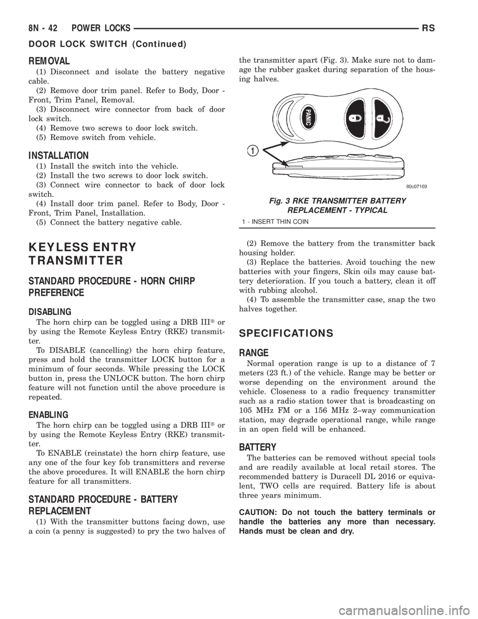
(1) With the transmitter buttons facing down, use
a coin (a penny is suggested) to pry the two halves ofthe transmitter apart (Fig. 3). Make sure not to dam-
age the rubber gasket during separation of the hous-
ing halves.
(2) Remove the battery from the transmitter back
housing holder.
(3) Replace the batteries. Avoid touching the new
batteries with your fingers, Skin oils may cause bat-
tery deterioration. If you touch a battery, clean it off
with rubbing alcohol.
(4) To assemble the transmitter case, snap the two
halves together.
SPECIFICATIONS
RANGE
Normal operation range is up to a distance of 7
meters (23 ft.) of the vehicle. Range may be better or
worse depending on the environment around the
vehicle. Closeness to a radio frequency transmitter
such as a radio station tower that is broadcasting on
105 MHz FM or a 156 MHz 2±way communication
station, may degrade operational range, while range
in an open field will be enhanced.
BATTERY
The batteries can be removed without special tools
and are readily available at local retail stores. The
recommended battery is Duracell DL 2016 or equiva-
lent, TWO cells are required. Battery life is about
three years minimum.
CAUTION: Do not touch the battery terminals or
handle the batteries any more than necessary.
Hands must be clean and dry.
Fig. 3 RKE TRANSMITTER BATTERY
REPLACEMENT - TYPICAL
1 - INSERT THIN COIN
8N - 42 POWER LOCKSRS
DOOR LOCK SWITCH (Continued)
Page 2034 of 4284
(7) Remove the power seat switch from the out-
board seat cushion side shield.
INSTALLATION
(1) Position the power seat switch onto the out-
board seat cushion side shield.
(2) Install and tighten the screws that secure the
power seat switch to the inside of the outboard seat
cushion side shield. Tighten the screws to 1.5 N´m
(14 in. lbs.).
(3) Reconnect the power seat wire harness connec-
tor to the power seat switch connector receptacle.
(4) Position the outboard seat cushion side shield
onto the seat cushion frame
(5) Install and tighten the screws that secure the
outboard seat cushion side shield to the seat cushion
frame. Tighten the screws to 1.5 N´m (14 in. lbs.).
(6) Reconnect the battery negative cable.
MEMORY SET SWITCH
DESCRIPTION
Vehicles equipped with the memory system have a
memory switch mounted to the driver side front door
trim panel. This switch is used to set and recall all of
the memory system settings for up to two drivers.
The memory switch is a resistor multiplexed unit
that is hard wired to the Body Control Module
(BCM). The BCM sends out the memory system set
and recall requests to the other electronic modules
over the Programmable Communications Interface
(PCI) data bus.
The memory switch cannot be adjusted or repaired
and, if faulty or damaged, it must be replaced. For
complete circuit diagrams, refer toWiring Dia-
grams.
OPERATION
The memory switch has three momentary switch
buttons labeled Set, 1 and 2. The Driver 1 and Driver
2 buttons are back-lit with Light-Emitting Diodes
(LED) for visibility, and are also color-coded to coin-
cide with the color-coded Driver 1 and Driver 2
Remote Keyless Entry (RKE) transmitters. The
Driver 1 memory switch button and RKE transmitter
are black, and the Driver 2 memory switch button
and RKE transmitter are gray. The memory switch
Set button also has an LED that will illuminate and
flash to indicate that the memory system is in the set
mode. This LED will automatically be extinguished
when a set request has been successfully completed.
See the owner's manual in the vehicle glove box for
more information on the features, use and operation
of the memory switch.
DIAGNOSIS AND TESTING - MEMORY SWITCH
For complete circuit diagrams, refer toWiring
Diagrams.
(1) Disconnect and isolate the battery negative
cable.
(2) Remove the driver side front door trim panel
switch bezel. Using a small thin bladed pry tool, gen-
tly pry the switch bezel away from the door trim
panel.
(3) Disconnect the memory switch wire harness
connector from the memory switch.
(4) Use an ohmmeter to test the resistances of the
memory switch in each switch position. See the Mem-
ory Switch Test chart. If OK, refer toMemory Sys-
temin the Diagnosis and Testing section of this
group. If not OK, replace the faulty memory switch.
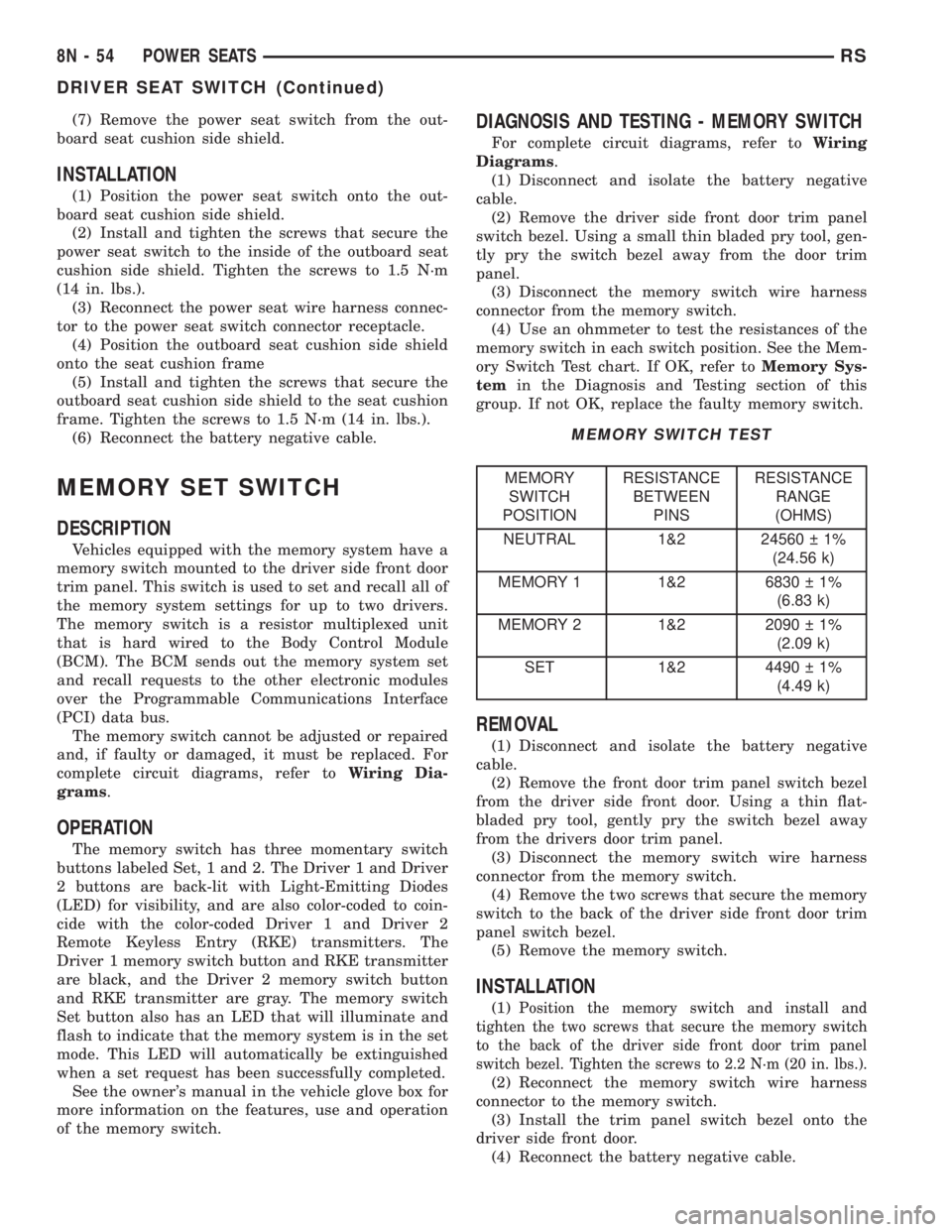
MEMORY SWITCH TEST
MEMORY
SWITCH
POSITIONRESISTANCE
BETWEEN
PINSRESISTANCE
RANGE
(OHMS)
NEUTRAL 1&2 24560 1%
(24.56 k)
MEMORY 1 1&2 6830 1%
(6.83 k)
MEMORY 2 1&2 2090 1%
(2.09 k)
SET 1&2 4490 1%
(4.49 k)
REMOVAL
(1) Disconnect and isolate the battery negative
cable.
(2) Remove the front door trim panel switch bezel
from the driver side front door. Using a thin flat-
bladed pry tool, gently pry the switch bezel away
from the drivers door trim panel.
(3) Disconnect the memory switch wire harness
connector from the memory switch.
(4) Remove the two screws that secure the memory
switch to the back of the driver side front door trim
panel switch bezel.
(5) Remove the memory switch.
INSTALLATION
(1)Position the memory switch and install and
tighten the two screws that secure the memory switch
to the back of the driver side front door trim panel
switch bezel. Tighten the screws to 2.2 N´m (20 in. lbs.).
(2) Reconnect the memory switch wire harness
connector to the memory switch.
(3) Install the trim panel switch bezel onto the
driver side front door.
(4) Reconnect the battery negative cable.
8N - 54 POWER SEATSRS
DRIVER SEAT SWITCH (Continued)
Page 2050 of 4284
(4) Remove steering wheel.
(5) Depress the two plastic locking pins to disen-
gage lock mechanism.
(6) With lock mechanism disengaged, rotate the
clock spring rotor clockwise until the rotor stops. Do
not apply excessive force.
(7) From the end of travel, rotate the rotor three
turns counterclockwise. The wires should end up at
the top. Release locking pins to engage clock spring
lock mechanism.
(8) Install steering wheel and airbag.
WARNING: DO NOT CONNECT THE BATTERY NEG-
ATIVE CABLE. REFER TO ELECTRICAL,
RESTRAINTS, DIAGNOSIS AND TESTING - AIRBAG
SYSTEM FIRST.
REMOVAL
(1) Position steering wheel and front wheels
straight ahead.
(2) Release hood latch and open hood. Disconnect
and isolate the battery negative cable.
(3) Remove driver airbag from steering wheel.
(4) Disconnect wire connectors from back of driver
airbag.
(5) Disconnect the 2±way connector from remote
radio control harness.
(6) Remove steering wheel.
(7) Remove steering column shrouds.
(8) Disconnect 2-way and 5-way connectors
between the clock spring and the instrument panel
wiring harness.
(9) Remove clock spring from housing assembly by
removing the two retaining screws retaining the
clock spring.
INSTALLATION
(1) Position the clock spring into the housing.
Install the two retaining screws to clock spring.
(2) Connect the two way and five way harness
between the clock spring and the instrument panel.
(3) Install the steering wheel. Refer to Steering,
Column, Steering Wheel, Installation.
(4) Connect the harness connector to the driver
airbag.
(5) Connect the remote radio control harness.
(6)
Install the driver airbag into the steering wheel.
(7) Install the steering column upper and lower
shrouds.
WARNING: DO NOT CONNECT THE BATTERY NEG-
ATIVE CABLE. REFER TO ELECTRICAL,
RESTRAINTS, DIAGNOSIS AND TESTING - AIRBAG
SYSTEM FIRST.
DRIVER AIRBAG
DESCRIPTION
The Driver Airbag is located in the center of the
steering wheel. The most visible part of the airbag is
the cover/horn switch.
OPERATION
The Driver Airbag cover contains the horn switch,
inflator device, and a fabric bag. The airbag cover/
horn switch is serviced separately from the inflator
and bag components.
WHEN THE FRONT AIRBAG SYSTEM IS
DEPLOYED BECAUSE OF A COLLISION, THE
FOLLOWING MUST BE REPLACED:
²COMPLETE STEERING COLUMN ASSEMBLY
²LOWER STEERING COUPLER
²STEERING WHEEL
²STEERING COLUMN CLOCK SPRING
²DRIVER AIRBAG
²PASSENGER AIRBAG
²UPPER INSTRUMENT PANEL WITH PAD
CARE OF UNDEPLOYED AIRBAGS
Airbags must be stored in their original special
container until used for service. At no time should a
source of electricity be permitted near the inflator on
the back of an airbag. When carrying or handling an
undeployed airbag, the trim side of the airbag should
be pointing away from the body to minimize possibil-
ity of injury if accidental deployment occurs. Do not
place undeployed airbag face down on a solid surface,
the airbag will propel into the air if accidental
deployment occurs.
STANDARD PROCEDURE - DEPLOYED DRIVER
AIRBAG CLEAN UP
Roll or fold the driver airbag towards the steering
wheel and then tape the bag to the steering wheel.
Use a vacuum cleaner to remove any residual pow-
der from the vehicle interior. Work from the outside
in to avoid kneeling or sitting in a contaminated
area. Vacuum the heater and A/C outlets as well. If
HVAC was in RECIRC mode at time of airbag
deployment, operate HVAC blower on low speed/heat
and vacuum powder residue expelled from the heat
outlets. Multiple vacuum cleaning may be necessary
to decontaminate the interior of the vehicle.
SERVICE OF DEPLOYED AIRBAG
If a Driver Airbag has been deployed, but not due
to a collision, replace the following:
²Driver Airbag
²Clock Spring Assembly
8O - 4 RESTRAINTSRS
CLOCK SPRING (Continued)
Page 2052 of 4284
CAUTION: Use correct screws when installing the
ORC.
(1) Install the ORC assembly into vehicle.
(2) Connect the wire connector to the ORC.
(3) Install three bolts holding ORC to floor
bracket. Torque bolts to 7.3 - 9.6 N´m (65 to 85 in.
lbs.)
(4) Install the storage bin onto the instrument
panel. Refer to Body, Instrument Panel, Storage Bin,
Installation.
WARNING: DO NOT CONNECT THE BATTERY NEG-
ATIVE CABLE. REFER TO ELECTRICAL,
RESTRAINTS, DIAGNOSIS AND TESTING - AIRBAG
SYSTEM FIRST.
PASSENGER AIRBAG
DESCRIPTION
WARNING: NEVER DISASSEMBLE THE PASSEN-
GER AIRBAG, THE PASSENGER AIRBAG HAS NO
SERVICEABLE PARTS.
The Passenger Airbag is located beneath the
instrument panel and pad assembly. The airbag is
mounted to the back side of the instrument panel
reinforcement.
The instrument panel top pad is the most visible
part of the passenger airbag system. Located under
the instrument panel top pad are the airbag door, the
passenger airbag cushion and the airbag cushion
supporting components.
The passenger airbag includes a magnesium hous-
ing within which the cushion and inflator are
mounted and sealed.
Following a passenger airbag deployment, the pas-
senger airbag and the instrument panel must be
replaced. The passenger airbag cannot be repaired,
and must be replaced if deployed or damaged in any
way.
OPERATION
The passenger airbag is equipped with two infla-
tors, each with three levels of pressure output. The
inflators seal the hole in the airbag cushion so it can
discharge the gas it produces directly into the cush-
ion when supplied with the proper electrical signal.
Following an airbag deployment, the airbag cushion
quickly deflates by venting this gas through the
cushion material towards the instrument panel.
The passenger airbag is secured with screws to the
instrument panel beneath the instrument panel top
pad and above the glove box opening. The instrumentpanel top pad above the glove box opening conceals
the airbag door and a predetermined hinge line
beneath its decorative cover. Upon airbag deploy-
ment, the top pad will bend at the hinge line and the
door will fold back out of the way onto the top of the
instrument panel.
WHEN THE FRONT AIRBAG SYSTEM IS
DEPLOYED BECAUSE OF A COLLISION, THE
FOLLOWING MUST BE REPLACED:
²COMPLETE STEERING COLUMN ASSEMBLY
²LOWER STEERING COUPLER
²STEERING WHEEL
²STEERING COLUMN CLOCK SPRING
²DRIVER AIRBAG COVER/HORN SWITCH
²DRIVER AIRBAG
²PASSENGER AIRBAG
²UPPER INSTRUMENT PANEL WITH PAD
CARE OF UNDEPLOYED AIRBAGS
Airbags must be stored in their original special
container until used for service. At no time should a
source of electricity be permitted near the inflator on
the back of an airbag. When carrying or handling an
undeployed airbag, the trim side of the airbag should
be pointing away from the body to minimize possibil-
ity of injury if accidental deployment occurs. Do not
place undeployed airbag face down on a solid surface,
the airbag will propel into the air if accidental
deployment occurs.
STANDARD PROCEDURE - DEPLOYED
PASSENGER AIRBAG CLEAN UP
Roll or fold the passenger airbag towards the
instrument panel surface and close the door over the
folded bag. Then tape the door shut.
Use a vacuum cleaner to remove any residual pow-
der from the vehicle interior. Work from the outside
in to avoid kneeling or sitting in a contaminated
area. Vacuum the heater and A/C outlets as well. If
HVAC was in RECIRC mode at time of airbag
deployment, operate HVAC blower on low speed/heat
and vacuum powder residue expelled from the heat
outlets. Multiple vacuum cleaning may be necessary
to decontaminate the interior of the vehicle.
SERVICE OF DEPLOYED AIRBAG
If a Passenger Airbag has been deployed, but not
due to a collision, replace the following:
²Passenger Airbag
²Upper instrument panel with pad
The component above must be replaced because
they cannot be reused. Inspect the heat duct near the
passenger airbag for any damage replace as neces-
sary. Replace any other passenger airbag system
components if damaged.
8O - 6 RESTRAINTSRS
OCCUPANT RESTRAINT CONTROLLER (Continued)
Page 2085 of 4284
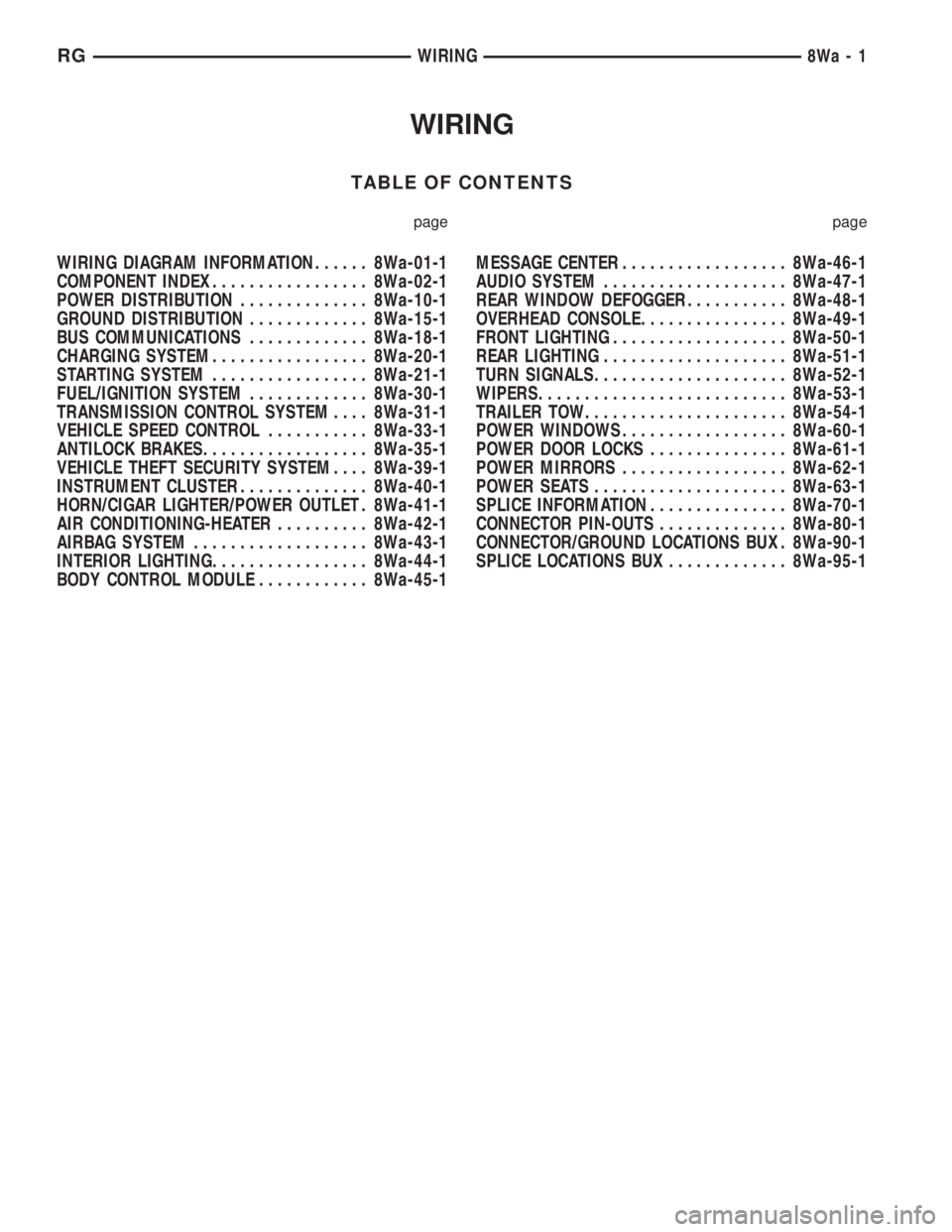
WIRING
TABLE OF CONTENTS
page page
WIRING DIAGRAM INFORMATION...... 8Wa-01-1
COMPONENT INDEX................. 8Wa-02-1
POWER DISTRIBUTION.............. 8Wa-10-1
GROUND DISTRIBUTION............. 8Wa-15-1
BUS COMMUNICATIONS............. 8Wa-18-1
CHARGING SYSTEM................. 8Wa-20-1
STARTING SYSTEM................. 8Wa-21-1
FUEL/IGNITION SYSTEM............. 8Wa-30-1
TRANSMISSION CONTROL SYSTEM.... 8Wa-31-1
VEHICLE SPEED CONTROL........... 8Wa-33-1
ANTILOCK BRAKES.................. 8Wa-35-1
VEHICLE THEFT SECURITY SYSTEM.... 8Wa-39-1
INSTRUMENT CLUSTER.............. 8Wa-40-1
HORN/CIGAR LIGHTER/POWER OUTLET . 8Wa-41-1
AIR CONDITIONING-HEATER.......... 8Wa-42-1
AIRBAG SYSTEM................... 8Wa-43-1
INTERIOR LIGHTING................. 8Wa-44-1
BODY CONTROL MODULE............ 8Wa-45-1MESSAGE CENTER.................. 8Wa-46-1
AUDIO SYSTEM.................... 8Wa-47-1
REAR WINDOW DEFOGGER........... 8Wa-48-1
OVERHEAD CONSOLE................ 8Wa-49-1
FRONT LIGHTING................... 8Wa-50-1
REAR LIGHTING.................... 8Wa-51-1
TURN SIGNALS..................... 8Wa-52-1
WIPERS........................... 8Wa-53-1
TRAILER TOW...................... 8Wa-54-1
POWER WINDOWS.................. 8Wa-60-1
POWER DOOR LOCKS............... 8Wa-61-1
POWER MIRRORS.................. 8Wa-62-1
POWER SEATS..................... 8Wa-63-1
SPLICE INFORMATION............... 8Wa-70-1
CONNECTOR PIN-OUTS.............. 8Wa-80-1
CONNECTOR/GROUND LOCATIONS BUX . 8Wa-90-1
SPLICE LOCATIONS BUX............. 8Wa-95-1 RGWIRING
8Wa-1