2001 CHRYSLER VOYAGER tow
[x] Cancel search: towPage 2704 of 4284
when applying form-in-place gaskets to assure
obtaining the desired results.Do not use form-in-
place gasket material unless specified.Bead size,
continuity, and location are of great importance. Too
thin a bead can result in leakage while too much can
result in spill-over which can break off and obstruct
fluid feed lines. A continuous bead of the proper
width is essential to obtain a leak-free gasket.
There are numerous types of form-in-place gasket
materials that are used in the engine area. Mopart
Engine RTV GEN II, MopartATF-RTV, and Mopart
Gasket Maker gasket materials, each have different
properties and can not be used in place of the other.
MOPARtENGINE RTV GEN IIis used to seal
components exposed to engine oil. This material is a
specially designed black silicone rubber RTV that
retains adhesion and sealing properties when
exposed to engine oil. Moisture in the air causes the
material to cure. This material is available in three
ounce tubes and has a shelf life of one year. After one
year this material will not properly cure. Always
inspect the package for the expiration date before
use.
MOPARtATF RTVis a specifically designed
black silicone rubber RTV that retains adhesion and
sealing properties to seal components exposed to
automatic transmission fluid, engine coolants, and
moisture. This material is available in three ounce
tubes and has a shelf life of one year. After one year
this material will not properly cure. Always inspect
the package for the expiration date before use.
MOPARtGASKET MAKERis an anaerobic type
gasket material. The material cures in the absence of
air when squeezed between two metallic surfaces. It
will not cure if left in the uncovered tube. The
anaerobic material is for use between two machined
surfaces. Do not use on flexible metal flanges.
MOPARtBED PLATE SEALANTis a unique
(green-in-color) anaerobic type gasket material that
is specially made to seal the area between the bed-
plate and cylinder block without disturbing the bear-
ing clearance or alignment of these components. The
material cures slowly in the absence of air when
torqued between two metallic surfaces, and will rap-
idly cure when heat is applied.
MOPARtGASKET SEALANTis a slow drying,
permanently soft sealer. This material is recom-
mended for sealing threaded fittings and gaskets
against leakage of oil and coolant. Can be used on
threaded and machined parts under all tempera-
tures. This material is used on engines with multi-
layer steel (MLS) cylinder head gaskets. This
material also will prevent corrosion. MopartGasket
Sealant is available in a 13 oz. aerosol can or 4oz./16
oz. can w/applicator.SEALER APPLICATION
MopartGasket Maker material should be applied
sparingly 1 mm (0.040 in.) diameter or less of sealant
to one gasket surface. Be certain the material sur-
rounds each mounting hole. Excess material can eas-
ily be wiped off. Components should be torqued in
place within 15 minutes. The use of a locating dowel
is recommended during assembly to prevent smear-
ing material off the location.
MopartEngine RTV GEN II or ATF RTV gasket
material should be applied in a continuous bead
approximately 3 mm (0.120 in.) in diameter. All
mounting holes must be circled. For corner sealing, a
3.17 or 6.35 mm (1/8 or 1/4 in.) drop is placed in the
center of the gasket contact area. Uncured sealant
may be removed with a shop towel. Components
should be torqued in place while the sealant is still
wet to the touch (within 10 minutes). The usage of a
locating dowel is recommended during assembly to
prevent smearing material off the location.
MopartGasket Sealant in an aerosol can should be
applied using a thin, even coat sprayed completely
over both surfaces to be joined, and both sides of a
gasket. Then proceed with assembly. Material in a
can w/applicator can be brushed on evenly over the
sealing surfaces. Material in an aerosol can should be
used on engines with multi-layer steel gaskets.
STANDARD PROCEDURES - ENGINE GASKET
SURFACE PREPARATION
To ensure engine gasket sealing, proper surface
preparation must be performed, especially with the
use of aluminum engine components and multi-layer
steel cylinder head gaskets.
Neveruse the following to clean gasket surfaces:
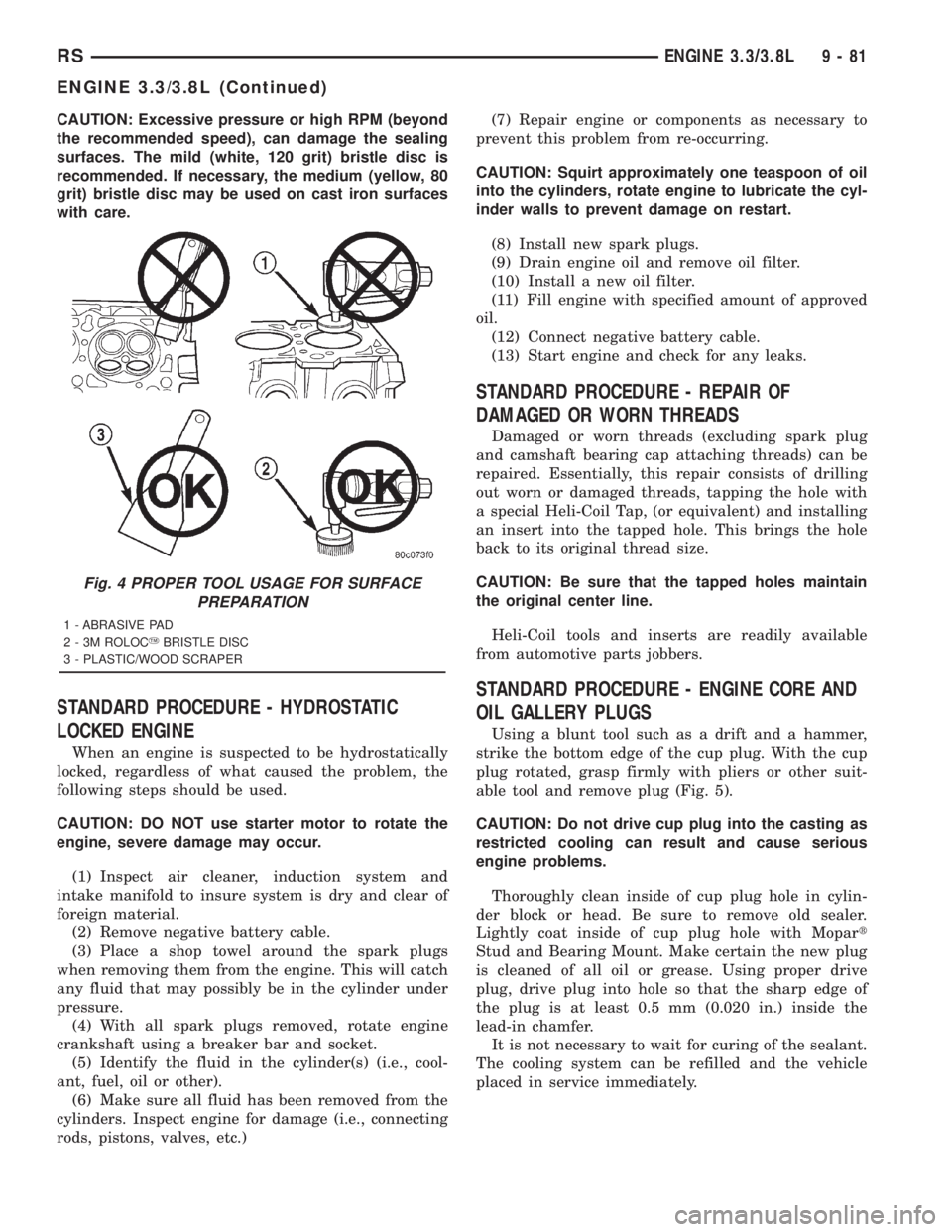
²Metal scraper
²Abrasive pad or paper to clean cylinder block
and head
²High speed power tool with an abrasive pad or a
wire brush (Fig. 4)
NOTE: Multi-Layer Steel (MLS) head gaskets require
a scratch free sealing surface.
Only use the following for cleaning gasket surfaces:
²Solvent or a commercially available gasket
remover
²Plastic or wood scraper (Fig. 4)
²Drill motor with 3M RolocyBristle Disc (white
or yellow) (Fig. 4)
9 - 80 ENGINE 3.3/3.8LRS
ENGINE 3.3/3.8L (Continued)
Page 2705 of 4284
CAUTION: Excessive pressure or high RPM (beyond
the recommended speed), can damage the sealing
surfaces. The mild (white, 120 grit) bristle disc is
recommended. If necessary, the medium (yellow, 80
grit) bristle disc may be used on cast iron surfaces
with care.
STANDARD PROCEDURE - HYDROSTATIC
LOCKED ENGINE
When an engine is suspected to be hydrostatically
locked, regardless of what caused the problem, the
following steps should be used.
CAUTION: DO NOT use starter motor to rotate the
engine, severe damage may occur.
(1) Inspect air cleaner, induction system and
intake manifold to insure system is dry and clear of
foreign material.
(2) Remove negative battery cable.
(3) Place a shop towel around the spark plugs
when removing them from the engine. This will catch
any fluid that may possibly be in the cylinder under
pressure.
(4) With all spark plugs removed, rotate engine
crankshaft using a breaker bar and socket.
(5) Identify the fluid in the cylinder(s) (i.e., cool-
ant, fuel, oil or other).
(6) Make sure all fluid has been removed from the
cylinders. Inspect engine for damage (i.e., connecting
rods, pistons, valves, etc.)(7) Repair engine or components as necessary to
prevent this problem from re-occurring.
CAUTION: Squirt approximately one teaspoon of oil
into the cylinders, rotate engine to lubricate the cyl-
inder walls to prevent damage on restart.
(8) Install new spark plugs.
(9) Drain engine oil and remove oil filter.
(10) Install a new oil filter.
(11) Fill engine with specified amount of approved
oil.
(12) Connect negative battery cable.
(13) Start engine and check for any leaks.
STANDARD PROCEDURE - REPAIR OF
DAMAGED OR WORN THREADS
Damaged or worn threads (excluding spark plug
and camshaft bearing cap attaching threads) can be
repaired. Essentially, this repair consists of drilling
out worn or damaged threads, tapping the hole with
a special Heli-Coil Tap, (or equivalent) and installing
an insert into the tapped hole. This brings the hole
back to its original thread size.
CAUTION: Be sure that the tapped holes maintain
the original center line.
Heli-Coil tools and inserts are readily available
from automotive parts jobbers.
STANDARD PROCEDURE - ENGINE CORE AND
OIL GALLERY PLUGS
Using a blunt tool such as a drift and a hammer,
strike the bottom edge of the cup plug. With the cup
plug rotated, grasp firmly with pliers or other suit-
able tool and remove plug (Fig. 5).
CAUTION: Do not drive cup plug into the casting as
restricted cooling can result and cause serious
engine problems.
Thoroughly clean inside of cup plug hole in cylin-
der block or head. Be sure to remove old sealer.
Lightly coat inside of cup plug hole with Mopart
Stud and Bearing Mount. Make certain the new plug
is cleaned of all oil or grease. Using proper drive
plug, drive plug into hole so that the sharp edge of
the plug is at least 0.5 mm (0.020 in.) inside the
lead-in chamfer.
It is not necessary to wait for curing of the sealant.
The cooling system can be refilled and the vehicle
placed in service immediately.
Fig. 4 PROPER TOOL USAGE FOR SURFACE
PREPARATION
1 - ABRASIVE PAD
2 - 3M ROLOCYBRISTLE DISC
3 - PLASTIC/WOOD SCRAPER
RSENGINE 3.3/3.8L9-81
ENGINE 3.3/3.8L (Continued)
Page 2717 of 4284
AIR CLEANER ELEMENT
REMOVAL
(1) Unsnap 2 clips.
(2) Lift cover and pull toward the engine and
remove cover tabs from air box.
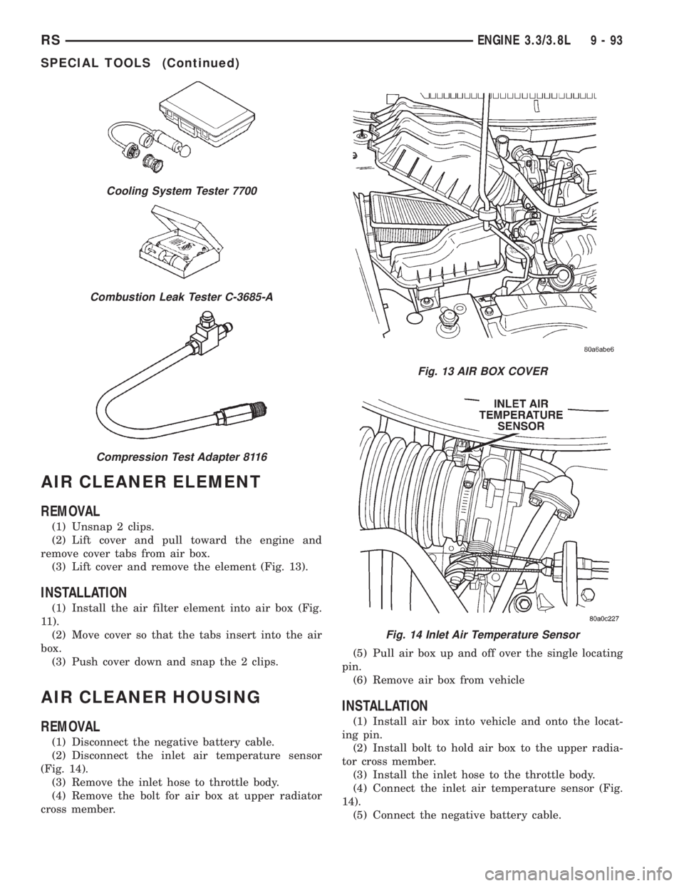
(3) Lift cover and remove the element (Fig. 13).
INSTALLATION
(1) Install the air filter element into air box (Fig.
11).
(2) Move cover so that the tabs insert into the air
box.
(3) Push cover down and snap the 2 clips.
AIR CLEANER HOUSING
REMOVAL
(1) Disconnect the negative battery cable.
(2) Disconnect the inlet air temperature sensor
(Fig. 14).
(3) Remove the inlet hose to throttle body.
(4) Remove the bolt for air box at upper radiator
cross member.(5) Pull air box up and off over the single locating
pin.
(6) Remove air box from vehicle
INSTALLATION
(1) Install air box into vehicle and onto the locat-
ing pin.
(2) Install bolt to hold air box to the upper radia-
tor cross member.
(3) Install the inlet hose to the throttle body.
(4) Connect the inlet air temperature sensor (Fig.
14).
(5) Connect the negative battery cable.
Cooling System Tester 7700
Combustion Leak Tester C-3685-A
Compression Test Adapter 8116
Fig. 13 AIR BOX COVER
Fig. 14 Inlet Air Temperature Sensor
RSENGINE 3.3/3.8L9-93
SPECIAL TOOLS (Continued)
Page 2729 of 4284
DISASSEMBLY - ROCKER ARMS AND SHAFT
CAUTION: Do not attempt to drive the bolt from the
rocker shaft. This can damage the retainer and bolt
assembly.
(1) Remove the rocker arm retainer and bolt by
performing the following procedure:
(a) Using adjustable pliers, grip the edges of the
retainer (Fig. 39).
(b) Apply an upward force with a slight rocking
motion until the retainer disengages from shaft
(Fig. 39).
(2) Remove rocker arms (Fig. 40). Identify the
component locations for reassembly in original loca-
tions.
ASSEMBLY - ROCKER ARMS AND SHAFT
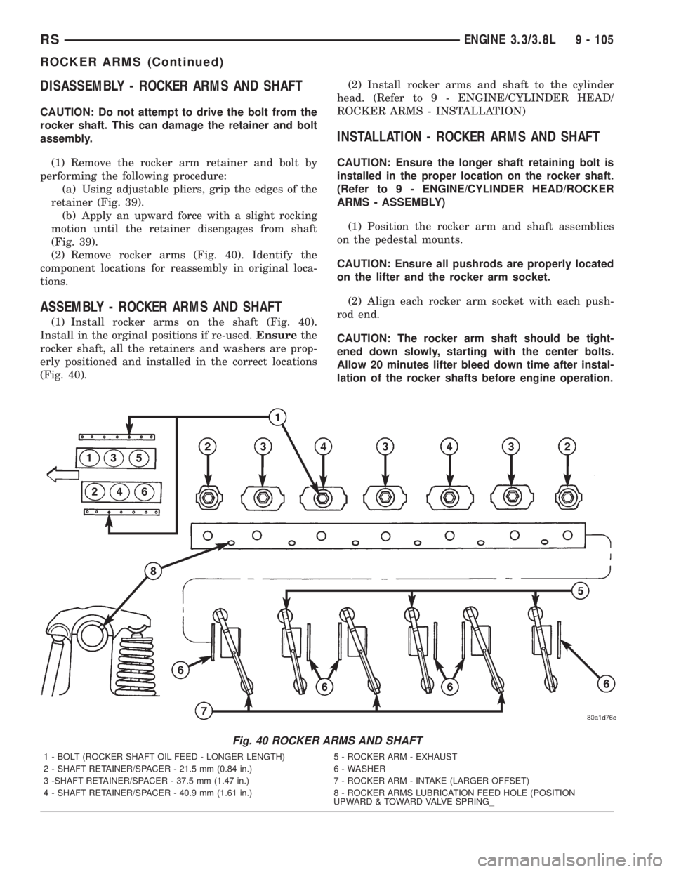
(1) Install rocker arms on the shaft (Fig. 40).
Install in the orginal positions if re-used.Ensurethe
rocker shaft, all the retainers and washers are prop-
erly positioned and installed in the correct locations
(Fig. 40).(2) Install rocker arms and shaft to the cylinder
head. (Refer to 9 - ENGINE/CYLINDER HEAD/
ROCKER ARMS - INSTALLATION)
INSTALLATION - ROCKER ARMS AND SHAFT
CAUTION: Ensure the longer shaft retaining bolt is
installed in the proper location on the rocker shaft.
(Refer to 9 - ENGINE/CYLINDER HEAD/ROCKER
ARMS - ASSEMBLY)
(1) Position the rocker arm and shaft assemblies
on the pedestal mounts.
CAUTION: Ensure all pushrods are properly located
on the lifter and the rocker arm socket.
(2) Align each rocker arm socket with each push-
rod end.
CAUTION: The rocker arm shaft should be tight-
ened down slowly, starting with the center bolts.
Allow 20 minutes lifter bleed down time after instal-
lation of the rocker shafts before engine operation.
Fig. 40 ROCKER ARMS AND SHAFT
1 - BOLT (ROCKER SHAFT OIL FEED - LONGER LENGTH) 5 - ROCKER ARM - EXHAUST
2 - SHAFT RETAINER/SPACER - 21.5 mm (0.84 in.) 6 - WASHER
3 -SHAFT RETAINER/SPACER - 37.5 mm (1.47 in.) 7 - ROCKER ARM - INTAKE (LARGER OFFSET)
4 - SHAFT RETAINER/SPACER - 40.9 mm (1.61 in.) 8 - ROCKER ARMS LUBRICATION FEED HOLE (POSITION
UPWARD & TOWARD VALVE SPRING_
RSENGINE 3.3/3.8L9 - 105
ROCKER ARMS (Continued)
Page 2743 of 4284
OIL LEVEL TOO HIGH
If oil level is above the MAX mark on dipstick, it is
possible for the connecting rods to dip into the oil
while engine is running and create foaming. Foam in
oil pan would be fed to the hydraulic lifters by the oil
pump causing them to become soft and allow valves
to seat noisily.
OIL LEVEL TOO LOW
Low oil level may allow pump to take in air which
when fed to the lifters it causes them to become soft
and allows valves to seat noisily. Any leaks on intake
side of pump, through which air can be drawn, will
create the same lifter noise. Check the lubrication
system from the intake strainer to the oil pump
cover, including the relief valve retainer cap. When
lifter noise is due to aeration, it may be intermittent
or constant, and usually more than one lifter will be
noisy. When oil level and leaks have been corrected,
the engine should be operated at fast idle to allow all
of the air inside of the lifters to be bled out.
VALVE TRAIN NOISE
To determine source of valve train noise, operate
engine at idle with cylinder head covers removed and
listen for source of the noise.
NOTE: Worn valve guides or cocked springs are
sometimes mistaken for noisy lifters. If such is the
case, noise may be dampened by applying side
thrust on the valve spring. If noise is not apprecia-
bly reduced, it can be assumed the noise is in the
tappet. Inspect the rocker arm push rod sockets
and push rod ends for wear.
Valve lifter noise ranges from light noise to a
heavy click. A light noise is usually caused by exces-
sive leak-down around the unit plunger which will
necessitate replacing the lifter, or by the plunger par-
tially sticking in the lifter body cylinder. A heavy
click is caused either by a lifter check valve not seat-
ing, or by foreign particles becoming wedged between
the plunger and the lifter body causing the plunger
to stick in the down position. This heavy click will be
accompanied by excessive clearance between the
valve stem and rocker arm as valve closes. In either
case, lifter assembly should be removed for inspec-
tion.
REMOVAL
(1) Remove the cylinder head(s). (Refer to 9 -
ENGINE/CYLINDER HEAD - REMOVAL)
(2) Remove the yoke retainer and aligning yokes
(Fig. 71).
(3) Remove the hydraulic lifters. If necessary use
Special Tool C-4129, or equivalent to remove liftersfrom bores. If lifters are to be reused, identify each
lifter to ensure installation in original location.
INSTALLATION
(1) Lubricate the lifters with engine oil.
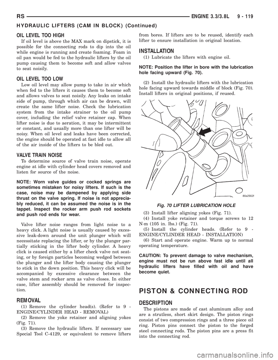
NOTE: Position the lifter in bore with the lubrication
hole facing upward (Fig. 70).
(2) Install the hydraulic lifters with the lubrication
hole facing upward towards middle of block (Fig. 70).
Install lifters in original positions, if reused.
(3) Install lifter aligning yokes (Fig. 71).
(4) Install yoke retainer and torque screws to 12
N´m (105 in. lbs.) (Fig. 71).
(5) Install the cylinder heads. (Refer to 9 -
ENGINE/CYLINDER HEAD - INSTALLATION)
(6) Start and operate engine. Warm up to normal
operating temperature.
CAUTION: To prevent damage to valve mechanism,
engine must not be run above fast idle until all
hydraulic lifters have filled with oil and have
become quiet.
PISTON & CONNECTING ROD
DESCRIPTION
The pistons are made of cast aluminum alloy and
are a strutless, short skirt design. The piston rings
consist of two compression rings and a three piece oil
ring. Piston pins connect the piston to the forged
steel connecting rods. The piston pins are a press fit
into the connecting rod.
Fig. 70 LIFTER LUBRICATION HOLE
RSENGINE 3.3/3.8L9 - 119
HYDRAULIC LIFTERS (CAM IN BLOCK) (Continued)
Page 2756 of 4284
OIL
STANDARD PROCEDURE - ENGINE OIL AND
FILTER CHANGE
Change engine oil at mileage and time intervals
described in the Maintenance Schedule. (Refer to
LUBRICATION & MAINTENANCE/MAINTE-
NANCE SCHEDULES - DESCRIPTION)
WARNING: NEW OR USED ENGINE OIL CAN BE
IRRITATING TO THE SKIN. AVOID PROLONGED OR
REPEATED SKIN CONTACT WITH ENGINE OIL.
CONTAMINANTS IN USED ENGINE OIL, CAUSED BY
INTERNAL COMBUSTION, CAN BE HAZARDOUS TO
YOUR HEALTH. THOROUGHLY WASH EXPOSED
SKIN WITH SOAP AND WATER. DO NOT WASH
SKIN WITH GASOLINE, DIESEL FUEL, THINNER, OR
SOLVENTS, HEALTH PROBLEMS CAN RESULT. DO
NOT POLLUTE, DISPOSE OF USED ENGINE OIL
PROPERLY. CONTACT YOUR DEALER OR GOVERN-
MENT AGENCY FOR LOCATION OF COLLECTION
CENTER IN YOUR AREA.
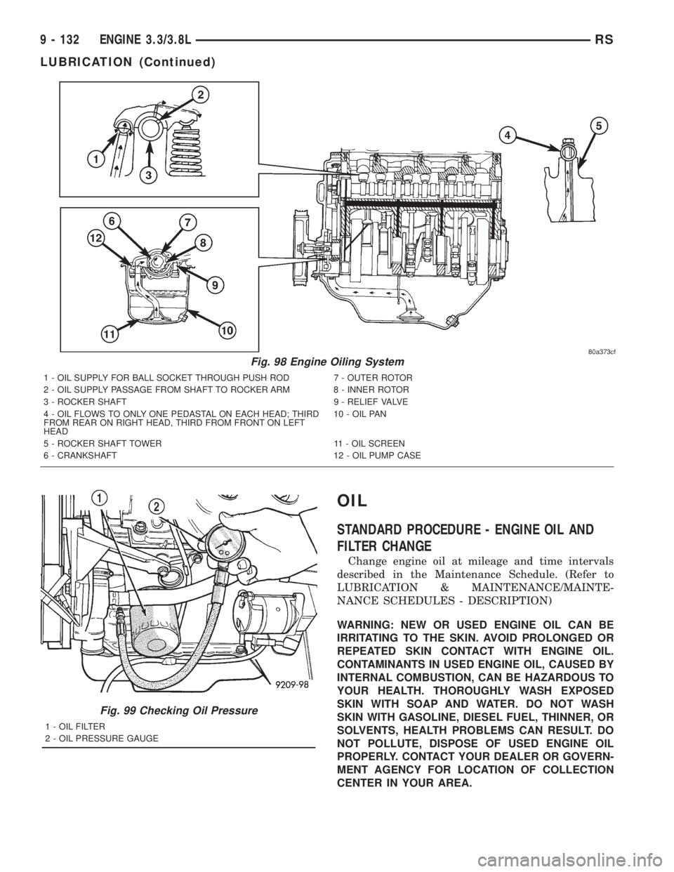
Fig. 98 Engine Oiling System
1 - OIL SUPPLY FOR BALL SOCKET THROUGH PUSH ROD 7 - OUTER ROTOR
2 - OIL SUPPLY PASSAGE FROM SHAFT TO ROCKER ARM 8 - INNER ROTOR
3 - ROCKER SHAFT 9 - RELIEF VALVE
4 - OIL FLOWS TO ONLY ONE PEDASTAL ON EACH HEAD; THIRD
FROM REAR ON RIGHT HEAD, THIRD FROM FRONT ON LEFT
HEAD10 - OIL PAN
5 - ROCKER SHAFT TOWER 11 - OIL SCREEN
6 - CRANKSHAFT 12 - OIL PUMP CASE
Fig. 99 Checking Oil Pressure
1 - OIL FILTER
2 - OIL PRESSURE GAUGE
9 - 132 ENGINE 3.3/3.8LRS
LUBRICATION (Continued)
Page 2820 of 4284
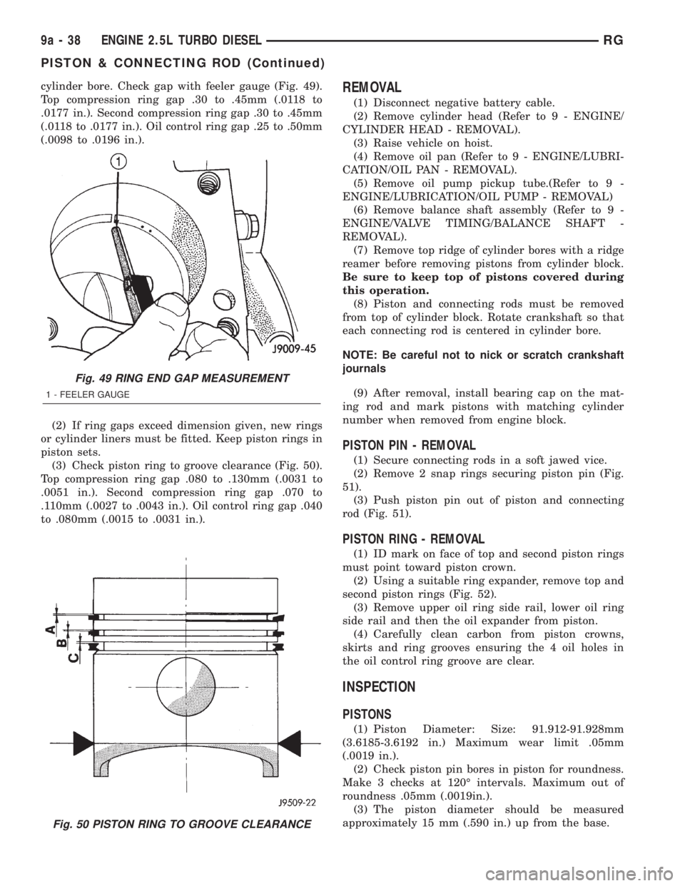
cylinder bore. Check gap with feeler gauge (Fig. 49).
Top compression ring gap .30 to .45mm (.0118 to
.0177 in.). Second compression ring gap .30 to .45mm
(.0118 to .0177 in.). Oil control ring gap .25 to .50mm
(.0098 to .0196 in.).
(2) If ring gaps exceed dimension given, new rings
or cylinder liners must be fitted. Keep piston rings in
piston sets.
(3) Check piston ring to groove clearance (Fig. 50).
Top compression ring gap .080 to .130mm (.0031 to
.0051 in.). Second compression ring gap .070 to
.110mm (.0027 to .0043 in.). Oil control ring gap .040
to .080mm (.0015 to .0031 in.).REMOVAL
(1) Disconnect negative battery cable.
(2) Remove cylinder head (Refer to 9 - ENGINE/
CYLINDER HEAD - REMOVAL).
(3) Raise vehicle on hoist.
(4) Remove oil pan (Refer to 9 - ENGINE/LUBRI-
CATION/OIL PAN - REMOVAL).
(5) Remove oil pump pickup tube.(Refer to 9 -
ENGINE/LUBRICATION/OIL PUMP - REMOVAL)
(6) Remove balance shaft assembly (Refer to 9 -
ENGINE/VALVE TIMING/BALANCE SHAFT -
REMOVAL).
(7) Remove top ridge of cylinder bores with a ridge
reamer before removing pistons from cylinder block.
Be sure to keep top of pistons covered during
this operation.
(8) Piston and connecting rods must be removed
from top of cylinder block. Rotate crankshaft so that
each connecting rod is centered in cylinder bore.
NOTE: Be careful not to nick or scratch crankshaft
journals
(9) After removal, install bearing cap on the mat-
ing rod and mark pistons with matching cylinder
number when removed from engine block.
PISTON PIN - REMOVAL
(1) Secure connecting rods in a soft jawed vice.
(2) Remove 2 snap rings securing piston pin (Fig.
51).
(3) Push piston pin out of piston and connecting
rod (Fig. 51).
PISTON RING - REMOVAL
(1) ID mark on face of top and second piston rings
must point toward piston crown.
(2) Using a suitable ring expander, remove top and
second piston rings (Fig. 52).
(3) Remove upper oil ring side rail, lower oil ring
side rail and then the oil expander from piston.
(4) Carefully clean carbon from piston crowns,
skirts and ring grooves ensuring the 4 oil holes in
the oil control ring groove are clear.
INSPECTION
PISTONS
(1) Piston Diameter: Size: 91.912-91.928mm
(3.6185-3.6192 in.) Maximum wear limit .05mm
(.0019 in.).
(2) Check piston pin bores in piston for roundness.
Make 3 checks at 120É intervals. Maximum out of
roundness .05mm (.0019in.).
(3) The piston diameter should be measured
approximately 15 mm (.590 in.) up from the base.
Fig. 49 RING END GAP MEASUREMENT
1 - FEELER GAUGE
Fig. 50 PISTON RING TO GROOVE CLEARANCE
9a - 38 ENGINE 2.5L TURBO DIESELRG
PISTON & CONNECTING ROD (Continued)
Page 2822 of 4284
PISTON PINS
(1) Measure the diameter of piston pin in the cen-
ter and both ends.
(2) Piston pin diameter is 29.992 to 29.996mm
(1.1807 to 1.1809 in.).
INSTALLATION
PISTON PIN INSTALLATION
(1) Secure connecting rod in soft jawed vice.
(2) Lubricate piston pin and piston with clean
engine oil.
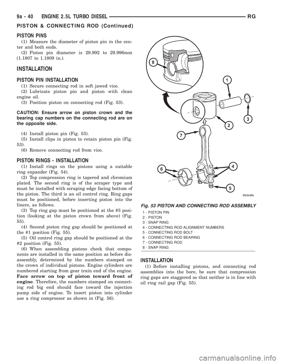
(3) Position piston on connecting rod (Fig. 53).
CAUTION: Ensure arrow on piston crown and the
bearing cap numbers on the connecting rod are on
the opposite side.
(4) Install piston pin (Fig. 53).
(5) Install clips in piston to retain piston pin (Fig.
53).
(6) Remove connecting rod from vice.
PISTON RINGS - INSTALLATION
(1) Install rings on the pistons using a suitable
ring expander (Fig. 54).
(2) Top compression ring is tapered and chromium
plated. The second ring is of the scraper type and
must be installed with scraping edge facing bottom of
the piston. The third is an oil control ring. Ring gaps
must be positioned, before inserting piston into the
liners, as follows.
(3) Top ring gap must be positioned at the #3 posi-
tion (looking at the piston crown from above) (Fig.
55).
(4) Second piston ring gap should be positioned at
the #1 position (Fig. 55).
(5) Oil control ring gap should be positioned at the
#2 position (Fig. 55).
(6) When assembling pistons check that compo-
nents are installed in the same position as before dis-
assembly, determined by the numbers stamped on
the crown of individual pistons. Engine cylinders are
numbered starting from gear train end of the engine.
Face arrow on top of piston toward front of
engine. Therefore, the numbers stamped on connect-
ing rod big end should face toward the injection
pump side of engine. To insert piston into cylinder
use a ring compressor as shown in (Fig. 56).
INSTALLATION
(1) Before installing pistons, and connecting rod
assemblies into the bore, be sure that compression
ring gaps are staggered so that neither is in line with
oil ring rail gap (Fig. 55).
Fig. 53 PISTON AND CONNECTING ROD ASSEMBLY
1 - PISTON PIN
2 - PISTON
3 - SNAP RING
4 - CONNECTING ROD ALIGNMENT NUMBERS
5 - CONNECTING ROD BOLT
6 - CONNECTING ROD BEARING
7 - CONNECTING ROD
8 - SNAP RING
9a - 40 ENGINE 2.5L TURBO DIESELRG
PISTON & CONNECTING ROD (Continued)