Page 3361 of 4284

SHIFT FORK AND SHAFT
DESCRIPTION
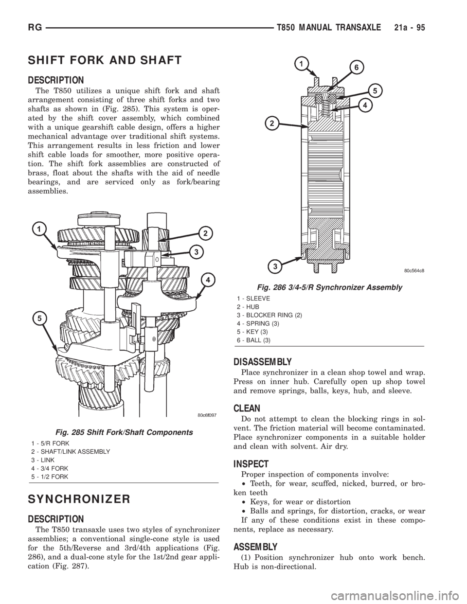
The T850 utilizes a unique shift fork and shaft
arrangement consisting of three shift forks and two
shafts as shown in (Fig. 285). This system is oper-
ated by the shift cover assembly, which combined
with a unique gearshift cable design, offers a higher
mechanical advantage over traditional shift systems.
This arrangement results in less friction and lower
shift cable loads for smoother, more positive opera-
tion. The shift fork assemblies are constructed of
brass, float about the shafts with the aid of needle
bearings, and are serviced only as fork/bearing
assemblies.
SYNCHRONIZER
DESCRIPTION
The T850 transaxle uses two styles of synchronizer
assemblies; a conventional single-cone style is used
for the 5th/Reverse and 3rd/4th applications (Fig.
286), and a dual-cone style for the 1st/2nd gear appli-
cation (Fig. 287).
DISASSEMBLY
Place synchronizer in a clean shop towel and wrap.
Press on inner hub. Carefully open up shop towel
and remove springs, balls, keys, hub, and sleeve.
CLEAN
Do not attempt to clean the blocking rings in sol-
vent. The friction material will become contaminated.
Place synchronizer components in a suitable holder
and clean with solvent. Air dry.
INSPECT
Proper inspection of components involve:
²Teeth, for wear, scuffed, nicked, burred, or bro-
ken teeth
²Keys, for wear or distortion
²Balls and springs, for distortion, cracks, or wear
If any of these conditions exist in these compo-
nents, replace as necessary.
ASSEMBLY
(1) Position synchronizer hub onto work bench.
Hub is non-directional.
Fig. 285 Shift Fork/Shaft Components
1 - 5/R FORK
2 - SHAFT/LINK ASSEMBLY
3 - LINK
4 - 3/4 FORK
5 - 1/2 FORK
Fig. 286 3/4-5/R Synchronizer Assembly
1 - SLEEVE
2 - HUB
3 - BLOCKER RING (2)
4 - SPRING (3)
5 - KEY (3)
6 - BALL (3)
RGT850 MANUAL TRANSAXLE21a-95
Page 3366 of 4284

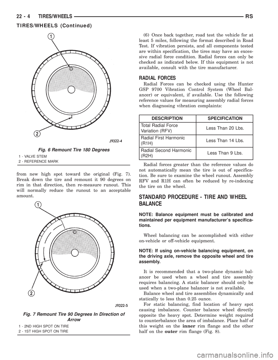
from new high spot toward the original (Fig. 7).
Break down the tire and remount it 90 degrees on
rim in that direction, then re-measure runout. This
will normally reduce the runout to an acceptable
amount.(6) Once back together, road test the vehicle for at
least 5 miles, following the format described in Road
Test. If vibration persists, and all components tested
are within specification, the tires may have an exces-
sive radial force condition. Radial forces can only be
checked as indicated below. If this equipment is not
available, consult with the tire manufacturer.
RADIAL FORCES
Radial Forces can be checked using the Hunter
GSP 9700 Vibration Control System (Wheel Bal-
ancer) or equivalent, if available. Use the following
reference values for measuring assembly radial forces
when diagnosing vibration complaints:
DESCRIPTION SPECIFICATION
Total Radial Force
Variation (RFV)Less Than 20 Lbs.
Radial First Harmonic
(R1H)Less Than 14 Lbs.
Radial Second Harmonic
(R2H)Less Than 9 Lbs.
Radial forces greater than the reference values do
not automatically mean the tire is out of specifica-
tion. Be sure to examine the wheel runout. Assembly
RFV and R1H can often be reduced by re-indexing
the tire on the wheel.
STANDARD PROCEDURE - TIRE AND WHEEL
BALANCE
NOTE: Balance equipment must be calibrated and
maintained per equipment manufacturer's specifica-
tions.
Wheel balancing can be accomplished with either
on-vehicle or off-vehicle equipment.
NOTE: If using on-vehicle balancing equipment, on
the driving axle, remove the opposite wheel and tire
assembly.
It is recommended that a two-plane dynamic bal-
ancer be used when a wheel and tire assembly
requires balancing. A static balancer should only be
used when a two-plane balancer is not available.
Balance wheel and tire assemblies dynamically and
statically to less than 0.25 ounce.
For static balancing, find location of heavy spot
causing imbalance. Counter balance wheel directly
opposite the heavy spot. Determine weight required
to counterbalance the area of imbalance. Place half of
this weight on theinnerrim flange and the other
half on theouterrim flange (Fig. 8).
Fig. 6 Remount Tire 180 Degrees
1 - VALVE STEM
2 - REFERENCE MARK
Fig. 7 Remount Tire 90 Degrees In Direction of
Arrow
1 - 2ND HIGH SPOT ON TIRE
2 - 1ST HIGH SPOT ON TIRE
22 - 4 TIRES/WHEELSRS
TIRES/WHEELS (Continued)
Page 3402 of 4284
SHOCK TOWER AREA - LEFT AND RIGHT SIDES
OUTER SHOCK TOWER AREA - LEFT AND RIGHT SIDES
23 - 22 BODYRS
BODY (Continued)
Page 3408 of 4284
UPPER LIFTGATE PANEL SILL - LEFT AND RIGHT SIDES
FRONT WHEELHOUSE & SHOCK TOWER - LEFT AND RIGHT SIDES
23 - 28 BODYRS
BODY (Continued)
Page 3429 of 4284
STRUT TOWER AND REINFORCEMENTS - RIGHT
RSBODY23-49
BODY (Continued)
Page 3431 of 4284
STRUT TOWER AND REINFORCEMENTS - LEFT
RSBODY23-51
BODY (Continued)
Page 3449 of 4284
ENGINE MOUNTING PLATE AND TOW BRACKET
RSBODY23-69
BODY (Continued)
Page 3456 of 4284
REAR SUPPORT AND TIRE STOWAGE CROSS MEMBERS - LONG WHEEL BASE ONLY
23 - 76 BODYRS
BODY (Continued)