2001 CHRYSLER VOYAGER tow
[x] Cancel search: towPage 2564 of 4284
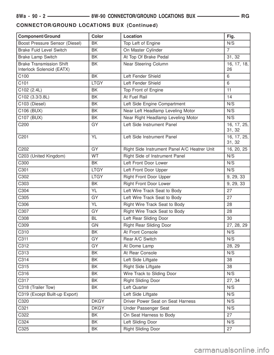
Component/Ground Color Location Fig.
Boost Pressure Sensor (Diesel) BK Top Left of Engine N/S
Brake Fuid Level Switch BK On Master Cylinder 7
Brake Lamp Switch BK At Top Of Brake Pedal 31, 32
Brake Transmission Shift
Interlock Solenoid (EATX)BK Near Steering Column 16, 17, 18,
26
C100 BK Left Fender Shield 6
C101 LTGY Left Fender Shield 6
C102 (2.4L) BK Top Front of Engine 11
C102 (3.3/3.8L) BK At Fuel Rail 14
C103 (Diesel) BK Left Side Engine Compartment N/S
C106 (BUX) BK Near Left Headlamp Leveling Motor N/S
C107 (BUX) BK Near Right Headlamp Leveling Motor N/S
C200 GY Left Side Instrument Panel 16, 17, 25,
31, 32
C201 YL Left Side Instrument Panel 16, 17, 25,
31, 32
C202 GY Right Side Instrument Panel A/C Heatrer Unit 16, 20, 25
C203 (United Kingdom) WT Right Side of Instrument Panel N/S
C300 BK Left Front Door Lower N/S
C301 LTGY Left Front Door Upper N/S
C302 LTGY Right Front Door Upper 9, 29, 33
C303 BK Right Front Door Lower 9, 29, 33
C304 YL Left Wire Track Seat to Body 27
C305 GY Left Wire Track Seat to Body 27
C306 YL Right Wire Track Seat to Body 28
C307 GY Right Wire Track Seat to Body 28
C308 BL Left Rear Sliding Door 30
C309 GN Right Rear Sliding Door 27, 28, 29
C310 BK At Front Console N/S
C311 GY Rear A/C Switch N/S
C312 GY At Dome Lamp 28, 29
C313 BK At Rear Console N/S
C314 BK Left Side Liftgate 38
C315 BK Right Side Liftgate 38
C316 BK Wire Track to Sliding Door N/S
C317 BK Right Sliding Door 27, 34
C318 (Trailer Tow) BK Left Quarter N/S
C319 (Except Built-up Export) Left Side Liftgate N/S
C320 DKGY Driver Power Seat on Seat Harness N/S
C321 DKGY Under Passenger Seat N/S
C322 BK On Seat Harness to Body 27
C324 BK Left Sliding Door N/S
C325 BK Right Sliding Door 27
8Wa - 90 - 2 8W-90 CONNECTOR/GROUND LOCATIONS BUXRG
CONNECTOR/GROUND LOCATIONS BUX (Continued)
Page 2573 of 4284
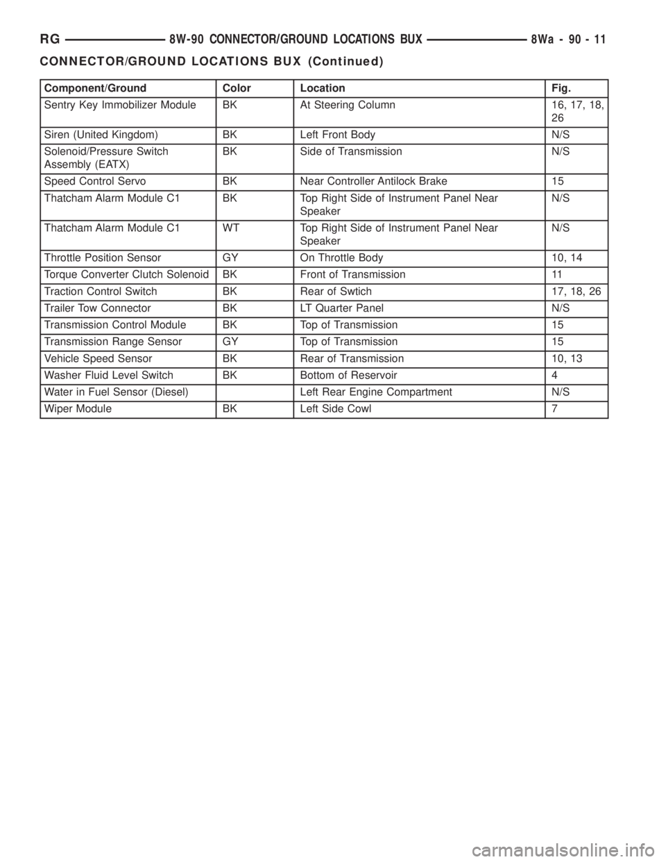
Component/Ground Color Location Fig.
Sentry Key Immobilizer Module BK At Steering Column 16, 17, 18,
26
Siren (United Kingdom) BK Left Front Body N/S
Solenoid/Pressure Switch
Assembly (EATX)BK Side of Transmission N/S
Speed Control Servo BK Near Controller Antilock Brake 15
Thatcham Alarm Module C1 BK Top Right Side of Instrument Panel Near
SpeakerN/S
Thatcham Alarm Module C1 WT Top Right Side of Instrument Panel Near
SpeakerN/S
Throttle Position Sensor GY On Throttle Body 10, 14
Torque Converter Clutch Solenoid BK Front of Transmission 11
Traction Control Switch BK Rear of Swtich 17, 18, 26
Trailer Tow Connector BK LT Quarter Panel N/S
Transmission Control Module BK Top of Transmission 15
Transmission Range Sensor GY Top of Transmission 15
Vehicle Speed Sensor BK Rear of Transmission 10, 13
Washer Fluid Level Switch BK Bottom of Reservoir 4
Water in Fuel Sensor (Diesel) Left Rear Engine Compartment N/S
Wiper Module BK Left Side Cowl 7
RG8W-90 CONNECTOR/GROUND LOCATIONS BUX8Wa-90-11
CONNECTOR/GROUND LOCATIONS BUX (Continued)
Page 2634 of 4284
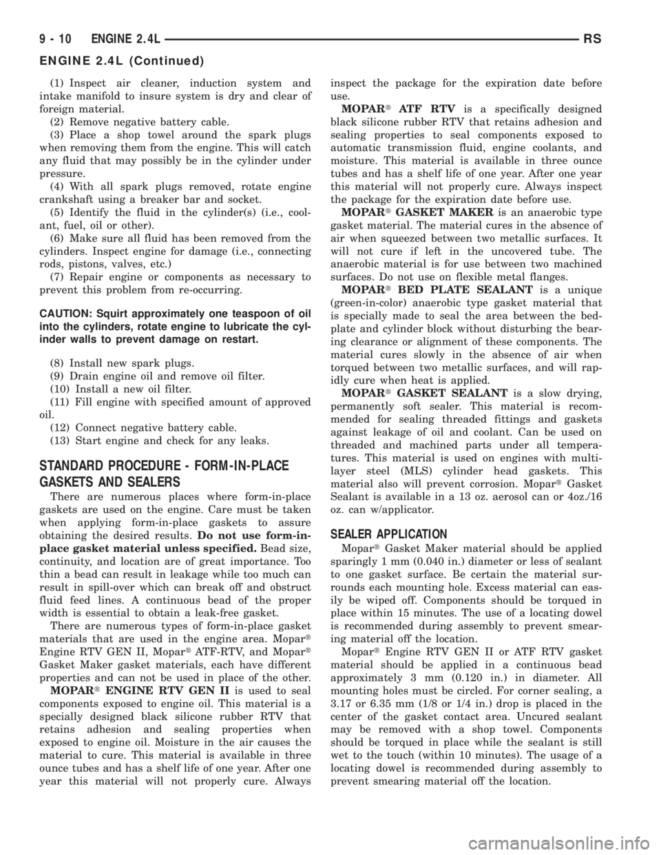
(1) Inspect air cleaner, induction system and
intake manifold to insure system is dry and clear of
foreign material.
(2) Remove negative battery cable.
(3) Place a shop towel around the spark plugs
when removing them from the engine. This will catch
any fluid that may possibly be in the cylinder under
pressure.
(4) With all spark plugs removed, rotate engine
crankshaft using a breaker bar and socket.
(5) Identify the fluid in the cylinder(s) (i.e., cool-
ant, fuel, oil or other).
(6) Make sure all fluid has been removed from the
cylinders. Inspect engine for damage (i.e., connecting
rods, pistons, valves, etc.)
(7) Repair engine or components as necessary to
prevent this problem from re-occurring.
CAUTION: Squirt approximately one teaspoon of oil
into the cylinders, rotate engine to lubricate the cyl-
inder walls to prevent damage on restart.
(8) Install new spark plugs.
(9) Drain engine oil and remove oil filter.
(10) Install a new oil filter.
(11) Fill engine with specified amount of approved
oil.
(12) Connect negative battery cable.
(13) Start engine and check for any leaks.
STANDARD PROCEDURE - FORM-IN-PLACE
GASKETS AND SEALERS
There are numerous places where form-in-place
gaskets are used on the engine. Care must be taken
when applying form-in-place gaskets to assure
obtaining the desired results.Do not use form-in-
place gasket material unless specified.Bead size,
continuity, and location are of great importance. Too
thin a bead can result in leakage while too much can
result in spill-over which can break off and obstruct
fluid feed lines. A continuous bead of the proper
width is essential to obtain a leak-free gasket.
There are numerous types of form-in-place gasket
materials that are used in the engine area. Mopart
Engine RTV GEN II, MopartATF-RTV, and Mopart
Gasket Maker gasket materials, each have different
properties and can not be used in place of the other.
MOPARtENGINE RTV GEN IIis used to seal
components exposed to engine oil. This material is a
specially designed black silicone rubber RTV that
retains adhesion and sealing properties when
exposed to engine oil. Moisture in the air causes the
material to cure. This material is available in three
ounce tubes and has a shelf life of one year. After one
year this material will not properly cure. Alwaysinspect the package for the expiration date before
use.
MOPARtATF RTVis a specifically designed
black silicone rubber RTV that retains adhesion and
sealing properties to seal components exposed to
automatic transmission fluid, engine coolants, and
moisture. This material is available in three ounce
tubes and has a shelf life of one year. After one year
this material will not properly cure. Always inspect
the package for the expiration date before use.
MOPARtGASKET MAKERis an anaerobic type
gasket material. The material cures in the absence of
air when squeezed between two metallic surfaces. It
will not cure if left in the uncovered tube. The
anaerobic material is for use between two machined
surfaces. Do not use on flexible metal flanges.
MOPARtBED PLATE SEALANTis a unique
(green-in-color) anaerobic type gasket material that
is specially made to seal the area between the bed-
plate and cylinder block without disturbing the bear-
ing clearance or alignment of these components. The
material cures slowly in the absence of air when
torqued between two metallic surfaces, and will rap-
idly cure when heat is applied.
MOPARtGASKET SEALANTis a slow drying,
permanently soft sealer. This material is recom-
mended for sealing threaded fittings and gaskets
against leakage of oil and coolant. Can be used on
threaded and machined parts under all tempera-
tures. This material is used on engines with multi-
layer steel (MLS) cylinder head gaskets. This
material also will prevent corrosion. MopartGasket
Sealant is available in a 13 oz. aerosol can or 4oz./16
oz. can w/applicator.
SEALER APPLICATION
MopartGasket Maker material should be applied
sparingly 1 mm (0.040 in.) diameter or less of sealant
to one gasket surface. Be certain the material sur-
rounds each mounting hole. Excess material can eas-
ily be wiped off. Components should be torqued in
place within 15 minutes. The use of a locating dowel
is recommended during assembly to prevent smear-
ing material off the location.
MopartEngine RTV GEN II or ATF RTV gasket
material should be applied in a continuous bead
approximately 3 mm (0.120 in.) in diameter. All
mounting holes must be circled. For corner sealing, a
3.17 or 6.35 mm (1/8 or 1/4 in.) drop is placed in the
center of the gasket contact area. Uncured sealant
may be removed with a shop towel. Components
should be torqued in place while the sealant is still
wet to the touch (within 10 minutes). The usage of a
locating dowel is recommended during assembly to
prevent smearing material off the location.
9 - 10 ENGINE 2.4LRS
ENGINE 2.4L (Continued)
Page 2646 of 4284
AIR CLEANER ELEMENT
REMOVAL
(1) Unsnap 2 clips.
(2) Lift cover and pull toward the engine and
remove cover tabs from air box.
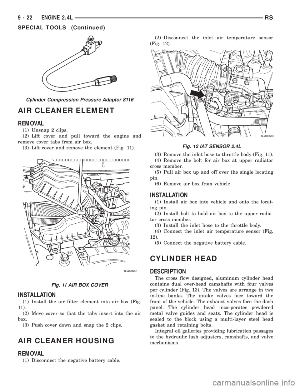
(3) Lift cover and remove the element (Fig. 11).
INSTALLATION
(1) Install the air filter element into air box (Fig.
11).
(2) Move cover so that the tabs insert into the air
box.
(3) Push cover down and snap the 2 clips.
AIR CLEANER HOUSING
REMOVAL
(1) Disconnect the negative battery cable.(2) Disconnect the inlet air temperature sensor
(Fig. 12).
(3) Remove the inlet hose to throttle body (Fig. 11).
(4) Remove the bolt for air box at upper radiator
cross member.
(5) Pull air box up and off over the single locating
pin.
(6) Remove air box from vehicle
INSTALLATION
(1) Install air box into vehicle and onto the locat-
ing pin.
(2) Install bolt to hold air box to the upper radia-
tor cross member.
(3) Install the inlet hose to the throttle body.
(4) Connect the inlet air temperature sensor (Fig.
12).
(5) Connect the negative battery cable.
CYLINDER HEAD
DESCRIPTION
The cross flow designed, aluminum cylinder head
contains dual over-head camshafts with four valves
per cylinder (Fig. 13). The valves are arrange in two
in-line banks. The intake valves face toward the
front of the vehicle. The exhaust valves face the dash
panel. The cylinder head incorporates powdered
metal valve guides and seats. The cylinder head is
sealed to the block using a multi-layer steel head
gasket and retaining bolts.
Integral oil galleries providing lubrication passages
to the hydraulic lash adjusters, camshafts, and valve
mechanisms.
Cylinder Compression Pressure Adaptor 8116
Fig. 11 AIR BOX COVER
Fig. 12 IAT SENSOR 2.4L
9 - 22 ENGINE 2.4LRS
SPECIAL TOOLS (Continued)
Page 2664 of 4284
(5) Install lower main bearings into main bearing
cap/bedplate. Make certain the bearing tabs are
seated into the bedplate slots.
(6) Position the main bearing/bedplate onto the
engine block.
(7) Before installing bolts, lubricate the threads
with clean engine oil, wipe off any excess oil.
(8) Install main bearing bedplate to engine block
bolts 11, 17 and 20 finger tight. Tighten these bolts
down together until the bedplate contacts the cylin-
der block.
(9) To ensure correct thrust bearing alignment,
perform the following steps:
²Step 1: Rotate crankshaft until number 4 piston
is at TDC.
²Step 2: Move crankshaft rearward to limits of
travel.
²Step 3: Then, move crankshaft forward to limits
of travel.
²Step 4: Wedge an appropriate tool between the
rear of the cylinder block(NOT BED PLATE)and
the rear crankshaft counterweight. This will hold the
crankshaft in it's furthest forward position.
²Step 5: Install and tighten bolts (1±10) in
sequence shown in (Fig. 57) to 41 N´m (30 ft. lbs.).
²Step 6: Remove wedge tool used to hold crank-
shaft.
(10) Tighten bolts (1±10) again to 41 N´m (30 ft.
lbs.)PLUS1/4 turn in sequence shown in (Fig. 57).
(11) Install main bearing bedplate to engine block
bolts (11±20), and torque each bolt to 28 N´m (20 ft.
lbs.) in sequence shown in (Fig. 57).
(12) After the main bearing bedplate is installed,
check the crankshaft turning torque. The turning
torque should not exceed 5.6 N´m (50 in. lbs.).
CRANKSHAFT OIL SEAL -
FRONT
REMOVAL
(1) Remove the crankshaft vibration damper.
(Refer to 9 - ENGINE/ENGINE BLOCK/VIBRATION
DAMPER - REMOVAL)
(2) Remove timing belt. (Refer to 9 - ENGINE/
VALVE TIMING/TIMING BELT/CHAIN AND
SPROCKETS - REMOVAL)
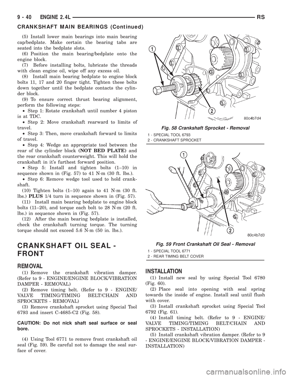
(3) Remove crankshaft sprocket using Special Tool
6793 and insert C-4685-C2 (Fig. 58).
CAUTION: Do not nick shaft seal surface or seal
bore.
(4) Using Tool 6771 to remove front crankshaft oil
seal (Fig. 59). Be careful not to damage the seal sur-
face of cover.INSTALLATION
(1) Install new seal by using Special Tool 6780
(Fig. 60).
(2) Place seal into opening with seal spring
towards the inside of engine. Install seal until flush
with cover.
(3) Install crankshaft sprocket using Special Tool
6792 (Fig. 61).
(4) Install timing belt. (Refer to 9 - ENGINE/
VALVE TIMING/TIMING BELT/CHAIN AND
SPROCKETS - INSTALLATION)
(5) Install crankshaft vibration damper. (Refer to 9
- ENGINE/ENGINE BLOCK/VIBRATION DAMPER -
INSTALLATION)
Fig. 58 Crankshaft Sprocket - Removal
1 - SPECIAL TOOL 6793
2 - CRANKSHAFT SPROCKET
Fig. 59 Front Crankshaft Oil Seal - Removal
1 - SPECIAL TOOL 6771
2 - REAR TIMING BELT COVER
9 - 40 ENGINE 2.4LRS
CRANKSHAFT MAIN BEARINGS (Continued)
Page 2666 of 4284
NOTE: When installing seal, no lube on seal is
needed.
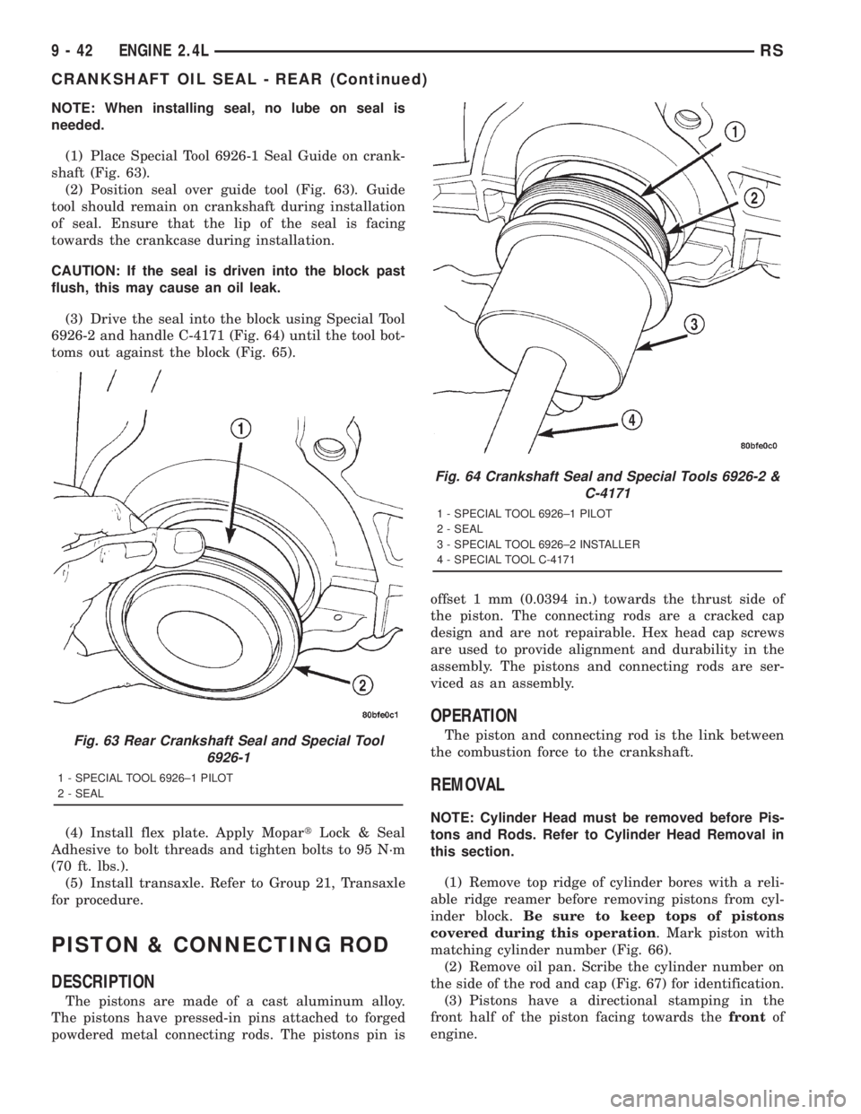
(1) Place Special Tool 6926-1 Seal Guide on crank-
shaft (Fig. 63).
(2) Position seal over guide tool (Fig. 63). Guide
tool should remain on crankshaft during installation
of seal. Ensure that the lip of the seal is facing
towards the crankcase during installation.
CAUTION: If the seal is driven into the block past
flush, this may cause an oil leak.
(3) Drive the seal into the block using Special Tool
6926-2 and handle C-4171 (Fig. 64) until the tool bot-
toms out against the block (Fig. 65).
(4) Install flex plate. Apply MopartLock & Seal
Adhesive to bolt threads and tighten bolts to 95 N´m
(70 ft. lbs.).
(5) Install transaxle. Refer to Group 21, Transaxle
for procedure.
PISTON & CONNECTING ROD
DESCRIPTION
The pistons are made of a cast aluminum alloy.
The pistons have pressed-in pins attached to forged
powdered metal connecting rods. The pistons pin isoffset 1 mm (0.0394 in.) towards the thrust side of
the piston. The connecting rods are a cracked cap
design and are not repairable. Hex head cap screws
are used to provide alignment and durability in the
assembly. The pistons and connecting rods are ser-
viced as an assembly.
OPERATION
The piston and connecting rod is the link between
the combustion force to the crankshaft.
REMOVAL
NOTE: Cylinder Head must be removed before Pis-
tons and Rods. Refer to Cylinder Head Removal in
this section.
(1) Remove top ridge of cylinder bores with a reli-
able ridge reamer before removing pistons from cyl-
inder block.Be sure to keep tops of pistons
covered during this operation. Mark piston with
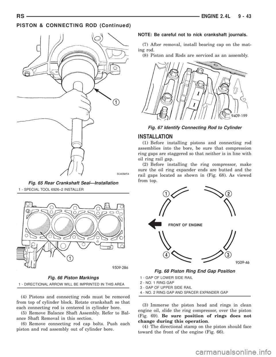
matching cylinder number (Fig. 66).
(2) Remove oil pan. Scribe the cylinder number on
the side of the rod and cap (Fig. 67) for identification.
(3) Pistons have a directional stamping in the
front half of the piston facing towards thefrontof
engine.
Fig. 63 Rear Crankshaft Seal and Special Tool
6926-1
1 - SPECIAL TOOL 6926±1 PILOT
2 - SEAL
Fig. 64 Crankshaft Seal and Special Tools 6926-2 &
C-4171
1 - SPECIAL TOOL 6926±1 PILOT
2 - SEAL
3 - SPECIAL TOOL 6926±2 INSTALLER
4 - SPECIAL TOOL C-4171
9 - 42 ENGINE 2.4LRS
CRANKSHAFT OIL SEAL - REAR (Continued)
Page 2667 of 4284
(4) Pistons and connecting rods must be removed
from top of cylinder block. Rotate crankshaft so that
each connecting rod is centered in cylinder bore.
(5) Remove Balance Shaft Assembly. Refer to Bal-
ance Shaft Removal in this section.
(6) Remove connecting rod cap bolts. Push each
piston and rod assembly out of cylinder bore.NOTE: Be careful not to nick crankshaft journals.
(7) After removal, install bearing cap on the mat-
ing rod.
(8) Piston and Rods are serviced as an assembly.
INSTALLATION
(1) Before installing pistons and connecting rod
assemblies into the bore, be sure that compression
ring gaps are staggered so that neither is in line with
oil ring rail gap.
(2) Before installing the ring compressor, make
sure the oil ring expander ends are butted and the
rail gaps located as shown in (Fig. 68). As viewed
from top.
(3) Immerse the piston head and rings in clean
engine oil, slide the ring compressor, over the piston
(Fig. 69).Be sure position of rings does not
change during this operation.
(4) The directional stamp on the piston should face
toward the front of the engine (Fig. 66).
Fig. 65 Rear Crankshaft SealÐInstallation
1 - SPECIAL TOOL 6926±2 INSTALLER
Fig. 66 Piston Markings
1 - DIRECTIONAL ARROW WILL BE IMPRINTED IN THIS AREA
Fig. 67 Identify Connecting Rod to Cylinder
Fig. 68 Piston Ring End Gap Position
1 - GAP OF LOWER SIDE RAIL
2 - NO. 1 RING GAP
3 - GAP OF UPPER SIDE RAIL
4 - NO. 2 RING GAP AND SPACER EXPANDER GAP
RSENGINE 2.4L9-43
PISTON & CONNECTING ROD (Continued)
Page 2674 of 4284
RIGHT MOUNT
REMOVAL
(1) Remove air cleaner housing lid and clean air
hose from throttle body.
(2) Remove air cleaner element and housing.
(3) Disconnect make-up air hose from cylinder
head cover.
(4) Remove the load on the right engine mount by
carefully supporting the engine assembly with a floor
jack.
(5) Disconnect electrical harness support clips from
engine mount bracket.
(6) Remove the vertical bolts attaching the engine
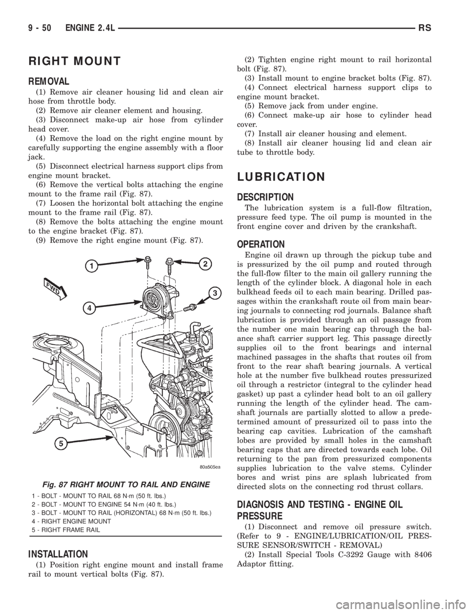
mount to the frame rail (Fig. 87).
(7) Loosen the horizontal bolt attaching the engine
mount to the frame rail (Fig. 87).
(8) Remove the bolts attaching the engine mount
to the engine bracket (Fig. 87).
(9) Remove the right engine mount (Fig. 87).
INSTALLATION
(1) Position right engine mount and install frame
rail to mount vertical bolts (Fig. 87).(2) Tighten engine right mount to rail horizontal
bolt (Fig. 87).
(3) Install mount to engine bracket bolts (Fig. 87).
(4) Connect electrical harness support clips to
engine mount bracket.
(5) Remove jack from under engine.
(6) Connect make-up air hose to cylinder head
cover.
(7) Install air cleaner housing and element.
(8) Install air cleaner housing lid and clean air
tube to throttle body.
LUBRICATION
DESCRIPTION
The lubrication system is a full-flow filtration,
pressure feed type. The oil pump is mounted in the
front engine cover and driven by the crankshaft.
OPERATION
Engine oil drawn up through the pickup tube and
is pressurized by the oil pump and routed through
the full-flow filter to the main oil gallery running the
length of the cylinder block. A diagonal hole in each
bulkhead feeds oil to each main bearing. Drilled pas-
sages within the crankshaft route oil from main bear-
ing journals to connecting rod journals. Balance shaft
lubrication is provided through an oil passage from
the number one main bearing cap through the bal-
ance shaft carrier support leg. This passage directly
supplies oil to the front bearings and internal
machined passages in the shafts that routes oil from
front to the rear shaft bearing journals. A vertical
hole at the number five bulkhead routes pressurized
oil through a restrictor (integral to the cylinder head
gasket) up past a cylinder head bolt to an oil gallery
running the length of the cylinder head. The cam-
shaft journals are partially slotted to allow a prede-
termined amount of pressurized oil to pass into the
bearing cap cavities. Lubrication of the camshaft
lobes are provided by small holes in the camshaft
bearing caps that are directed towards each lobe. Oil
returning to the pan from pressurized components
supplies lubrication to the valve stems. Cylinder
bores and wrist pins are splash lubricated from
directed slots on the connecting rod thrust collars.
DIAGNOSIS AND TESTING - ENGINE OIL
PRESSURE
(1) Disconnect and remove oil pressure switch.
(Refer to 9 - ENGINE/LUBRICATION/OIL PRES-
SURE SENSOR/SWITCH - REMOVAL)
(2) Install Special Tools C-3292 Gauge with 8406
Adaptor fitting.
Fig. 87 RIGHT MOUNT TO RAIL AND ENGINE
1 - BOLT - MOUNT TO RAIL 68 N´m (50 ft. lbs.)
2 - BOLT - MOUNT TO ENGINE 54 N´m (40 ft. lbs.)
3 - BOLT - MOUNT TO RAIL (HORIZONTAL) 68 N´m (50 ft. lbs.)
4 - RIGHT ENGINE MOUNT
5 - RIGHT FRAME RAIL
9 - 50 ENGINE 2.4LRS