2001 CHRYSLER VOYAGER height
[x] Cancel search: heightPage 2800 of 4284
CYLINDER HEAD
STANDARD PROCEDURE - VALVE SERVICE
This procedure is done with the engine cylinder
head removed from the block.
DISASSEMBLY
(1) Remove the engine cylinder head from the cyl-
inder block. Refer to cylinder head removal and
installation in this section.
(2) Use Valve Spring Compressor Tool and com-
press each valve spring.
(3) Remove the valve locks, retainers, and springs.
(4) Use an Arkansas smooth stone or a jewelers
file to remove any burrs on the top of the valve stem,
especially around the groove for the locks.
(5) Remove the valves, and place them in a rack in
the same order as removed.
VALVE CLEANING
(1) Clean all carbon deposits from the combustion
chambers, valve ports, valve stems, valve stem
guides and head.
(2) Clean all grime and gasket material from the
engine cylinder head machined gasket surface.
INSPECTION
(1) Inspect for cracks in the combustion chambers
and valve ports.
(2) Inspect for cracks on the exhaust seat.
(3) Inspect for cracks in the gasket surface at each
coolant passage.
(4) Inspect valves for burned, cracked or warped
heads.
(5) Inspect for scuffed or bent valve stems.
(6) Replace valves displaying any damage.
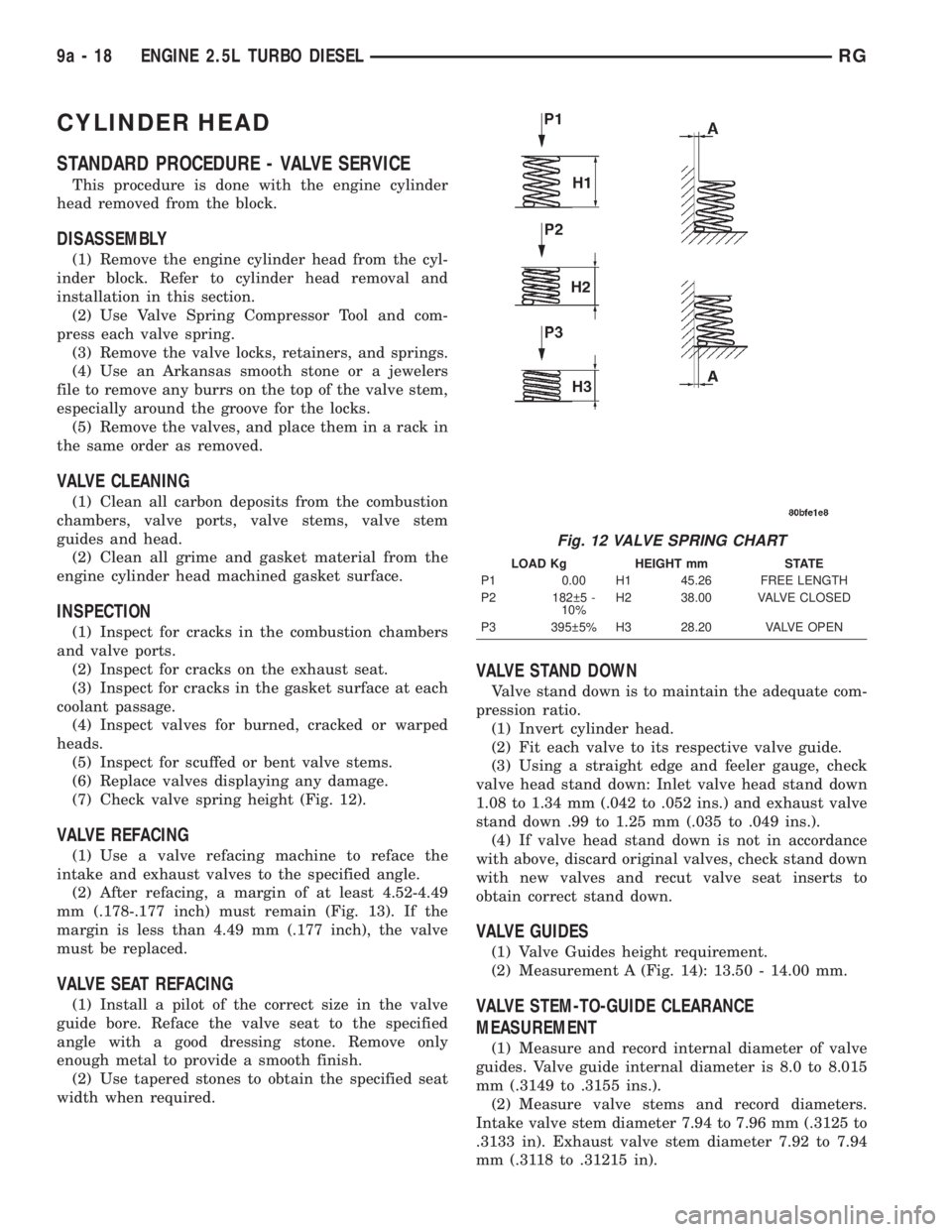
(7) Check valve spring height (Fig. 12).
VALVE REFACING
(1) Use a valve refacing machine to reface the
intake and exhaust valves to the specified angle.
(2) After refacing, a margin of at least 4.52-4.49
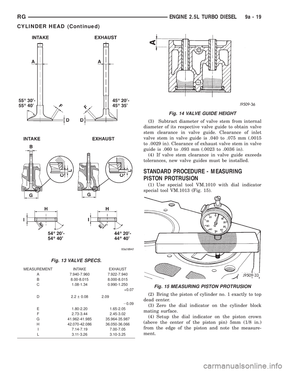
mm (.178-.177 inch) must remain (Fig. 13). If the
margin is less than 4.49 mm (.177 inch), the valve
must be replaced.
VALVE SEAT REFACING
(1) Install a pilot of the correct size in the valve
guide bore. Reface the valve seat to the specified
angle with a good dressing stone. Remove only
enough metal to provide a smooth finish.
(2) Use tapered stones to obtain the specified seat
width when required.
VALVE STAND DOWN
Valve stand down is to maintain the adequate com-
pression ratio.
(1) Invert cylinder head.
(2) Fit each valve to its respective valve guide.
(3) Using a straight edge and feeler gauge, check
valve head stand down: Inlet valve head stand down
1.08 to 1.34 mm (.042 to .052 ins.) and exhaust valve
stand down .99 to 1.25 mm (.035 to .049 ins.).
(4) If valve head stand down is not in accordance
with above, discard original valves, check stand down
with new valves and recut valve seat inserts to
obtain correct stand down.
VALVE GUIDES
(1) Valve Guides height requirement.
(2) Measurement A (Fig. 14): 13.50 - 14.00 mm.
VALVE STEM-TO-GUIDE CLEARANCE
MEASUREMENT
(1) Measure and record internal diameter of valve
guides. Valve guide internal diameter is 8.0 to 8.015
mm (.3149 to .3155 ins.).
(2) Measure valve stems and record diameters.
Intake valve stem diameter 7.94 to 7.96 mm (.3125 to
.3133 in). Exhaust valve stem diameter 7.92 to 7.94
mm (.3118 to .31215 in).
Fig. 12 VALVE SPRING CHART
LOAD Kg HEIGHT mm STATE
P1 0.00 H1 45.26 FREE LENGTH
P2 182 5 -
10%H2 38.00 VALVE CLOSED
P3 395 5% H3 28.20 VALVE OPEN
9a - 18 ENGINE 2.5L TURBO DIESELRG
Page 2801 of 4284
(3) Subtract diameter of valve stem from internal
diameter of its respective valve guide to obtain valve
stem clearance in valve guide. Clearance of inlet
valve stem in valve guide is .040 to .075 mm (.0015
to .0029 in). Clearance of exhaust valve stem in valve
guide is .060 to .093 mm (.0023 to .0036 in).
(4) If valve stem clearance in valve guide exceeds
tolerances, new valve guides must be installed.
STANDARD PROCEDURE - MEASURING
PISTON PROTRUSION
(1) Use special tool VM.1010 with dial indicator
special tool VM.1013 (Fig. 15).
(2) Bring the piston of cylinder no. 1 exactly to top
dead center.
(3) Zero the dial indicator on the cylinder block
mating surface.
(4) Setup the dial indicator on the piston crown
(above the center of the piston pin) 5mm (1/8 in.)
from the edge of the piston and note the measure-
ment.
Fig. 13 VALVE SPECS.
MEASUREMENT INTAKE EXHAUST
A 7.940-7.960 7.922-7.940
B 8.00-8.015 8.000-8.015
C 1.08-1.34 0.990-1.250
+0.07
D 2.2 0.08 2.09
20.09
E 1.80-2.20 1.65-2.05
F 2.73-3.44 2.45-3.02
G 41.962-41.985 35.964-35.987
H 42.070-42.086 36.050-36.066
I 7.14-7.19 7.00-7.05
L 3.11-3.26 3.10-3.25
Fig. 14 VALVE GUIDE HEIGHT
Fig. 15 MEASURING PISTON PROTRUSION
RGENGINE 2.5L TURBO DIESEL9a-19
CYLINDER HEAD (Continued)
Page 2864 of 4284
INSTALLATION
(1) Position rear bumper reinforcement on vehicle.
(2) Install the six nuts to hold rear bumper rein-
forcement to frame rail extensions and tighten to 27
N´m (20 ft. lbs.) (Fig. 4).
(3) Install rear bumper fascia. (Refer to 13 -
FRAMES & BUMPERS/BUMPERS/REAR FASCIA -
INSTALLATION)
REAR FASCIA - SCUFF PAD
REMOVAL
The scuff pad may not be salvageable during the
removal process. The scuff pad should be replaced if
damaged or broken. Check availability before servic-
ing.
(1) Remove rear bumper fascia.(Refer to 13 -
FRAMES & BUMPERS/BUMPERS/REAR FASCIA -
REMOVAL)
(2) Using a trim stick, pry up the rear edge of the
scuff pad to release tabs from the rear bumper fascia
and pull scuff pad up to release the forward tabs
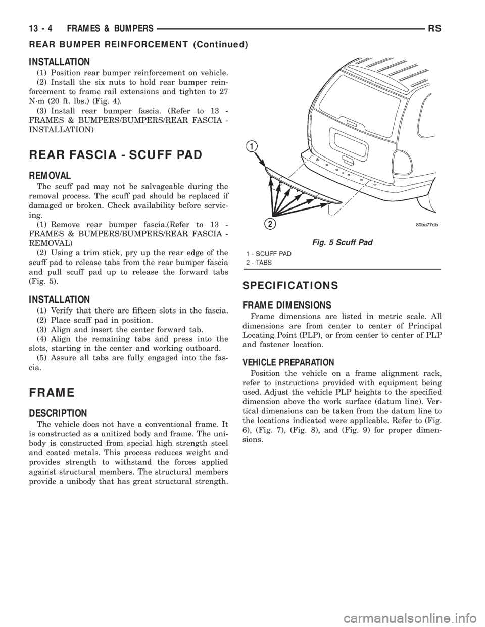
(Fig. 5).
INSTALLATION
(1) Verify that there are fifteen slots in the fascia.
(2) Place scuff pad in position.
(3) Align and insert the center forward tab.
(4) Align the remaining tabs and press into the
slots, starting in the center and working outboard.
(5) Assure all tabs are fully engaged into the fas-
cia.
FRAME
DESCRIPTION
The vehicle does not have a conventional frame. It
is constructed as a unitized body and frame. The uni-
body is constructed from special high strength steel
and coated metals. This process reduces weight and
provides strength to withstand the forces applied
against structural members. The structural members
provide a unibody that has great structural strength.
SPECIFICATIONS
FRAME DIMENSIONS
Frame dimensions are listed in metric scale. All
dimensions are from center to center of Principal
Locating Point (PLP), or from center to center of PLP
and fastener location.
VEHICLE PREPARATION
Position the vehicle on a frame alignment rack,
refer to instructions provided with equipment being
used. Adjust the vehicle PLP heights to the specified
dimension above the work surface (datum line). Ver-
tical dimensions can be taken from the datum line to
the locations indicated were applicable. Refer to (Fig.
6), (Fig. 7), (Fig. 8), and (Fig. 9) for proper dimen-
sions.
Fig. 5 Scuff Pad
1 - SCUFF PAD
2 - TABS
13 - 4 FRAMES & BUMPERSRS
REAR BUMPER REINFORCEMENT (Continued)
Page 3530 of 4284
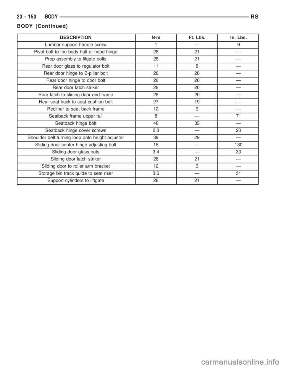
DESCRIPTION N´m Ft. Lbs. In. Lbs.
Lumbar support handle screw 1 Ð 9
Pivot bolt to the body half of hood hinge 28 21 Ð
Prop assembly to lifgate bolts 28 21 Ð
Rear door glass to regulator bolt 11 8 Ð
Rear door hinge to B-pillar bolt 28 20 Ð
Rear door hinge to door bolt 28 20 Ð
Rear door latch striker 28 20 Ð
Rear latch to sliding door end frame 28 20 Ð
Rear seat back to seat cushion bolt 27 19 Ð
Recliner to seat back frame 12 9 Ð
Seatback frame upper rail 8 Ð 71
Seatback hinge bolt 48 35 Ð
Seatback hinge cover screws 2.3 Ð 20
Shoulder belt turning loop onto height adjuster 39 29 Ð
Sliding door center hinge adjusting bolt 15 Ð 130
Sliding door glass nuts 3.4 Ð 30
Sliding door latch striker 28 21 Ð
Sliding door to roller arm bracket 12 9 Ð
Storage bin track quide to seat riser 3.5 Ð 31
Support cylinders to liftgate 28 21 Ð
23 - 150 BODYRS
BODY (Continued)
Page 3551 of 4284
(8) Install center roller channel end cover (Fig. 16).
(9) Install center stop on sliding door. (Refer to 23
- BODY/DOORS - SLIDING/STOP BUMPER -
INSTALLATION)
(10) Place upper roller stop bumper in position on
upper roller arm.
(11) Install screw to hold upper roller arm stop
bumper to upper roller arm (Fig. 14).
(12) Remove masking tape from body surfaces.
(13) Verify door operation and fit. Adjust as neces-
sary. (Refer to 23 - BODY/DOORS - SLIDING/SLID-
ING DOOR - ADJUSTMENTS)
SLIDING DOOR ADJUSTMENTS
NOTE: For power sliding door procedures refer to
POWER SLIDING DOOR SYSTEM in the ELECTRI-
CAL section.
PRELIMINARY CHECKS
(1) Close the sliding door, visually checking C-post
striker alignment entry into latch. Striker at this
point must not affect alignment. Striker should go
straight into the latching mechanism.
(2) On vehicles with left sliding doors, check the
fuel door blocker striker entry into latch. Striker at
this point must not affect alignment.
(3) Check C-post and B-post for door to aperture
gaps and door to door gaps. All gaps should be 5 mm
1 mm.
(4) Check door for height using character lines as
a reference. Also check roof contour as a controlling
factor.
Using the procedures noted below, adjust the side
door in the order the individual steps are called out.
DOOR FLUSHNESS ADJUSTMENT
(1) Check sliding door flushness at the C-pillar
striker.
(2) Adjust the C-pillar striker in or out untill the
door is flush.
(3) Check upper B-pillar flushness to A-pillar
cover.
(4) Loosen one nut on upper hinge and adjust door
in or out untill the door is flush.
(5) Check flushness at upper C-pillar.
(6) If upper C-pillar flushness is out of specifica-
tion use a heavy rubber malet on the door assembly
until door is in spec.
DOOR GAP ADJUSTMENT - UP/DOWN
UP/DOWN ADJUSTMENT
(1) Visually inspect the sliding door for fitting low
at the top of the door by checking the alignment of
the top contour of the door to the quarter panel.(2) Fully open the sliding door.
(3) Verify that all center hinge bolts are tight.
(4) Adjust the rear of the sliding door up by turn-
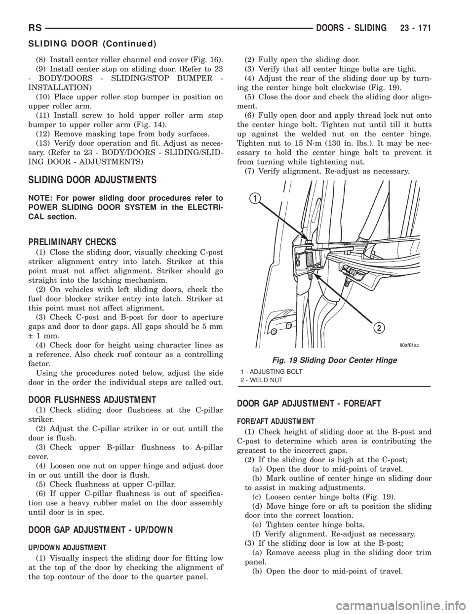
ing the center hinge bolt clockwise (Fig. 19).
(5) Close the door and check the sliding door align-
ment.
(6) Fully open door and apply thread lock nut onto
the center hinge bolt. Tighten nut until till it butts
up against the welded nut on the center hinge.
Tighten nut to 15 N´m (130 in. lbs.). It may be nec-
essary to hold the center hinge bolt to prevent it
from turning while tightening nut.
(7) Verify alignment. Re-adjust as necessary.
DOOR GAP ADJUSTMENT - FORE/AFT
FORE/AFT ADJUSTMENT
(1) Check height of sliding door at the B-post and
C-post to determine which area is contributing the
greatest to the incorrect gaps.
(2) If the sliding door is high at the C-post;
(a) Open the door to mid-point of travel.
(b) Mark outline of center hinge on sliding door
to assist in making adjustments.
(c) Loosen center hinge bolts (Fig. 19).
(d) Move hinge fore or aft to position the sliding
door into the correct location.
(e) Tighten center hinge bolts.
(f) Verify alignment. Re-adjust as necessary.
(3) If the sliding door is low at the B-post;
(a) Remove access plug in the sliding door trim
panel.
(b) Open the door to mid-point of travel.
Fig. 19 Sliding Door Center Hinge
1 - ADJUSTING BOLT
2 - WELD NUT
RSDOORS - SLIDING23 - 171
SLIDING DOOR (Continued)
Page 3579 of 4284
HOOD
TABLE OF CONTENTS
page page
HINGE
REMOVAL.............................199
INSTALLATION..........................199
HOOD
REMOVAL.............................200
INSTALLATION..........................200
LATCH
REMOVAL.............................200INSTALLATION..........................200
LATCH RELEASE CABLE
REMOVAL.............................201
INSTALLATION..........................201
LATCH STRIKER
REMOVAL.............................201
INSTALLATION..........................201
HINGE
REMOVAL
(1) Remove hood.
(2) Remove wiper unit. Refer to Group 8K, Wind-
shield Wipers and Washers, for procedure.
(3) Mark all bolt and hinge attachment locations
with a grease pencil or other suitable device to pro-
vide reference marks for installation.
(4) Remove pivot bolt from the body half of hood
hinge.
(5) Remove bolts attaching body half of hood hinge
to front fender flange and remove hinge from vehicle
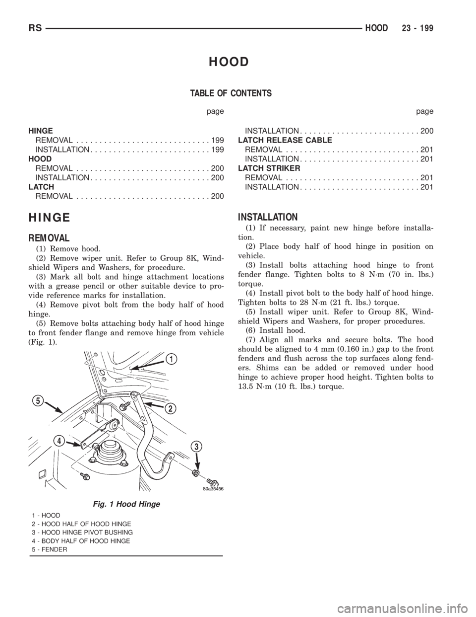
(Fig. 1).
INSTALLATION
(1) If necessary, paint new hinge before installa-
tion.
(2) Place body half of hood hinge in position on
vehicle.
(3) Install bolts attaching hood hinge to front
fender flange. Tighten bolts to 8 N´m (70 in. lbs.)
torque.
(4) Install pivot bolt to the body half of hood hinge.
Tighten bolts to 28 N´m (21 ft. lbs.) torque.
(5) Install wiper unit. Refer to Group 8K, Wind-
shield Wipers and Washers, for proper procedures.
(6) Install hood.
(7) Align all marks and secure bolts. The hood
should be aligned to 4 mm (0.160 in.) gap to the front
fenders and flush across the top surfaces along fend-
ers. Shims can be added or removed under hood
hinge to achieve proper hood height. Tighten bolts to
13.5 N´m (10 ft. lbs.) torque.
Fig. 1 Hood Hinge
1 - HOOD
2 - HOOD HALF OF HOOD HINGE
3 - HOOD HINGE PIVOT BUSHING
4 - BODY HALF OF HOOD HINGE
5 - FENDER
RSHOOD23 - 199
Page 3590 of 4284
(5) Remove screw attaching lower trim cover to
B-pillar from below seat belt retractor.
(6) Disengage hidden clips attaching lower trim
cover to B-pillar.
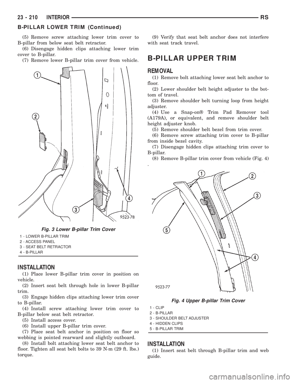
(7) Remove lower B-pillar trim cover from vehicle.
INSTALLATION
(1) Place lower B-pillar trim cover in position on
vehicle.
(2) Insert seat belt through hole in lower B-pillar
trim.
(3) Engage hidden clips attaching lower trim cover
to B-pillar.
(4) Install screw attaching lower trim cover to
B-pillar below seat belt retractor.
(5) Install access cover.
(6) Install upper B-pillar trim cover.
(7) Place seat belt anchor in position on floor so
webbing is pointed rearward and slightly outboard.
(8) Install bolt attaching lower seat belt anchor to
floor. Tighten all seat belt bolts to 39 N´m (29 ft. lbs.)
torque.(9) Verify that seat belt anchor does not interfere
with seat track travel.
B-PILLAR UPPER TRIM
REMOVAL
(1) Remove bolt attaching lower seat belt anchor to
floor.
(2) Lower shoulder belt height adjuster to the bot-
tom of travel.
(3) Remove shoulder belt turning loop from height
adjuster.
(4) Use a Snap-onž Trim Pad Remover tool
(A179A), or equivalent, and remove shoulder belt
height adjuster knob.
(5) Remove shoulder belt bezel from trim cover.
(6) Remove screw attaching trim cover to B-pillar
from inside bezel cavity.
(7) Disengage hidden clips attaching trim cover to
B-pillar.
(8) Remove B-pillar trim cover from vehicle (Fig. 4)
.
INSTALLATION
(1) Insert seat belt through B-pillar trim and web
guide.
Fig. 3 Lower B-pillar Trim Cover
1 - LOWER B-PILLAR TRIM
2 - ACCESS PANEL
3 - SEAT BELT RETRACTOR
4 - B-PILLAR
Fig. 4 Upper B-pillar Trim Cover
1 - CLIP
2 - B-PILLAR
3 - SHOULDER BELT ADJUSTER
4 - HIDDEN CLIPS
5 - B-PILLAR TRIM
23 - 210 INTERIORRS
B-PILLAR LOWER TRIM (Continued)
Page 3591 of 4284
(2) Place B-pillar trim cover in position on vehicle.
(3) Engage hidden clips attaching trim cover to
B-pillar.
(4) Install screw attaching trim cover to B-pillar
inside bezel cavity.
(5) Install shoulder belt bezel into trim cover.
(6) Install height adjuster knob.
(7) Install shoulder belt turning loop onto height
adjuster. Tighten bolt to 39 N´m (29 ft. lbs.) torque.
(8) Place seat anchor in position on floor so web-
bing is pointed rearward and slightly outboard.
(9) Install bolt attaching lower seat belt anchor to
floor. Tighten seat belt bolt to 39 N´m (29 ft. lbs.)
torque.
CARPETS AND FLOOR MATS
REMOVAL
(1) Remove front seats. (Refer to 23 - BODY/
SEATS/SEAT - REMOVAL).
(2) Remove front center console.
(3) Remove the remaining seats. Refer to the Own-
er's Manual for the proper procedures.
(4) Remove front cowl panels and sill plates.
(5) Remove sliding door sill plates. (Refer to 23 -
BODY/INTERIOR/SLIDING DOOR SILL PLATE -
REMOVAL).
(6) Remove the cargo organizer, if equipped.
(7) Remove liftgate scuff plate. (Refer to 23 -
BODY/INTERIOR/LIFTGATE SCUFF PLATE -
REMOVAL).
(8) Remove lower B-pillar trim covers.
(9) Remove D-pillar trim covers.
(10) Remove Quarter trim panels.
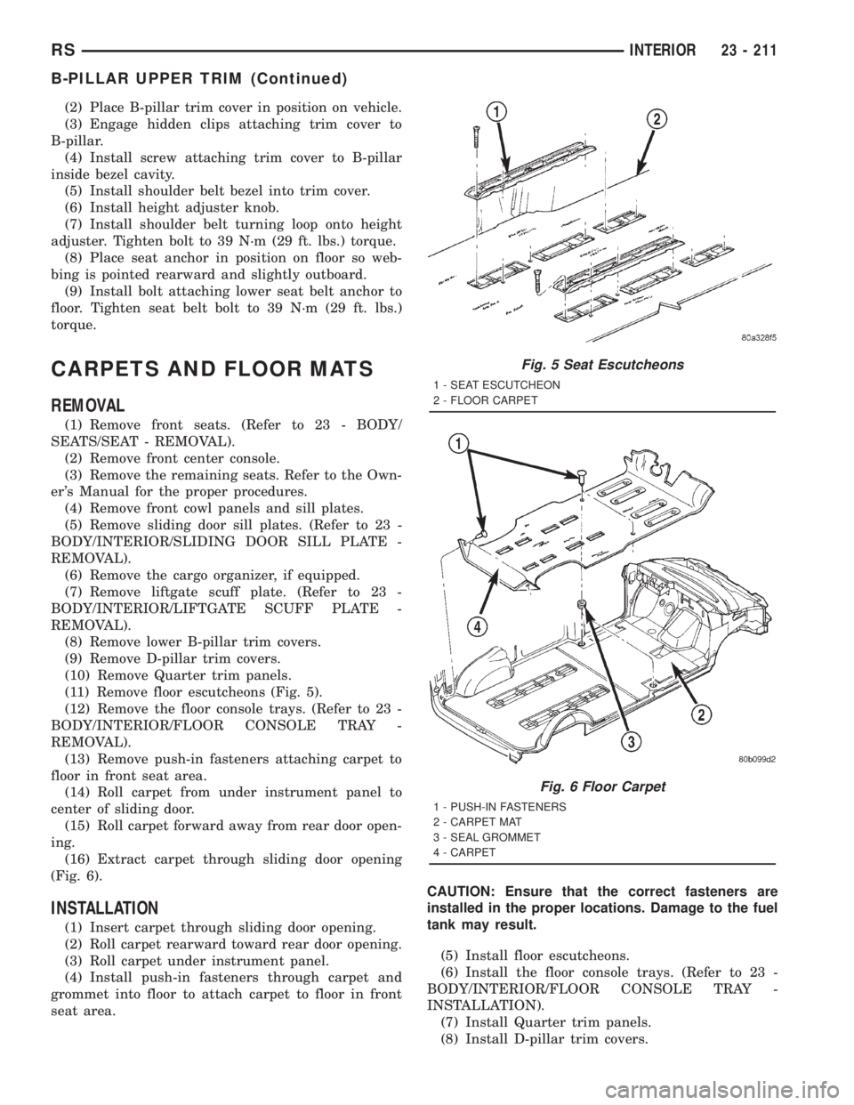
(11) Remove floor escutcheons (Fig. 5).
(12) Remove the floor console trays. (Refer to 23 -
BODY/INTERIOR/FLOOR CONSOLE TRAY -
REMOVAL).
(13) Remove push-in fasteners attaching carpet to
floor in front seat area.
(14) Roll carpet from under instrument panel to
center of sliding door.
(15) Roll carpet forward away from rear door open-
ing.
(16) Extract carpet through sliding door opening
(Fig. 6).
INSTALLATION
(1) Insert carpet through sliding door opening.
(2) Roll carpet rearward toward rear door opening.
(3) Roll carpet under instrument panel.
(4) Install push-in fasteners through carpet and
grommet into floor to attach carpet to floor in front
seat area.CAUTION: Ensure that the correct fasteners are
installed in the proper locations. Damage to the fuel
tank may result.
(5) Install floor escutcheons.
(6) Install the floor console trays. (Refer to 23 -
BODY/INTERIOR/FLOOR CONSOLE TRAY -
INSTALLATION).
(7) Install Quarter trim panels.
(8) Install D-pillar trim covers.
Fig. 5 Seat Escutcheons
1 - SEAT ESCUTCHEON
2 - FLOOR CARPET
Fig. 6 Floor Carpet
1 - PUSH-IN FASTENERS
2 - CARPET MAT
3 - SEAL GROMMET
4 - CARPET
RSINTERIOR23 - 211
B-PILLAR UPPER TRIM (Continued)