2001 CHRYSLER VOYAGER air condition
[x] Cancel search: air conditionPage 1017 of 4284
Verification Tests
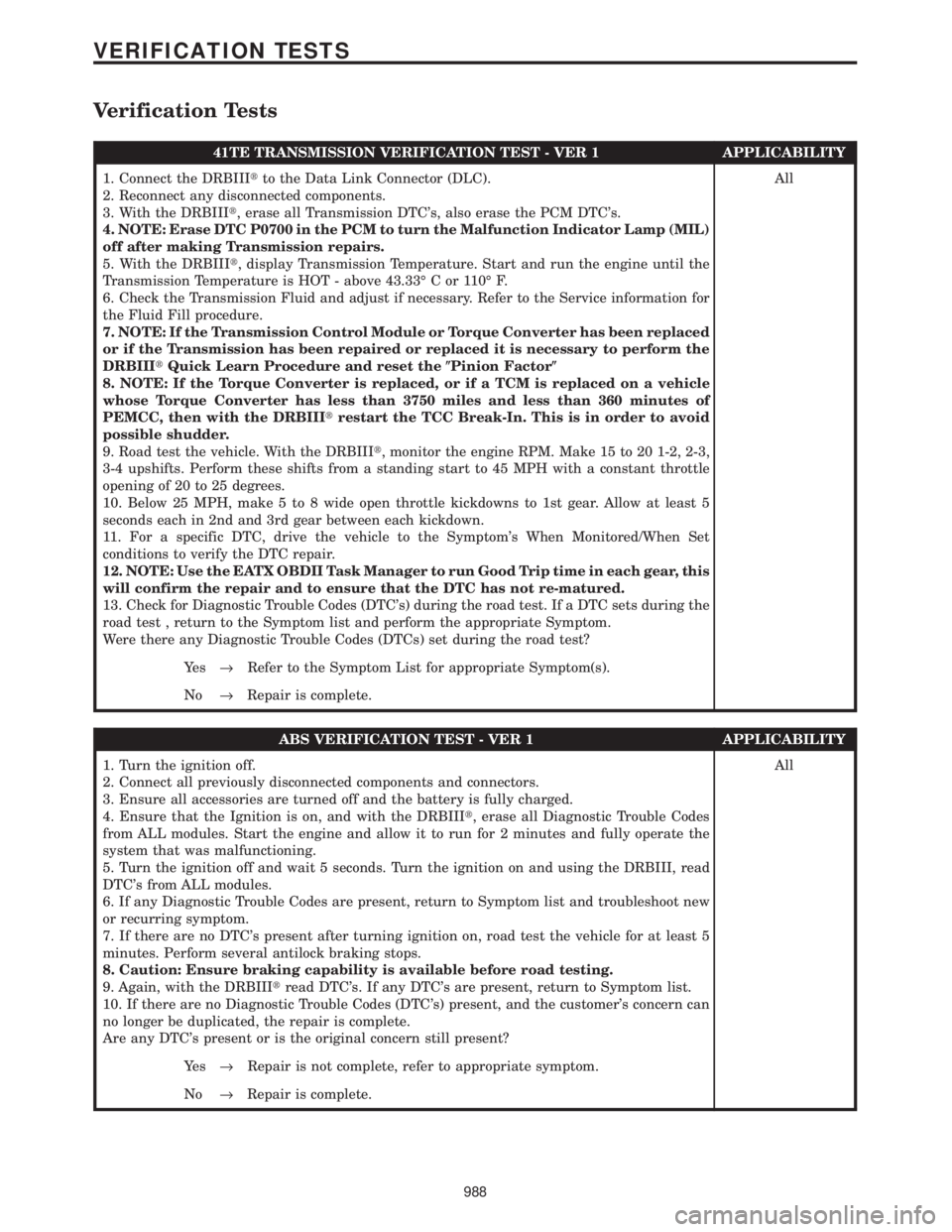
41TE TRANSMISSION VERIFICATION TEST - VER 1 APPLICABILITY
1. Connect the DRBIIItto the Data Link Connector (DLC).
2. Reconnect any disconnected components.
3. With the DRBIIIt, erase all Transmission DTC's, also erase the PCM DTC's.
4. NOTE: Erase DTC P0700 in the PCM to turn the Malfunction Indicator Lamp (MIL)
off after making Transmission repairs.
5. With the DRBIIIt, display Transmission Temperature. Start and run the engine until the
Transmission Temperature is HOT - above 43.33É C or 110É F.
6. Check the Transmission Fluid and adjust if necessary. Refer to the Service information for
the Fluid Fill procedure.
7. NOTE: If the Transmission Control Module or Torque Converter has been replaced
or if the Transmission has been repaired or replaced it is necessary to perform the
DRBIIItQuick Learn Procedure and reset the(Pinion Factor(
8. NOTE: If the Torque Converter is replaced, or if a TCM is replaced on a vehicle
whose Torque Converter has less than 3750 miles and less than 360 minutes of
PEMCC, then with the DRBIIItrestart the TCC Break-In. This is in order to avoid
possible shudder.
9. Road test the vehicle. With the DRBIIIt, monitor the engine RPM. Make 15 to 20 1-2, 2-3,
3-4 upshifts. Perform these shifts from a standing start to 45 MPH with a constant throttle
opening of 20 to 25 degrees.
10. Below 25 MPH, make 5 to 8 wide open throttle kickdowns to 1st gear. Allow at least 5
seconds each in 2nd and 3rd gear between each kickdown.
11. For a specific DTC, drive the vehicle to the Symptom's When Monitored/When Set
conditions to verify the DTC repair.
12. NOTE: Use the EATX OBDII Task Manager to run Good Trip time in each gear, this
will confirm the repair and to ensure that the DTC has not re-matured.
13. Check for Diagnostic Trouble Codes (DTC's) during the road test. If a DTC sets during the
road test , return to the Symptom list and perform the appropriate Symptom.
Were there any Diagnostic Trouble Codes (DTCs) set during the road test?All
Ye s®Refer to the Symptom List for appropriate Symptom(s).
No®Repair is complete.
ABS VERIFICATION TEST - VER 1 APPLICABILITY
1. Turn the ignition off.
2. Connect all previously disconnected components and connectors.
3. Ensure all accessories are turned off and the battery is fully charged.
4. Ensure that the Ignition is on, and with the DRBIIIt, erase all Diagnostic Trouble Codes
from ALL modules. Start the engine and allow it to run for 2 minutes and fully operate the
system that was malfunctioning.
5. Turn the ignition off and wait 5 seconds. Turn the ignition on and using the DRBIII, read
DTC's from ALL modules.
6. If any Diagnostic Trouble Codes are present, return to Symptom list and troubleshoot new
or recurring symptom.
7. If there are no DTC's present after turning ignition on, road test the vehicle for at least 5
minutes. Perform several antilock braking stops.
8. Caution: Ensure braking capability is available before road testing.
9. Again, with the DRBIIItread DTC's. If any DTC's are present, return to Symptom list.
10. If there are no Diagnostic Trouble Codes (DTC's) present, and the customer's concern can
no longer be duplicated, the repair is complete.
Are any DTC's present or is the original concern still present?All
Ye s®Repair is not complete, refer to appropriate symptom.
No®Repair is complete.
988
VERIFICATION TESTS
Page 1018 of 4284
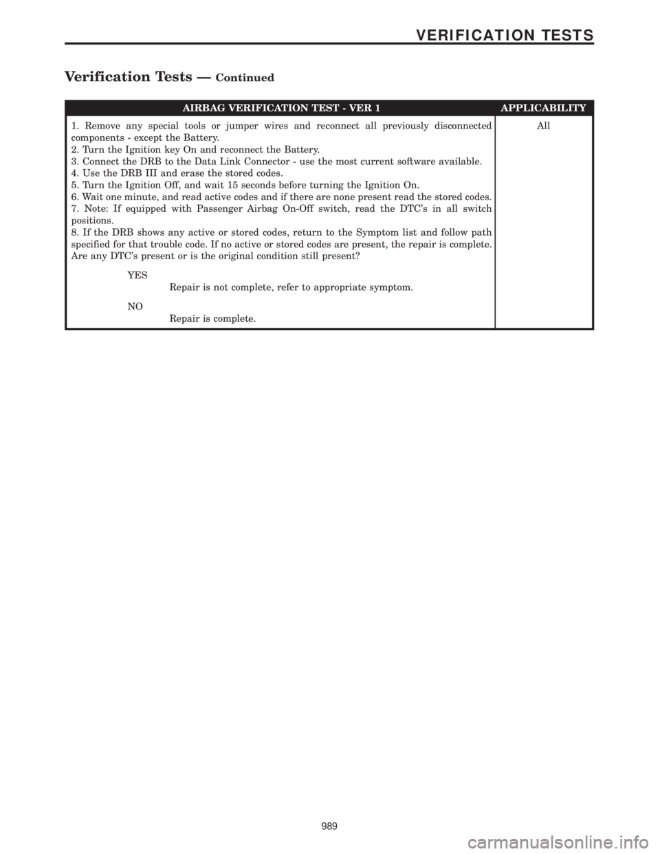
AIRBAG VERIFICATION TEST - VER 1 APPLICABILITY
1. Remove any special tools or jumper wires and reconnect all previously disconnected
components - except the Battery.
2. Turn the Ignition key On and reconnect the Battery.
3. Connect the DRB to the Data Link Connector - use the most current software available.
4. Use the DRB III and erase the stored codes.
5. Turn the Ignition Off, and wait 15 seconds before turning the Ignition On.
6. Wait one minute, and read active codes and if there are none present read the stored codes.
7. Note: If equipped with Passenger Airbag On-Off switch, read the DTC's in all switch
positions.
8. If the DRB shows any active or stored codes, return to the Symptom list and follow path
specified for that trouble code. If no active or stored codes are present, the repair is complete.
Are any DTC's present or is the original condition still present?All
YES
Repair is not complete, refer to appropriate symptom.
NO
Repair is complete.
989
VERIFICATION TESTS
Verification Tests ÐContinued
Page 1019 of 4284
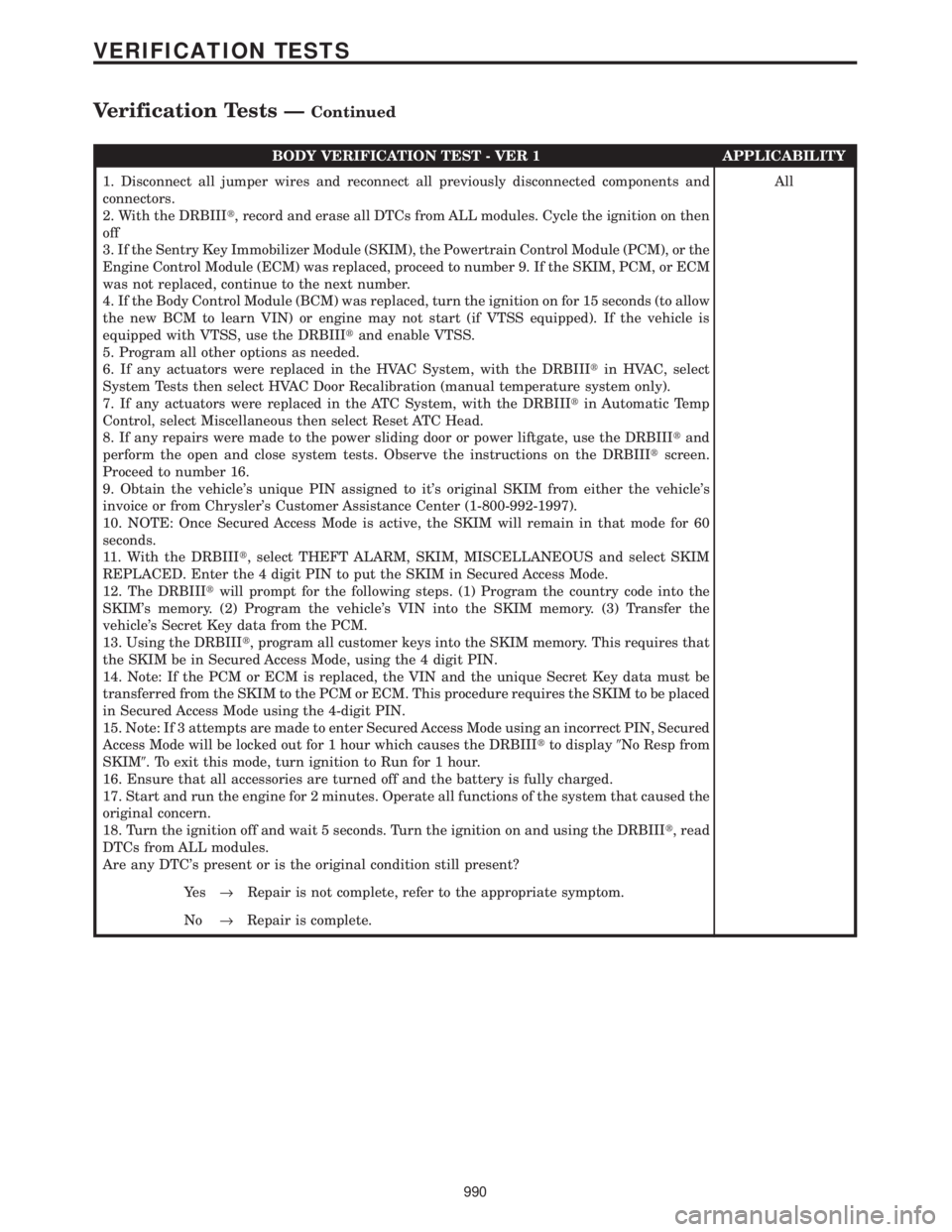
BODY VERIFICATION TEST - VER 1 APPLICABILITY
1. Disconnect all jumper wires and reconnect all previously disconnected components and
connectors.
2. With the DRBIIIt, record and erase all DTCs from ALL modules. Cycle the ignition on then
off
3. If the Sentry Key Immobilizer Module (SKIM), the Powertrain Control Module (PCM), or the
Engine Control Module (ECM) was replaced, proceed to number 9. If the SKIM, PCM, or ECM
was not replaced, continue to the next number.
4. If the Body Control Module (BCM) was replaced, turn the ignition on for 15 seconds (to allow
the new BCM to learn VIN) or engine may not start (if VTSS equipped). If the vehicle is
equipped with VTSS, use the DRBIIItand enable VTSS.
5. Program all other options as needed.
6. If any actuators were replaced in the HVAC System, with the DRBIIItin HVAC, select
System Tests then select HVAC Door Recalibration (manual temperature system only).
7. If any actuators were replaced in the ATC System, with the DRBIIItin Automatic Temp
Control, select Miscellaneous then select Reset ATC Head.
8. If any repairs were made to the power sliding door or power liftgate, use the DRBIIItand
perform the open and close system tests. Observe the instructions on the DRBIIItscreen.
Proceed to number 16.
9. Obtain the vehicle's unique PIN assigned to it's original SKIM from either the vehicle's
invoice or from Chrysler's Customer Assistance Center (1-800-992-1997).
10. NOTE: Once Secured Access Mode is active, the SKIM will remain in that mode for 60
seconds.
11. With the DRBIIIt, select THEFT ALARM, SKIM, MISCELLANEOUS and select SKIM
REPLACED. Enter the 4 digit PIN to put the SKIM in Secured Access Mode.
12. The DRBIIItwill prompt for the following steps. (1) Program the country code into the
SKIM's memory. (2) Program the vehicle's VIN into the SKIM memory. (3) Transfer the
vehicle's Secret Key data from the PCM.
13. Using the DRBIIIt, program all customer keys into the SKIM memory. This requires that
the SKIM be in Secured Access Mode, using the 4 digit PIN.
14. Note: If the PCM or ECM is replaced, the VIN and the unique Secret Key data must be
transferred from the SKIM to the PCM or ECM. This procedure requires the SKIM to be placed
in Secured Access Mode using the 4-digit PIN.
15. Note: If 3 attempts are made to enter Secured Access Mode using an incorrect PIN, Secured
Access Mode will be locked out for 1 hour which causes the DRBIIItto display9No Resp from
SKIM9. To exit this mode, turn ignition to Run for 1 hour.
16. Ensure that all accessories are turned off and the battery is fully charged.
17. Start and run the engine for 2 minutes. Operate all functions of the system that caused the
original concern.
18. Turn the ignition off and wait 5 seconds. Turn the ignition on and using the DRBIIIt, read
DTCs from ALL modules.
Are any DTC's present or is the original condition still present?All
Ye s®Repair is not complete, refer to the appropriate symptom.
No®Repair is complete.
990
VERIFICATION TESTS
Verification Tests ÐContinued
Page 1020 of 4284
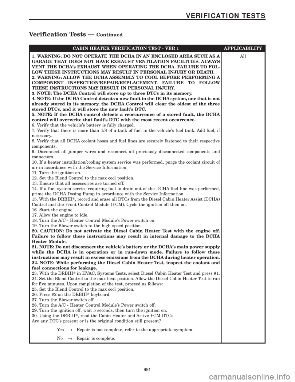
CABIN HEATER VERIFICATION TEST - VER 1 APPLICABILITY
1. WARNING: DO NOT OPERATE THE DCHA IN AN ENCLOSED AREA SUCH AS A
GARAGE THAT DOES NOT HAVE EXHAUST VENTILATION FACILITIES. ALWAYS
VENT THE DCHA's EXHAUST WHEN OPERATING THE DCHA. FAILURE TO FOL-
LOW THESE INSTRUCTIONS MAY RESULT IN PERSONAL INJURY OR DEATH.
2. WARNING: ALLOW THE DCHA ASSEMBLY TO COOL BEFORE PERFORMING A
COMPONENT INSPECTION/REPAIR/REPLACEMENT. FAILURE TO FOLLOW
THESE INSTRUCTIONS MAY RESULT IN PERSONAL INJURY.
3. NOTE: The DCHA Control will store up to three DTCs in its memory.
4. NOTE: If the DCHA Control detects a new fault in the DCHA system, one that is not
already stored in its memory, the DCHA Control will clear the oldest of the three
stored DTCs, and it will store the new fault's DTC.
5. NOTE: If the DCHA control detects a reoccurrence of a stored fault, the DCHA
control will overwrite that fault's DTC with the most recent occurrence.
6. Verify that the vehicle's battery is fully charged.
7. Verify that there is more than 1/8 of a tank of fuel in the vehicle's fuel tank. Add fuel, if
necessary.
8. Verify that all DCHA coolant hoses and fuel lines are securely fastened to their respective
components.
9. Disconnect all jumper wires and reconnect all previously disconnected components and
connectors.
10. If a heater installation/cooling system service was performed, purge the coolant circuit of
air in accordance with the Service Information.
11. Turn the ignition on.
12. Set the Blend Control to the max cool position.
13. Ensure that all accessories are turned off.
14. If a fuel system service requiring fuel to drain out of the DCHA fuel line was performed,
prime the DCHA Dosing Pump in accordance with the Service Information.
15. With the DRBIIIt, record and erase all DTCs from the Diesel Cabin Heater Assist (DCHA)
Control and the Front Control Module (FCM). Cycle the ignition off then on.
16. Start the engine.
17. Allow the engine to idle.
18. Turn the A/C - Heater Control Module's Power switch on.
19. Turn the Blower switch to the high speed position.
20. CAUTION: Do not activate the Diesel Cabin Heater Test with the engine off.
Failure to follow these instructions may result in internal damage to the DCHA
Heater Module.
21. NOTE: Do not disconnect the vehicle's battery or the DCHA's main power supply
while the DCHA is in operation or in run-down mode. Failure to follow these
instructions may result in excess emissions from the DCHA during heater operation.
22. NOTE: While performing the Diesel Cabin Heater Test, inspect the coolant and
fuel connections for leakage.
23. With the DRBIIItin HVAC, Systems Tests, select Diesel Cabin Heater Test and press #1.
24. Set the Blend Control to the max heat position. Allow the Diesel Cabin Heater Test to run
for five minutes. Upon completion of the test, proceed as follows:
25. Set the Blend Control to the max cool position.
26. Press #2 on the DRBIIItkeyboard.
27. Turn the Blower switch off.
28. Turn the A/C - Heater Control Module's Power switch off.
29. Turn the ignition off, wait 5 seconds, then turn the ignition on.
30. Using the DRBIIIt, read the Cabin Heater and Active FCM DTCs.
Are any DTC's present or is the original condition still present?All
Ye s®Repair is not complete, refer to the appropriate symptom.
No®Repair is complete.
991
VERIFICATION TESTS
Verification Tests ÐContinued
Page 1021 of 4284
MEMORY SYSTEM VERIFICATION TEST - VER 1 APPLICABILITY
1. Reconnect all previously disconnected components and connectors.
2. If any Memory Seat Memory Module Trouble Codes are present, erase at this time.
3. With the Memory Switch on the Driver's Door, program the Driver's Seat #1 Button to a
desired position and Driver #2 Button to a different position.
4. Remove the Ignition Key and close all Doors to allow the Body Control Module to time out,
about 30 seconds.
5. Verify that both Memory positions can be recalled from the RKE transmitter and the
Memory Switch on the Driver's Door.
6. Turn the ignition on, and with the DRBIII, erase all Diagnostic Trouble Codes from ALL
modules. Start the engine and allow it to run for 2 minutes and fully operate the system that
was malfunctioning.
7. Turn the ignition off and wait 5 seconds. Turn the ignition on and using the DRBIII, read
DTC's from ALL modules.
Are any DTC's present or is the original complaint still present?All
Ye s®Repair is not complete, refer to appropriate symptom.
No®Repair is complete.
POWERTRAIN VERIFICATION TEST VER - 1 APPLICABILITY
1. NOTE: If the PCM has been replaced and the correct VIN and mileage have not
been programmed, a DTC will be set in the ABS Module, Airbag Module and the
SKIM.
2. NOTE: If the vehicle is equipped with a Sentry Key Immobilizer System, Secret
Key data must be updated. Refer to the Service Information for the PCM, SKIM and
the Transponder (ignition key) for programming information.
3. Inspect the vehicle to ensure that all components related to the repair are connected
properly.
4. Inspect the engine oil for fuel contamination. Replace the oil and filter as necessary.
5. Attempt to start the engine.
6. If the No Start condition is still present, refer to the symptom list and perform the diagnostic
testing as necessary. refer to and Technical Service Bulletins that may apply.
7. Run the engine for one warm-up cycle to verify operation.
8. With the DRBIIIt, confirm that no DTCs or Secondary Indicators are present and that all
components are functioning properly.
9. If a DTC is present, refer to the appropriate category and select the corresponding symptom.
Are any DTCs present?All
Ye s®Repair is not complete, refer to appropriate symptom.
No®Repair is complete.
992
VERIFICATION TESTS
Verification Tests ÐContinued
Page 1158 of 4284
1.0 INTRODUCTION
The procedures contained in this manual include
all the specifications, instructions, and graphics
needed to diagnose Mark 20 Antilock Braking Sys-
tem (ABS) and Mark 20 Antilock Braking System
with Traction Control. The diagnostics in this man-
ual are based on the failure condition or symptom
being present at time of diagnosis.
Please follow the recommendations below when
choosing your diagnostic path.
1. First make sure the DRBIIItis communicating
with the CAB. If the DRBIIItdisplays a ªNo
Responseº condition, you must diagnose that
first.
2. Read DTC's (diagnostic trouble codes) with the
DRBIIIt.
3. If no DTC's are present, identify the customer
complaint.
4. Once the DTC or customer complaint is identi-
fied, locate the matching test in the Table of
Contents and begin to diagnose the symptom.
All component location views are in Section 8.0.
All connector pinouts are in Section 9.0. All sche-
matics are in Section 10.0.
An * placed before the symptom description indi-
cates a concern with no associated DTC.
When repairs are required, refer to the appropri-
ate service manual for the proper removal and
repair procedure.
Diagnostic procedures change every year. New
diagnostic systems may be added; carry over sys-
tems may be enhanced. READ THIS MANUAL
BEFORE TRYING TO DIAGNOSE A VEHICLE
CODE. It is recommended that you review the
entire manual to become familiar with all new and
changed diagnostic procedures.
After using this book, if you have any comments
or recommendations, please fill out the form at the
back of the book and mail it back to us.
1.1 SYSTEM COVERAGE
This diagnostic procedure manual covers the an-
tilock braking system (ABS) and traction control
system found on: 2001 Chrysler Town and Country,
Dodge Caravan and Grand Caravan.
1.2 SIX-STEP TROUBLESHOOTING
PROCEDURE
Diagnosis of the controller antilock brake module
is done in six basic steps:
²verification of complaint
²verification of any related symptoms
²symptom analysis
²problem isolation
²repair of isolated problem
²verification of proper operation
2.0 IDENTIFICATION OF
SYSTEM
Vehicles equipped with the Teves Mark 20 an-
tilock brake system can be identified by the pres-
ence of the controller antilock brake module located
beneath the master cylinder.
3.0 SYSTEM DESCRIPTION AND
FUNCTIONAL OPERATION
3.1 TEVES MARK 20 SYSTEM
DESCRIPTION
The controller antilock brake module is used to
monitor wheel speeds and to modulate (control)
hydraulic pressure in each brake channel. The
modulated hydraulic pressure is used to prevent
wheel lock-up during braking.
The Teves Mark 20 system uses a diagonal split
hydraulic brake system.
In the standard brake mode
the master cylinder primary circuit supplies pressure
to the right front and left rear wheel brakes, and the
secondary master cylinder circuit supplies pressure
to the left front and right rear wheel brakes.
3.2 TRACTION CONTROL SYSTEM (TCS)
DESCRIPTION
The main purpose of traction control is to reduce
wheel slip and maintain traction at the driven
wheels when road surfaces are slippery. The trac-
tion control system reduces wheel slip by braking
the wheel that is losing traction. The system is
designed to operate at speeds below 56 km/h (35
mph).
The Controller Antilock Brake (CAB) monitors
wheel speeds. If, during acceleration, the module
detects front (drive) wheel slip and the brakes are
not applied, the CAB will enter traction control
mode. Traction control works in the following order
when drive wheel slip is detected.
1. Close the (normally open) isolation valves.
2. Start pump/motor and supply volume/pressure
to front hydraulic circuits (pump runs continu-
ously during traction control).
3. Open and close build and decay valves to main-
tain minimum wheel slip and maximum trac-
tion.
1
GENERAL INFORMATION
Page 1160 of 4284
²three power feeds: valves, pump and microproces-
sor
²brake switch
²traction control switch
The CAB outputs include the following:
²ABS warning indicator actuation
²12 volts power to wheel speed sensors
²eight valves
²ten valves with traction control
²diagnostic communication
²PCI bus communication
²traction control lamp illumination
3.3.3 HYDRAULIC CONTROL UNIT
The hydraulic control unit (HCU) contains the
valve block assembly, two accumulators, and pump/
motor assembly. The HCU is attached to the CAB.
Valve Block Assembly:The valve block assem-
bly contains valves with four inlet valves and four
outlet valves. The inlet valves are spring-loaded in
the open position and the outlet valves are spring
loaded in the closed position. During an antilock
stop, these valves are cycled to maintain the proper
slip ratio for each wheel. If a wheel detects slip, the
inlet valve is closed to prevent and further pressure
increase. Then the outlet valve is opened to release
the pressure to the accumulators until the wheel is
no longer slipping. Once the wheel is no longer
slipping, the outlet valve is closed and the inlet
valve is opened to reapply pressure. If the wheel is
decelerating within its predetermined limits (prop-
er slip ratio), the inlet valve will close to hold the
pressure constant. On vehicles which are equipped
with a traction control system, there are two addi-
tional valves that isolate the master cylinder and
rear wheels. During a traction control event the
brakes are applied to reduce wheel slippage.
Pump Motor Assembly:The pump motor as-
sembly provides the extra amount of fluid needed
during antilock braking. The pump is supplied fluid
that is released to the accumulators when the outlet
valve is opened during an antilock stop. The pump
is also used to drain the accumulator circuits after
the antilock stop is complete. The pump is operated
by an integral electric motor. This DC-type motor is
controlled by the CAB. The CAB may turn on the
pump motor when an antilock stop is detected. The
pump continues to run during the antilock stop and
is turned off after the stop is complete. Under some
conditions, the pump motor will run to drain the
accumulators during the next drive off. The CAB
monitors the pump motor operation internally.
Accumulators:The accumulators provide tem-
porary fluid storage during an antilock stop and are
drained by the pump motor.
3.3.4 SWITCHES/SENSORS
Master Cylinder:The master cylinder is a stan-
dard tandem compensating port design for ABS and
non ABS systems. Traction control vehicles use a
dual center port master cylinder. For proper trac-
tion control operation the standard master cylinder
must not be used.
A fluid level switch is located in the master
cylinder fluid reservoir. The switch closes when a
low fluid level is detected. The fluid level switch
turns on the brake warning indicator by grounding
the indicator circuit. This switch does not disable
the ABS system.
Wheel Speed Sensors and Tone Wheels:One
active wheel speed sensor (WSS) is located at each
wheel and sends a small signal to the control
module (CAB). This signal is generated when a
toothed sensor ring (tone wheel) passes by a station-
ary wheel speed sensor. The CAB converts the
signals into digital signals for each wheel.
Because of internal circuitry, correct wheel speed
sensor function cannot be determined by a continu-
ity or resistance check through the sensor.
The front wheel speed sensor is attached to a boss
in the steering knuckle. The tone wheel is an
integral part of the front axle shaft. The rear speed
sensor is mounted though the bearing cover and the
rear tone wheel is an integral part of the rear
bearing hub. The wheel speed sensor air gap is not
adjustable. Refer to the service manual for wheel
speed sensor air gap and resistance specifications.
The four wheel speed sensors are serviced indi-
vidually. The front tone wheels are serviced as an
assembly with the outer constant velocity (C.V.)
joint housing. The rear tone wheels are serviced as
an assembly.
Correct antilock system operation is dependent
on tone wheel speed signals from the wheel speed
sensors. The vehicle's wheels and tires should all be
the same size and type to generate accurate signals.
In addition, the tires should be inflated to the
recommended pressure for optimum system opera-
tion. Variation in wheel and tire size or significant
variations in inflation pressure can produce inaccu-
rate wheel speed signals; however, the system will
continue to function when using the mini-spare.
3.3.5 SYSTEM INITIALIZATION
System initialization starts when the key is
turned to ªrunº. At this point, the CAB performs a
complete self-check of all electrical components in
the antilock systems.
Between 8-17 km/h (5-10 mph), a dynamic test is
performed. This will momentarily cycle the inlet
and outlet valves, check wheel speed sensor cir-
cuitry, and run the pump motor at 25 km/h (15
mph). The CAB will try to test the pump motor. If
3
GENERAL INFORMATION
Page 1163 of 4284
4.3 WARNINGS
4.3.1 VEHICLE DAMAGE WARNINGS
Before disconnecting any control module, make
sure the ignition is ``off ''. Failure to do so could
damage the module.
When testing voltage or continuity at any control
module, use the terminal side (not the wire end) of
the connector. Do not probe a wire through the
insulation, this will damage it and eventually cause
it to fail because of corrosion.
Be careful when performing electrical tests so as
to prevent accidental shorting of terminals. Such
mistakes can damage fuses or components. Also, a
second code could be set, making diagnosis of the
original problem more difficult.
4.3.2 ROAD TESTING A COMPLAINT
VEHICLE
Some complaints will require a test drive as part
of the repair verification procedure. The purpose of
the test drive is to try to duplicate the diagnostic
code or symptom condition.
WARNING: BEFORE ROAD TESTING A
VEHICLE, BE SURE THAT ALL
COMPONENTS ARE REASSEMBLED.
DURING THE TEST DRIVE, DO NOT TRY TO
READ THE DRB SCREEN WHILE IN MOTION.
DO NOT HANG THE DRBIIITFROM THE
REAR VIEW MIRROR OR OPERATE IT
YOURSELF. HAVE AN ASSISTANT
AVAILABLE TO OPERATE THE DRBIIIT.
4.4 DIAGNOSIS
1. Your diagnostic test procedure must begin with a
thorough visual inspection of the ABS system for
damaged components or disconnected connec-
tors. The brake lamps must be operational, and
if they are not, repair them prior to continuing.
2. Connect the DRBIIItto the data link connector,
which is located under the dash to the left of the
steering column. If the DRBIIItdoes not power
up, check the power and ground supplies to the
connector.
3. Turn the ignition on. Select ªAntilock Brakesº. If
the DRBIIItdisplays ªNo Responseº condition
you must diagnose that first.
4. Read and record all ABS diagnostic trouble
codes. If the ªCAB Power Feed Circuitº diagnos-
tic trouble code is present, it must be repaired
prior to addressing any other DTC's. If any
additional DTC's are present, proceed to theappropriate test by locating the matching test in
the Table of Contents and begin to diagnose the
symptom.
5. If there are no diagnostic trouble codes present,
identify the customer complaint. Select ªInputs/
Outputsº and read the brake switch input as you
press and release the brake pedal. If the display
does not match the state of the pedal, perform
the proper test by locating the matching test in
the Table of Contents and begin to diagnose the
symptom. If a problem exists with the yellow
ªABSº warning indicator or the red ªBrakeº
indicator exists, refer to the proper tests by
locating the matching test in the Table of Con-
tents and begin to diagnose the symptom. Read
the traction control switch input as you press
and release the switch. If the display does not
match the state of the indicator perform the
proper test by locating the matching test in the
Table of Contents and begin to diagnose the
symptom.
6. If no other problems are found, it will be neces-
sary to road test the vehicle. Perform several
antilock stops from above 50 Km/h (30 mph) and
then repeat step 4. If any diagnostic trouble
codes are present, proceed to the appropriate test.
7. The following conditions should be considered
ªNORMALº operation, and no repairs should be
attempted to correct them.
± Brake pedal feedback during an ABS stop
(clicking, vibrating).
± Clicking, groaning or buzzing at 25 Km/h (15
mph) or 40 Km/h (24 mph) (drive off self test).
± Groaning noise during an ABS stop.
± Slight brake pedal drop and pop noise when
ignition is initially turned on.
± Brake pedal ratcheting down at the end of an
ABS stop.
8. If the complaint is ABS ªcyclingº at the end of a
stop at low speeds, it may be caused by a
marginal wheel speed sensor signal. The sensor
air gap, tone wheel condition, and/or brakes
hanging up are possible causes of this condition.
9. After a road test in which no problems were
found, refer to any Technical Service Bulletins
that may apply.
5.0 REQUIRED TOOLS AND
EQUIPMENT
DRBIIIt(diagnostic read-out box)
jumper wires
ohmmeter
voltmeter
test light
6
GENERAL INFORMATION