2001 CHRYSLER VOYAGER air condition
[x] Cancel search: air conditionPage 1168 of 4284
Symptom:
CAB INTERNAL FAILURE
When Monitored and Set Condition:
CAB INTERNAL FAILURE
When Monitored: Ignition on. The CAB monitors its internal microprocessors for correct
operation.
Set Condition: If the CAB detects an internal fault, the DTC is set.
POSSIBLE CAUSES
CAB - INTERNAL CONCERN
TEST ACTION APPLICABILITY
1 The only possible cause is a CAB internal concern.
If there are no possible causes remaining, view repair.All
View repair.
Replace the Controller Antilock Brake in accordance with the
Service Information.
Perform ABS VERIFICATION TEST - VER 1.
11
BRAKES (CAB)
Page 1187 of 4284
Symptom:
SYSTEM UNDERVOLTAGE
When Monitored and Set Condition:
SYSTEM UNDERVOLTAGE
When Monitored: Ignition on. The CAB monitors the Fused Ignition Switch Output
circuit voltage above 10 km/h (6 mph) every 7 milliseconds for proper system voltage.
Set Condition: If the voltage is below 9.5 volts, the Diagnostic Trouble Code (DTC) is set.
POSSIBLE CAUSES
BATTERY VOLTAGE LOW
INTERMITTENT DTC
FUSED IGNITION SWITCH OUTPUT CIRCUIT HIGH RESISTANCE
CAB - INTERNAL FAULT
TEST ACTION APPLICABILITY
1 Turn the ignition on.
With the DRBIIIt, erase DTC's.
Turn the ignition off.
Turn the ignition on.
Start the engine.
Drive the vehicle above 16 km/h (10 mph) for at least 20 seconds.
Stop the vehicle
With the DRBIIIt, read DTC's.
Does the DRBIIItdisplay System Undervoltage DTC?All
Ye s®Go To 2
No®Go To 5
2 Engine Running.
Measure the battery voltage.
Is the battery voltage below 10 volts?All
Ye s®Refer to appropriate service information for charging system
testing and repair.
Perform ABS VERIFICATION TEST - VER 1.
No®Go To 3
3 Disconnect the CAB harness connector.
Turn the ignition on.
Measure the voltage of the Fused Ignition Switch circuit.
Is the voltage above 10 volts?All
Ye s®Go To 4
No®Repair the Fused Ignition Switch Output Circuit for high resis-
tance
Perform ABS VERIFICATION TEST - VER 1.
30
BRAKES (CAB)
Page 1220 of 4284
1.0 INTRODUCTION
The procedures contained in this manual include
all the specifications, instructions and graphics
needed to diagnose engine control module (ECM)
and sentry key immobilizer system (SKIS) prob-
lems; they are no start, diagnostic trouble code
(DTC), and no trouble code problems for the ECM.
The diagnostics in this manual are based on the
trouble condition or symptom being present at the
time of diagnosis.
When repairs are required, refer to the appropri-
ate service information for the proper removal and
repair procedure.
Diagnostic procedures change every year. New
diagnostic systems may be added; carryover sys-
tems may be enhanced. IT IS RECOMMENDED
THAT YOU REVIEW THE ENTIRE MANUAL TO
BECOME FAMILIAR WITH ALL NEW AND
CHANGED DIAGNOSTIC PROCEDURES.
This manual is designed to begin all diagnosis at
the DTC TEST, which is located at the beginning of
Section 7.0. This will cover all the necessary re-
quirements to begin a logical diagnostic path for
each problem. If there is a diagnostic trouble code
(DTC) detected, it will direct you to the trouble code
test. If there are no DTCs present, it will direct you
by symptom to a no trouble code test.
This book reflects many suggested changes from
readers of past issues. After using this book, if you
have any comments or recommendations, please fill
out the form at the back of the book and mail it back
to us.
1.1 SYSTEM COVERAGE
This diagnostic procedures manual covers all
2001 RG body vehicles equipped with the 2.5L VM
diesel engine.
1.2 SIX-STEP TROUBLESHOOTING
PROCEDURE
Diagnosis of the engine control module (ECM)
and sentry key immobilizer system (SKIS) is done
in six basic steps:
²verification of complaint
²verification of any related symptom
²symptom analysis
²problem isolation
²repair of isolated problem
²verification of proper operation
NOTE: All tests in this manual should be per-
formed with the engine at operating temperature,
unless specified within a particular test.
2.0 IDENTIFICATION OF
SYSTEM
The ECM is located in the left side of the engine
compartment between the left front headlamp and
the intelligent power module. The sentry key immo-
bilizer module (SKIM) is located below the steering
column behind the steering wheel.
3.0 SYSTEM DESCRIPTION AND
FUNCTIONAL OPERATION
3.1 GENERAL DESCRIPTION
The 2.5L VM diesel engine system is equipped
with the latest in technical advances. The on-board
diagnostics incorporated in the engine control mod-
ule and SKIM are intended to assist the field
technician in repairing vehicle problems by the
quickest means.
The engine system incorporates a common rail
fuel delivery design. This design utilizes electroni-
cally controlled solenoid valve type fuel injectors.
Each injector is controlled individually by the ECM.
Injector timing and fuel quantity are controlled by
the ECM based on inputs from the various sensors.
The precision control of the injectors by the ECM
helps to reduce the engine noise, odor and smoke.
3.2 FUNCTIONAL OPERATION
3.2.1 ECM ON-BOARD DIAGNOSTICS
The ECM has been programmed to monitor many
different circuits of the diesel fuel injection system.
This monitoring is called on-board diagnostics.
Certain criteria must be met for a trouble code to
be entered into the ECM memory. The criteria may
be a range of: engine rpm, engine temperature, time
or other input signals to the ECM. If all of the
criteria for monitoring a system or circuit are met,
and a problem is sensed, then a DTC will be stored
in the ECM memory.
It is possible that a DTC for a monitored circuit
may not be entered into the ECM memory, even
though a malfunction has occurred. This may hap-
pen when the monitoring criteria has not been met.
The ECM compares input signal voltages from
each input device with specifications (the estab-
lished high and low limits of the input range) that
are programmed into it for that device. If the input
voltage is not within the specifications and other
trouble code criteria are met, a DTC will be stored
in the ECM memory.
1
GENERAL INFORMATION
Page 1227 of 4284
4.3 WARNINGS AND CAUTIONS
4.3.1 ROAD TEST WARNINGS
Some complaints will require a test drive as part
of the repair verification procedure. The purpose of
the test drive is to try to duplicate the diagnostic
code or symptom condition.
CAUTION: BEFORE ROAD TESTING A
VEHICLE, BE SURE THAT ALL
COMPONENTS ARE REASSEMBLED. DUR-
ING THE TEST DRIVE, DO NOT HANG THE
DRBIIITFROM THE REAR VIEW MIRROR. DO
NOT ATTEMPT TO READ THE DRBIIITWHILE
DRIVING. HAVE AN ASSISTANT AVAILABLE
TO OPERATE THE DRBIIIT.
4.3.2 VEHICLE DAMAGE CAUTIONS
Before disconnecting any control module, make
sure the ignition is off. Failure to do so could
damage the module. When testing voltage or circuit
integrity at any control module, use the terminal
side (not the wire end) of the harness connector. Do
not probe through the insulation; this will damage
it and eventually cause it to fail because of corro-
sion.
Be careful when performing electrical test so as to
prevent accidental shorting of terminals. Such a
mistake can damage fuses or components. Also, a
second code could be set, making diagnosis of the
original problem more difficult.
5.0 REQUIRED TOOLS AND
EQUIPMENT
DRBIIIt(diagnostic read-out box) scan tool
vacuum gauge
ammeter
ohmmeter
jumper wires and probes
oscilloscope
6.0 GLOSSARY OF TERMS
A/Cair conditioning
APPaccelerator pedal position (sensor)
backfire,
popbackfuel ignites in either the intake or
the exhaust system
BCMbody control module
BPboost pressure (sensor)CKPcrankshaft position (sensor)
CMPcamshaft position (sensor)
cuts out,
missesa steady pulsation or the inability of
the engine to maintain a consistent
rpm
DLCdata link connector
detona-
tion,
spark
knocka mild to severe ping, especially un-
der loaded engine conditions
ECMengine control module
ECTengine coolant temperature (sensor)
EGRexhaust gas recirculation
(solenoid/valve)
hard
startthe engine takes longer than usual
to start, even though it is able to
crank at normal speed.
IATintake air temperature (sensor)
IPMintelligent power module
lack of
power,
sluggishthe engine power output has been
reduced
MAFmass air flow (sensor)
MILmalfunction indicator lamp
msmillisecond(s)
PDCpower distribution center
poor fuel
economythere is significantly less fuel mile-
age than other vehicles of the same
design and configuration
runs
rough/
unstable
idlethe engine runs unevenly at idle
causing the engine to shake if it is
severe enough
S/Cspeed control
SKIMsentry key immobilizer module
SKISsentry key immobilizer system
start and
stallThe engine starts but immediately
dies (stalls)
surgeengine rpm fluctuation without cor-
responding change in accelerator
pedal position
SRCsignal range check
WIFwater in fuel (sensor)
VSSvehicle speed sensor
8
GENERAL INFORMATION
Page 1232 of 4284
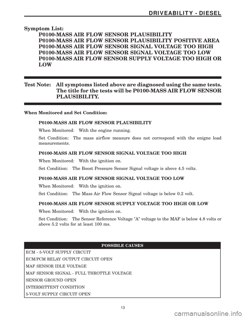
Symptom List:
P0100-MASS AIR FLOW SENSOR PLAUSIBILITY
P0100-MASS AIR FLOW SENSOR PLAUSIBILITY POSITIVE AREA
P0100-MASS AIR FLOW SENSOR SIGNAL VOLTAGE TOO HIGH
P0100-MASS AIR FLOW SENSOR SIGNAL VOLTAGE TOO LOW
P0100-MASS AIR FLOW SENSOR SUPPLY VOLTAGE TOO HIGH OR
LOW
Test Note: All symptoms listed above are diagnosed using the same tests.
The title for the tests will be P0100-MASS AIR FLOW SENSOR
PLAUSIBILITY.
When Monitored and Set Condition:
P0100-MASS AIR FLOW SENSOR PLAUSIBILITY
When Monitored: With the engine running.
Set Condition: The mass airflow measure does not correspond with the enigne load
measurements.
P0100-MASS AIR FLOW SENSOR SIGNAL VOLTAGE TOO HIGH
When Monitored: With the ignition on.
Set Condition: The Boost Pressure Sensor Signal voltage is above 4.5 volts.
P0100-MASS AIR FLOW SENSOR SIGNAL VOLTAGE TOO LOW
When Monitored: With the ignition on.
Set Condition: The Mass Air Flow Sensor Signal voltage is below 0.2 volt.
P0100-MASS AIR FLOW SENSOR SUPPLY VOLTAGE TOO HIGH OR LOW
When Monitored: With the ignition on.
Set Condition: The Sensor Reference Voltage9A9voltage to the MAF is below 4.8 volts or
above 5.2 volts for at least 100 ms.
POSSIBLE CAUSES
ECM - 5-VOLT SUPPLY CIRCUIT
ECM/PCM RELAY OUTPUT CIRCUIT OPEN
MAF SENSOR IDLE VOLTAGE
MAF SENSOR SIGNAL - FULL THROTTLE VOLTAGE
SENSOR GROUND OPEN
INTERMITTENT CONDITION
5-VOLT SUPPLY CIRCUIT OPEN
13
DRIVEABILITY - DIESEL
Page 1233 of 4284
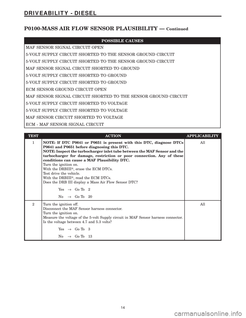
POSSIBLE CAUSES
MAF SENSOR SIGNAL CIRCUIT OPEN
5-VOLT SUPPLY CIRCUIT SHORTED TO THE SENSOR GROUND CIRCUIT
5-VOLT SUPPLY CIRCUIT SHORTED TO THE SENSOR GROUND CIRCUIT
MAF SENSOR SIGNAL CIRCUIT SHORTED TO GROUND
5-VOLT SUPPLY CIRCUIT SHORTED TO GROUND
5-VOLT SUPPLY CIRCUIT SHORTED TO GROUND
ECM SENSOR GROUND CIRCUIT OPEN
MAF SENSOR SIGNAL CIRCUIT SHORTED TO THE SENSOR GROUND CIRCUIT
5-VOLT SUPPLY CIRCUIT SHORTED TO VOLTAGE
5-VOLT SUPPLY CIRCUIT SHORTED TO VOLTAGE
MAF SENSOR CIRCUIT SHORTED TO VOLTAGE
ECM - MAF SENSOR SIGNAL CIRCUIT
TEST ACTION APPLICABILITY
1NOTE: If DTC P0641 or P0651 is present with this DTC, diagnose DTCs
P0641 and P0651 before diagnosing this DTC.
NOTE: Inspect the turbocharger inlet tube between the MAF Sensor and the
turbocharger for damage, restriction or poor connection. Any of these
conditions can cause a MAF Plausibility DTC.
Turn the ignition on.
With the DRBIIIt, erase the ECM DTCs.
Test drive the vehicle.
With the DRBIIIt, read the ECM DTCs.
Does the DRB III display a Mass Air Flow Sensor DTC?All
Ye s®Go To 2
No®Go To 20
2 Turn the ignition off.
Disconnect the MAF Sensor harness connector.
Turn the ignition on.
Measure the voltage of the 5-volt Supply circuit in MAF Sensor harness connector.
Is the voltage between 4.7 and 5.3 volts?All
Ye s®Go To 3
No®Go To 13
14
DRIVEABILITY - DIESEL
P0100-MASS AIR FLOW SENSOR PLAUSIBILITY ÐContinued
Page 1238 of 4284
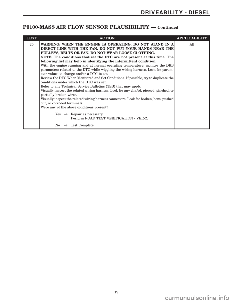
TEST ACTION APPLICABILITY
20WARNING: WHEN THE ENGINE IS OPERATING, DO NOT STAND IN A
DIRECT LINE WITH THE FAN. DO NOT PUT YOUR HANDS NEAR THE
PULLEYS, BELTS OR FAN. DO NOT WEAR LOOSE CLOTHING.
NOTE: The conditions that set the DTC are not present at this time. The
following list may help in identifying the intermittent condition.
With the engine running and at normal operating temperature, monitor the DRB
parameters related to the DTC while wiggling the wiring harness. Look for param-
eter values to change and/or a DTC to set.
Review the DTC When Monitored and Set Conditions. If possible, try to duplicate the
conditions under which the DTC was set.
Refer to any Technical Service Bulletins (TSB) that may apply.
Visually inspect the related wiring harness. Look for any chafed, pierced, pinched, or
partially broken wires.
Visually inspect the related wiring harness connectors. Look for broken, bent, pushed
out, or corroded terminals.
Were any of the above conditions present?All
Ye s®Repair as necessary.
Perform ROAD TEST VERIFICATION - VER-2.
No®Test Complete.
19
DRIVEABILITY - DIESEL
P0100-MASS AIR FLOW SENSOR PLAUSIBILITY ÐContinued
Page 1242 of 4284
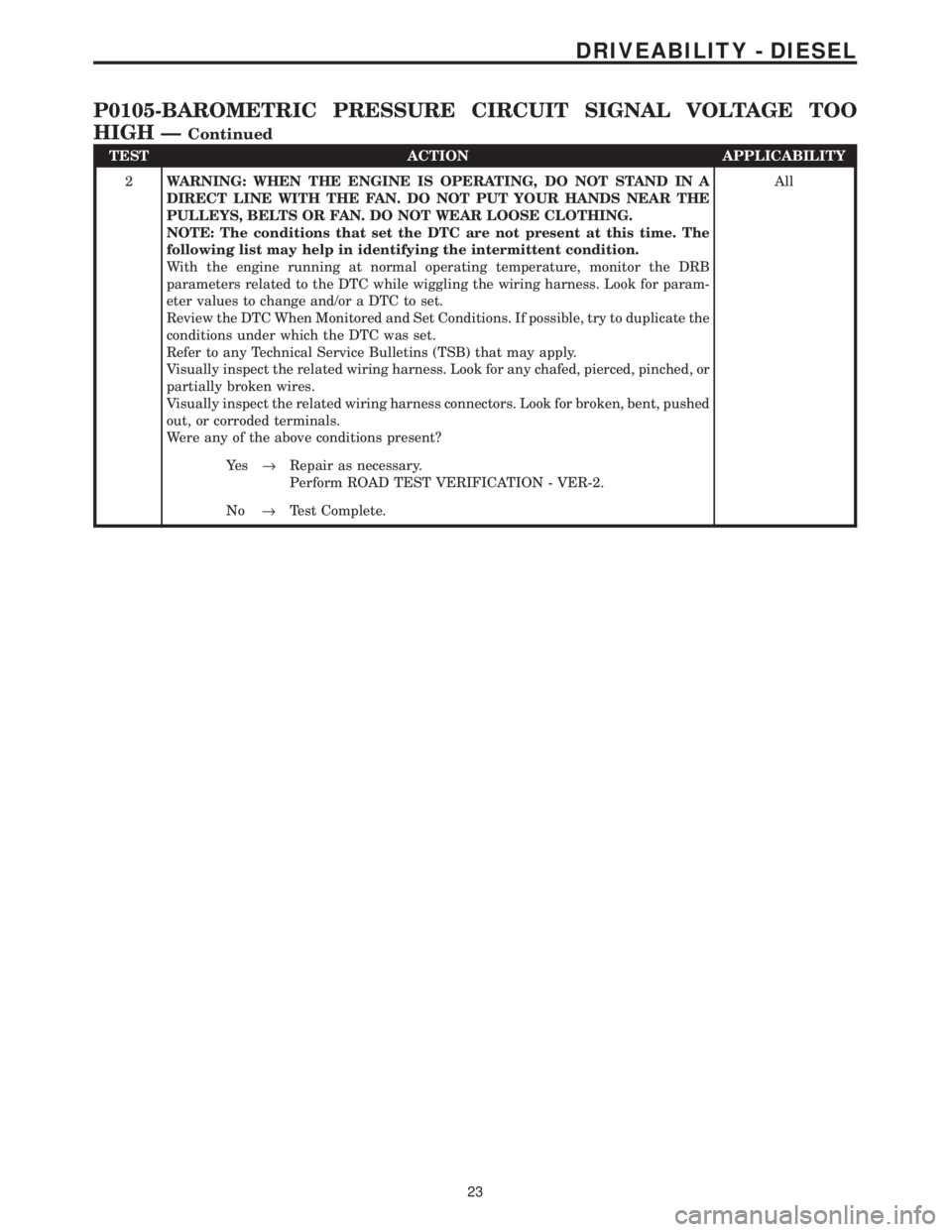
TEST ACTION APPLICABILITY
2WARNING: WHEN THE ENGINE IS OPERATING, DO NOT STAND IN A
DIRECT LINE WITH THE FAN. DO NOT PUT YOUR HANDS NEAR THE
PULLEYS, BELTS OR FAN. DO NOT WEAR LOOSE CLOTHING.
NOTE: The conditions that set the DTC are not present at this time. The
following list may help in identifying the intermittent condition.
With the engine running at normal operating temperature, monitor the DRB
parameters related to the DTC while wiggling the wiring harness. Look for param-
eter values to change and/or a DTC to set.
Review the DTC When Monitored and Set Conditions. If possible, try to duplicate the
conditions under which the DTC was set.
Refer to any Technical Service Bulletins (TSB) that may apply.
Visually inspect the related wiring harness. Look for any chafed, pierced, pinched, or
partially broken wires.
Visually inspect the related wiring harness connectors. Look for broken, bent, pushed
out, or corroded terminals.
Were any of the above conditions present?All
Ye s®Repair as necessary.
Perform ROAD TEST VERIFICATION - VER-2.
No®Test Complete.
23
DRIVEABILITY - DIESEL
P0105-BAROMETRIC PRESSURE CIRCUIT SIGNAL VOLTAGE TOO
HIGH Ð
Continued