2001 CHRYSLER VOYAGER washer fluid
[x] Cancel search: washer fluidPage 1582 of 4284
(7) Install steering knuckle in clevis bracket of
strut damper assembly. Install the strut damper to
steering knuckle attaching bolts. Tighten both bolts
to a torque of 81 N´m (60 ft. lbs.) plus an additional
1/4 turn.
(8) Install tie rod end into steering knuckle. Start
attaching nut onto stud of tie rod end. While holding
stud of tie rod end stationary using a socket, (Fig. 6)
tighten tie rod end to steering knuckle attaching nut.
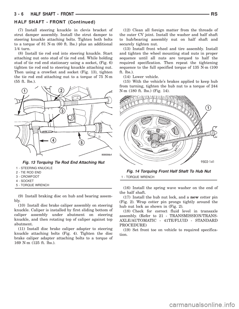
Then using a crowfoot and socket (Fig. 13), tighten
the tie rod end attaching nut to a torque of 75 N´m
(55 ft. lbs.).
(9) Install braking disc on hub and bearing assem-
bly.
(10) Install disc brake caliper assembly on steering
knuckle. Caliper is installed by first sliding bottom of
caliper assembly under abutment on steering
knuckle, and then rotating top of caliper against top
abutment.
(11) Install disc brake caliper adapter to steering
knuckle attaching bolts (Fig. 4). Tighten the disc
brake caliper adapter attaching bolts to a torque of
169 N´m (125 ft. lbs.).(12) Clean all foreign matter from the threads of
the outer CV joint. Install the washer and half shaft
to hub/bearing assembly nut on half shaft and
securely tighten nut.
(13) Install front wheel and tire assembly. Install
and tighten the wheel mounting stud nuts in proper
sequence until all nuts are torqued to half the
required specification. Then repeat the tightening
sequence to the full specified torque of 135 N´m (100
ft. lbs.).
(14) Lower vehicle.
(15) With the vehicle's brakes applied to keep hub
from turning, tighten the hub nut to a torque of 244
N´m (180 ft. lbs.) (Fig. 14).
(16) Install the spring wave washer on the end of
the half shaft.
(17) Install the hub nut lock, and anewcotter pin
(Fig. 2). Wrap cotter pin prongs tightly around the
hub nut lock as shown in (Fig. 2).
(18) Check for correct fluid level in transaxle
assembly. (Refer to 21 - TRANSMISSION/TRANS-
AXLE/AUTOMATIC - 41TE/FLUID - STANDARD
PROCEDURE)
(19) Set front toe on vehicle to required specifica-
tion.
Fig. 13 Torquing Tie Rod End Attaching Nut
1 - STEERING KNUCKLE
2 - TIE ROD END
3 - CROWFOOT
4 - SOCKET
5 - TORQUE WRENCHFig. 14 Torquing Front Half Shaft To Hub Nut
1 - TORQUE WRENCH
3 - 6 HALF SHAFT - FRONTRS
HALF SHAFT - FRONT (Continued)
Page 1603 of 4284
adjustment, maintenance or fluid checks required
during the life of the unit.
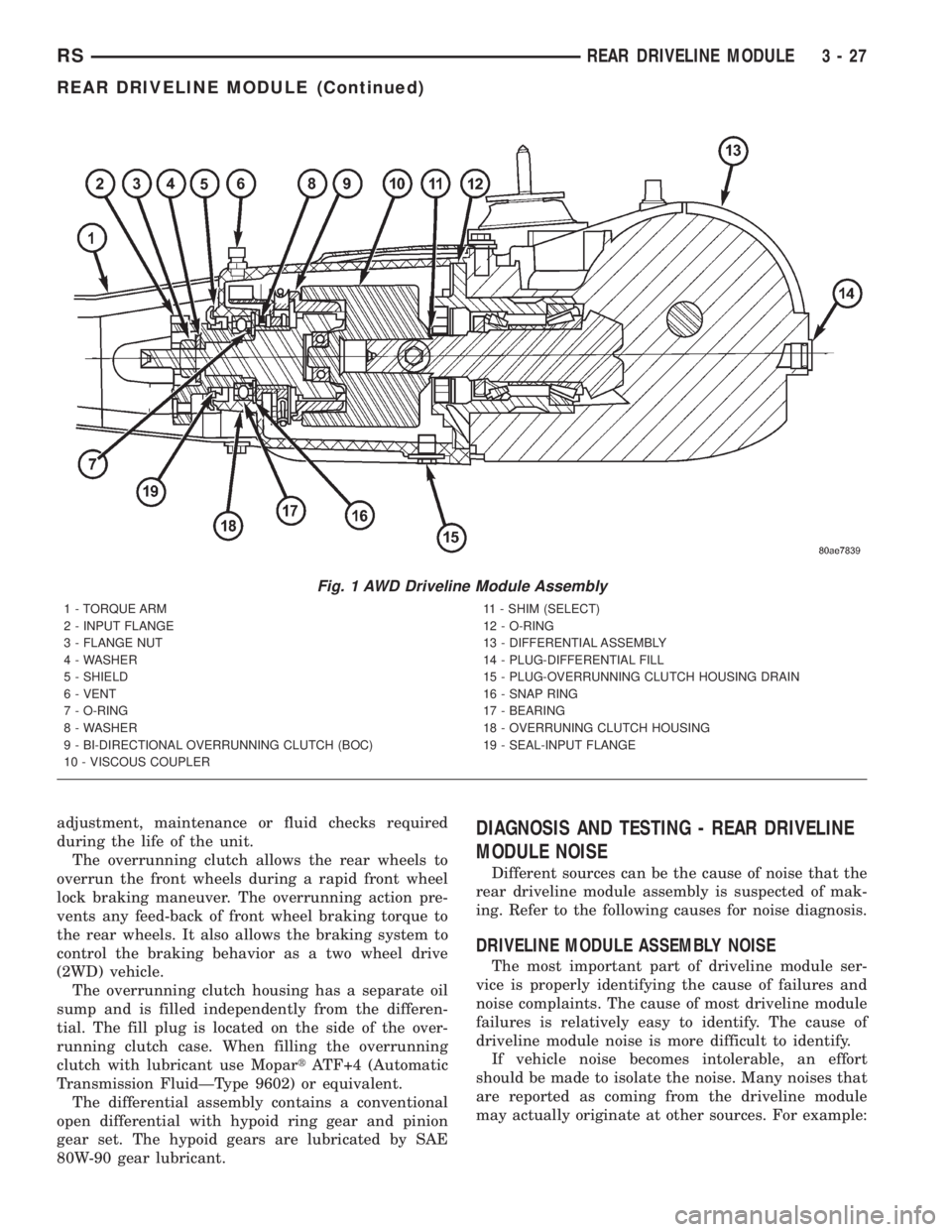
The overrunning clutch allows the rear wheels to
overrun the front wheels during a rapid front wheel
lock braking maneuver. The overrunning action pre-
vents any feed-back of front wheel braking torque to
the rear wheels. It also allows the braking system to
control the braking behavior as a two wheel drive
(2WD) vehicle.
The overrunning clutch housing has a separate oil
sump and is filled independently from the differen-
tial. The fill plug is located on the side of the over-
running clutch case. When filling the overrunning
clutch with lubricant use MopartATF+4 (Automatic
Transmission FluidÐType 9602) or equivalent.
The differential assembly contains a conventional
open differential with hypoid ring gear and pinion
gear set. The hypoid gears are lubricated by SAE
80W-90 gear lubricant.DIAGNOSIS AND TESTING - REAR DRIVELINE
MODULE NOISE
Different sources can be the cause of noise that the
rear driveline module assembly is suspected of mak-
ing. Refer to the following causes for noise diagnosis.
DRIVELINE MODULE ASSEMBLY NOISE
The most important part of driveline module ser-
vice is properly identifying the cause of failures and
noise complaints. The cause of most driveline module
failures is relatively easy to identify. The cause of
driveline module noise is more difficult to identify.
If vehicle noise becomes intolerable, an effort
should be made to isolate the noise. Many noises that
are reported as coming from the driveline module
may actually originate at other sources. For example:
Fig. 1 AWD Driveline Module Assembly
1 - TORQUE ARM
2 - INPUT FLANGE
3 - FLANGE NUT
4 - WASHER
5 - SHIELD
6 - VENT
7 - O-RING
8 - WASHER
9 - BI-DIRECTIONAL OVERRUNNING CLUTCH (BOC)
10 - VISCOUS COUPLER11 - SHIM (SELECT)
12 - O-RING
13 - DIFFERENTIAL ASSEMBLY
14 - PLUG-DIFFERENTIAL FILL
15 - PLUG-OVERRUNNING CLUTCH HOUSING DRAIN
16 - SNAP RING
17 - BEARING
18 - OVERRUNING CLUTCH HOUSING
19 - SEAL-INPUT FLANGE
RSREAR DRIVELINE MODULE3-27
REAR DRIVELINE MODULE (Continued)
Page 1605 of 4284
DIAGNOSIS AND TESTING - REAR DRIVELINE
MODULE OPERATION
Driveline module operation requires relatively
straight-forward diagnosis. Refer to the following
chart:
DRIVELINE MODULE DIAGNOSIS CHART
CONDITION POSSIBLE CAUSES CORRECTION
Rear wheels not
overrunning1) Bi-directional overrunning clutch
failure1) Replace overrunning clutch
components as required
No AWD in forward or
reverse directions, propeller
shaft turning1) Bi-directional overrunning clutch
failure1) Replace overrunning clutch
components as required
2) Viscous coupling failure 2) Replace viscous coupling
3) Rear differential failure 3) Replace the rear differential
assembly
No AWD in forward or
reverse directions, propeller
shaft not turning1) Power transfer unit failure. 1) Replace power transfer unit
components as necessary
Vibration at all speeds,
continuous torque transfer1) Mis-matched tires, worn tires on
front axle.1) Replace worn or incorrect
(mis-matched) tires with same
make and size
REMOVAL
(1) Raise vehicle on hoist.
(2) Drain fluid from overrunning clutch housing
and/or differential assembly if necessary.
(3) Remove propeller shaft. (Refer to 3 - DIFFER-
ENTIAL & DRIVELINE/PROPELLER SHAFT -
REMOVAL)
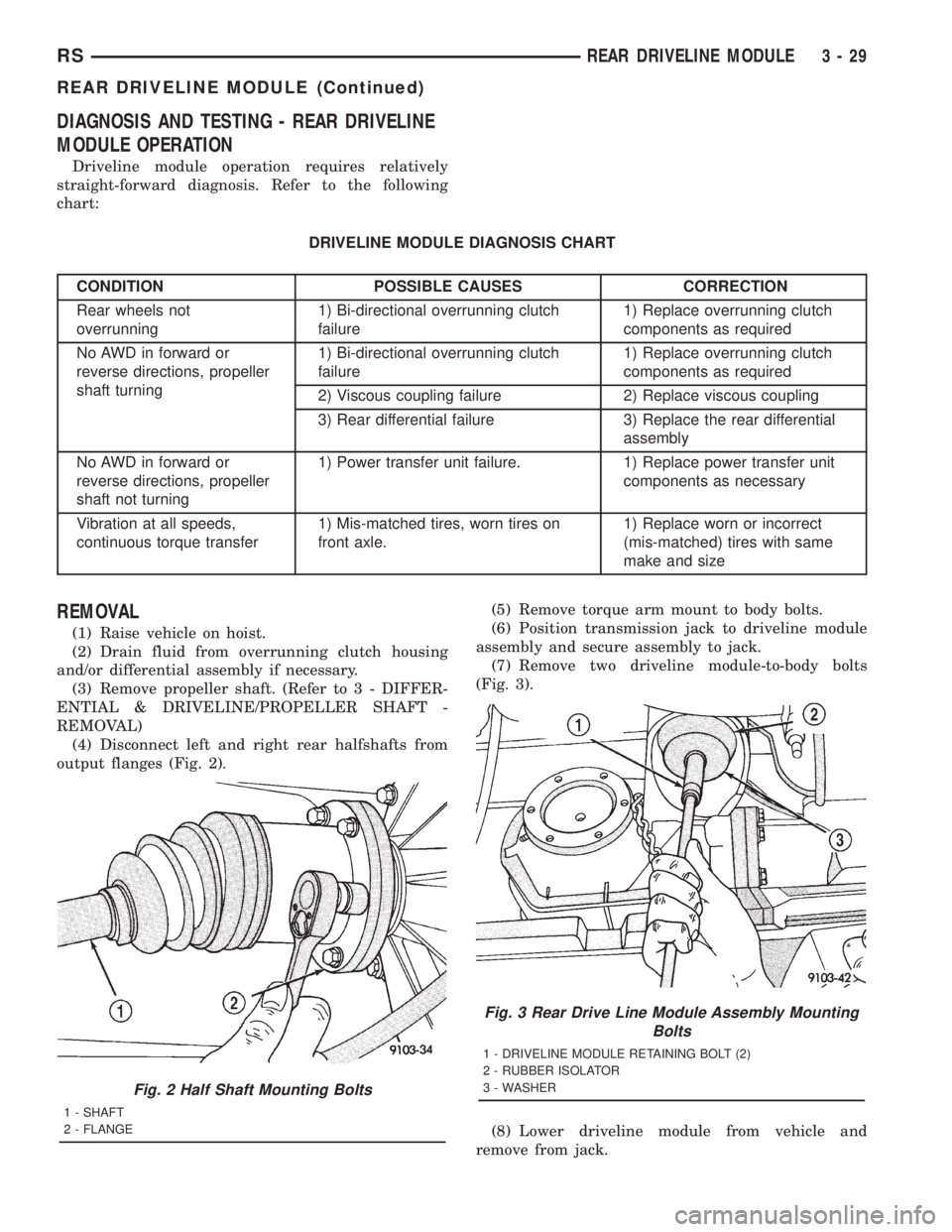
(4) Disconnect left and right rear halfshafts from
output flanges (Fig. 2).(5) Remove torque arm mount to body bolts.
(6) Position transmission jack to driveline module
assembly and secure assembly to jack.
(7) Remove two driveline module-to-body bolts
(Fig. 3).
(8) Lower driveline module from vehicle and
remove from jack.
Fig. 2 Half Shaft Mounting Bolts
1 - SHAFT
2 - FLANGE
Fig. 3 Rear Drive Line Module Assembly Mounting
Bolts
1 - DRIVELINE MODULE RETAINING BOLT (2)
2 - RUBBER ISOLATOR
3 - WASHER
RSREAR DRIVELINE MODULE3-29
REAR DRIVELINE MODULE (Continued)
Page 1623 of 4284
When a high speed difference (shear) occurs
because of loss of traction (one axle spinning faster
than the other), the silicone fluid expands as it heats
from this shearing. When the silicone expands to fill
the viscous coupler completely, this pressure differ-
ence is high enough to squeeze each pair of plates
together. The resulting hump torque is up to 8 times
higher than the shear torque. When the viscous cou-
pler is in the hump mode, it does not lock the axles
(undifferentiated 4-Wheel Drive). It controls the
amount of slippage while delivering maximum power
to the axle having greatest traction. Once the speed
difference equalizes the fluid and plates cool down
and the viscous coupler goes back to the shear mode.
TORQUE ARM
REMOVAL
(1) Raise vehicle on hoist.
(2) Remove rear driveline module assembly. (Refer
to 3 - DIFFERENTIAL & DRIVELINE/REAR DRIV-
ELINE MODULE - REMOVAL)
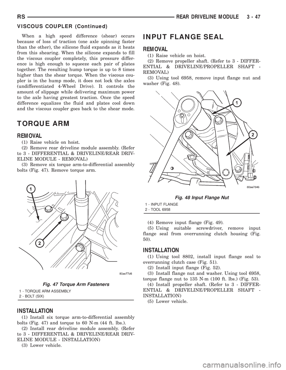
(3) Remove six torque arm-to-differential assembly
bolts (Fig. 47). Remove torque arm.
INSTALLATION
(1) Install six torque arm-to-differential assembly
bolts (Fig. 47) and torque to 60 N´m (44 ft. lbs.).
(2) Install rear driveline module assembly. (Refer
to 3 - DIFFERENTIAL & DRIVELINE/REAR DRIV-
ELINE MODULE - INSTALLATION)
(3) Lower vehicle.
INPUT FLANGE SEAL
REMOVAL
(1) Raise vehicle on hoist.
(2) Remove propeller shaft. (Refer to 3 - DIFFER-
ENTIAL & DRIVELINE/PROPELLER SHAFT -
REMOVAL)
(3) Using tool 6958, remove input flange nut and
washer (Fig. 48).
(4) Remove input flange (Fig. 49).
(5) Using suitable screwdriver, remove input
flange seal from overrunning clutch housing (Fig.
50).
INSTALLATION
(1) Using tool 8802, install input flange seal to
overrunning clutch case (Fig. 51).
(2) Install input flange (Fig. 52).
(3) Install flange nut and washer. Using tool 6958,
torque flange nut to 135 N´m (100 ft. lbs.) (Fig. 53).
(4) Install propeller shaft. (Refer to 3 - DIFFER-
ENTIAL & DRIVELINE/PROPELLER SHAFT -
INSTALLATION)
(5) Lower vehicle.
Fig. 47 Torque Arm Fasteners
1 - TORQUE ARM ASSEMBLY
2 - BOLT (SIX)
Fig. 48 Input Flange Nut
1 - INPUT FLANGE
2 - TOOL 6958
RSREAR DRIVELINE MODULE3-47
VISCOUS COUPLER (Continued)
Page 1648 of 4284
(20) Road test vehicle. The automatic adjuster will
continue the brake adjustment during the road test
of the vehicle.
ADJUSTMENT - REAR DRUM BRAKE SHOES
NOTE: Normally, self-adjusting drum brakes do not
require manual brake shoe adjustment. Although, in
the event of a brake shoe replacement, it is advis-
able to make the initial adjustment manually to
speed up the adjusting time.
NOTE: Before raising the vehicle, verify the parking
brake lever is fully released.
(1) Raise the vehicle. (Refer to LUBRICATION &
MAINTENANCE/HOISTING - STANDARD PROCE-
DURE).
(2) Remove rubber plug from rear brake adjusting
hole in the rear brake support plate.
(3) Insert a thin screwdriver through the adjusting
hole in the support plate and against the star wheel
of the adjusting screw. Move handle of the tool
upward rotating the star wheel until a slight drag is
felt when tire and wheel assembly is rotated.
(4) Insert a second thin screwdriver or piece of
welding rod into brake adjusting hole and push the
adjusting lever out of engagement with the star
wheel.Care should be taken so as not to bend
adjusting lever or distort lever spring.
(5) While holding the adjusting lever out of
engagement, back off the star wheel just enough to
ensure a free wheel with no brake shoe drag.
(6) Repeat the above adjustment at the other rear
wheel.
(7) Install the adjusting hole rubber plugs back in
the rear brake support plates.
(8) Lower the vehicle.
DISC BRAKE CALIPERS -
FRONT
REMOVAL - FRONT DISC BRAKE CALIPER
(DISC/DISC BRAKES)
(1) Depress the brake pedal past its first inch of
travel and hold it in this position using a brake pedal
depressor (holding) tool. This is done to isolate the
master cylinder from the brake hydraulic system dis-
allowing the brake fluid to completely drain out of
the brake fluid reservoir.
(2) Raise the vehicle. (Refer to LUBRICATION &
MAINTENANCE/HOISTING - STANDARD PROCE-
DURE).
(3) Remove front wheel and tire assembly.(4) Remove the banjo bolt connecting the brake
hose to the brake caliper. There are two washers (one
on each side of the brake hose fitting) that will come
off with the banjo bolt. Discard these washers.
(5) Remove the 2 caliper guide pin bolts.
(6) Remove the brake caliper from the adapter.
REMOVAL - FRONT DISC BRAKE CALIPER
(DISC/DRUM BRAKES)
(1) Using a brake pedal holding tool, depress the
brake pedal past its first one inch of travel and hold
it in this position. This will isolate the master cylin-
der from the brake hydraulic system and will not
allow the brake fluid to drain out of the master cyl-
inder reservoir when the lines are opened.
(2) Raise the vehicle. Refer to HOISTING in
LUBRICATION AND MAINTENANCE.
(3) Remove the front tire and wheel assembly.
(4) Remove the banjo bolt connecting the brake
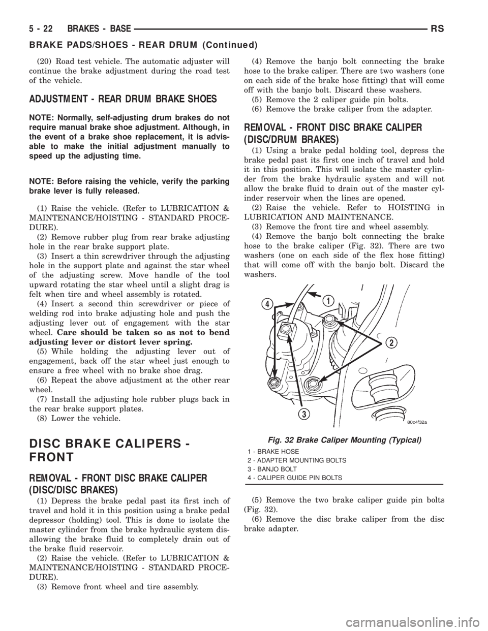
hose to the brake caliper (Fig. 32). There are two
washers (one on each side of the flex hose fitting)
that will come off with the banjo bolt. Discard the
washers.
(5) Remove the two brake caliper guide pin bolts
(Fig. 32).
(6) Remove the disc brake caliper from the disc
brake adapter.
Fig. 32 Brake Caliper Mounting (Typical)
1 - BRAKE HOSE
2 - ADAPTER MOUNTING BOLTS
3 - BANJO BOLT
4 - CALIPER GUIDE PIN BOLTS
5 - 22 BRAKES - BASERS
BRAKE PADS/SHOES - REAR DRUM (Continued)
Page 1652 of 4284
(10) Road test the vehicle and make several stops
to wear off any foreign material on the brakes and to
seat the brake shoe linings.
INSTALLATION - FRONT DISC BRAKE CALIPER
(DISC/DRUM BRAKES)
CAUTION: TRW and Continental Teves brake cali-
pers are not interchangeable. Each caliper is specif-
ically designed for the unique brake system (TRW -
disc/drum brake combination and Continental Teves
- disc/disc brake combination). If calipers are inter-
changed, improper performance, noise and
increased stopping distance can occur.
(1) Completely retract the caliper piston back into
the bore of the caliper. Use a C-clamp to retract the
piston if necessary. Place a wood block over the pis-
ton before installing the C-clamp to avoid damaging
the piston.
CAUTION: Use care when installing the caliper onto
the disc brake adapter to avoid damaging the boots
on the caliper guide pins.
(2) Install the disc brake caliper over the brake
shoes on the brake caliper adapter.
(3) Align the caliper guide pin bolt holes with the
guide pins. Install the caliper guide pin bolts and
tighten them to a torque of 35 N´m (26 ft. lbs.) (Fig.
32).
(4) Install the banjo bolt connecting the brake hose
to the brake caliper (Fig. 32). Install NEW copper
washers on each side of the hose fitting as the banjo
bolt is guided through the fitting. Thread the banjo
bolt into the caliper and tighten it to a torque of 47
N´m (35 ft. lbs.).
(5) Install the tire and wheel assembly. Tighten
the wheel mounting nuts to a torque of 135 N´m (100
ft. lbs.).
(6) Lower the vehicle.
(7) Remove the brake pedal holding tool.
(8) Bleed the caliper as necessary. (Refer to 5 -
BRAKES - BASE - STANDARD PROCEDURE).
(9) Road test the vehicle and make several stops to
wear off any foreign material on the brakes and to
seat the brake shoes.
DISC BRAKE CALIPERS -
REAR
REMOVAL - REAR DISC BRAKE CALIPER
NOTE: Handling of the rotor and caliper, must be
done in such a way as to avoid damage to the rotorand scratching or nicking of lining on the brake
shoes.
(1) Depress the brake pedal past its first inch of
travel and hold it in this position using a brake pedal
depressor (holding) tool. This is done to isolate the
master cylinder from the brake hydraulic system dis-
allowing the brake fluid to completely drain out of
the brake fluid reservoir.
(2) Raise the vehicle. (Refer to LUBRICATION &
MAINTENANCE/HOISTING - STANDARD PROCE-
DURE)
(3) Remove rear wheel and tire assembly from
vehicle.
(4) Remove the banjo bolt connecting the brake
hose to the brake caliper. There are two washers (one
on each side of the brake hose fitting) that will come
off with the banjo bolt. Discard these washers.
(5) Remove the disc brake caliper to adapter guide
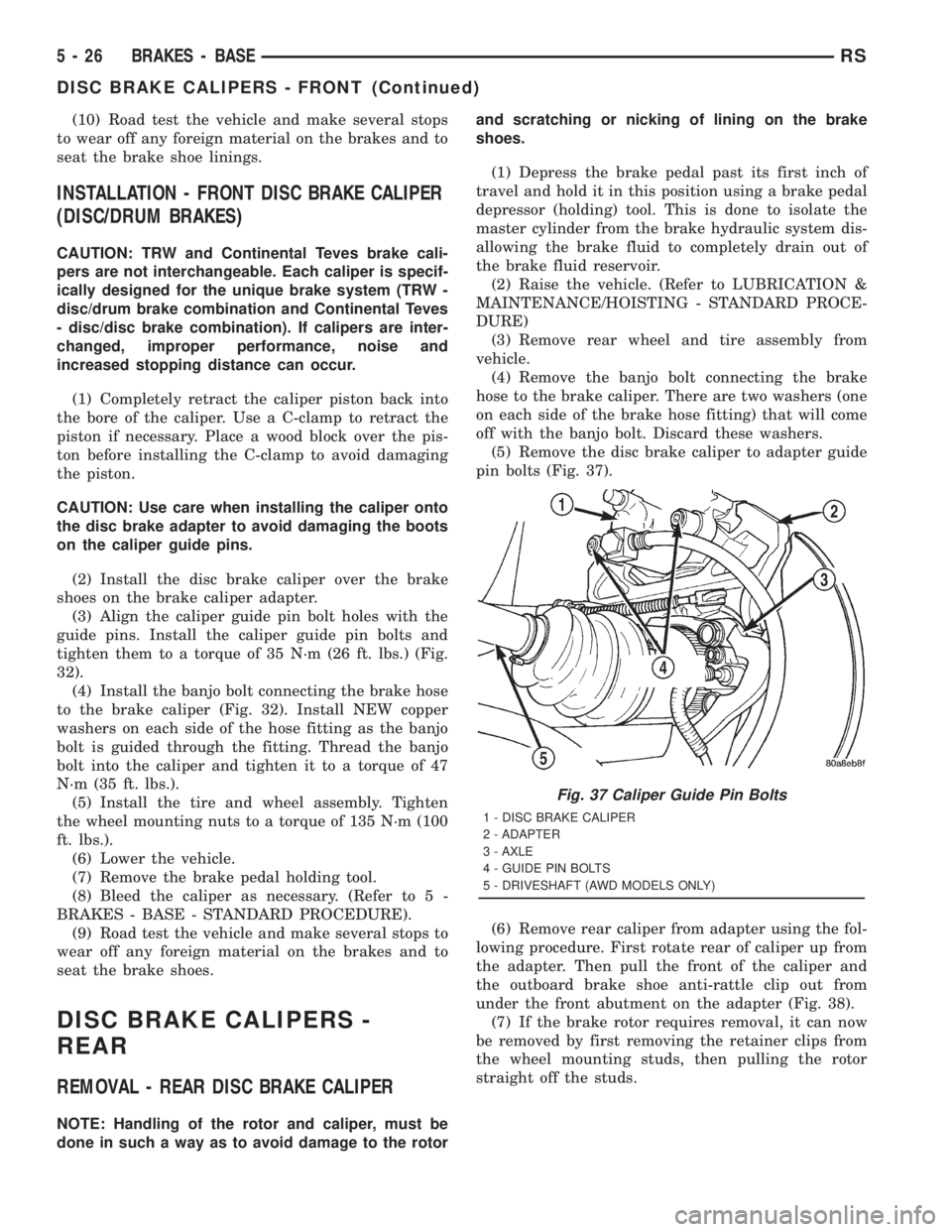
pin bolts (Fig. 37).
(6) Remove rear caliper from adapter using the fol-
lowing procedure. First rotate rear of caliper up from
the adapter. Then pull the front of the caliper and
the outboard brake shoe anti-rattle clip out from
under the front abutment on the adapter (Fig. 38).
(7) If the brake rotor requires removal, it can now
be removed by first removing the retainer clips from
the wheel mounting studs, then pulling the rotor
straight off the studs.
Fig. 37 Caliper Guide Pin Bolts
1 - DISC BRAKE CALIPER
2 - ADAPTER
3 - AXLE
4 - GUIDE PIN BOLTS
5 - DRIVESHAFT (AWD MODELS ONLY)
5 - 26 BRAKES - BASERS
DISC BRAKE CALIPERS - FRONT (Continued)
Page 1664 of 4284
DIAGNOSIS AND TESTING - POWER BRAKE
BOOSTER
BASIC TEST
(1) With engine off, depress and release the brake
pedal several times to purge all vacuum from the
power brake booster.
(2) Depress and hold the pedal with light effort (15
to 25 lbs. pressure), then start the engine.
The pedal should fall slightly, then hold. Less effort
should be needed to apply the pedal at this time. If
the pedal fell as indicated, perform the VACUUM
LEAK TEST listed after the BASIC TEST. If the
pedal did not fall, continue on with this BASIC TEST.
(3) Disconnect the vacuum hose on the vacuum
check valve, then place a vacuum gauge in line
between the vacuum hose and the valve.
(4) Start the engine.
(5) When the engine is at warm operating temper-
ature, allow it to idle and check the vacuum at the
gauge.
If the vacuum supply is 12 inches Hg (40.5 kPa) or
more, the power brake booster is defective and must
be replaced. If the vacuum supply is below 12 inches
Hg, continue on with this BASIC TEST.
(6) Shut off the engine.
(7) Connect the vacuum gauge to the vacuum ref-
erence port on the engine intake manifold.
(8) Start the engine and observe the vacuum
gauge.
If the vacuum is still low, check the engine tune
and repair as necessary. If the vacuum is above 12
inches Hg, the hose or check valve to the booster has
a restriction or leak.
Once an adequate vacuum supply is obtained,
repeat the BASIC TEST.
VACUUM LEAK TEST
(1) Disconnect the vacuum hose on the vacuum
check valve, then place a vacuum gauge in line
between the vacuum hose and the valve.
(2) Start the engine.
(3) Allow the engine to warm up to normal operat-
ing temperature and engine idle.
(4) Using vacuum line pliers, close off the vacuum
supply hose near the booster, but before the vacuum
gauge, then observe the vacuum gauge.
If the vacuum drop exceeds 1.0 inch Hg (3.3 kPa)
in one minute, repeat the above steps to confirm the
reading. The vacuum loss should be less than 1.0
inch Hg in one minute time span. If the loss is more
than 1.0 inch Hg, replace the power brake booster. If
it is not, continue on with this test.
(5) Remove the pliers from the hose temporarily.
(6) Apply light effort (approximately 15 lbs. of
force) to the brake pedal and hold the pedal steady.Do not move the pedal once the pressure is applied
or the test results may vary.
(7) Have an assistant reattach the vacuum line
pliers to the vacuum supply hose.
(8) Allow 5 seconds for stabilization, then observe
the vacuum gauge.
If the vacuum drop exceeds 3.0 inches Hg (10 kPa)
in 15 seconds, repeat the above steps to confirm the
reading. The vacuum loss should be less than 3.0
inches Hg in 15 seconds time span. If the loss is
more than 3.0 inches Hg, replace the power brake
booster. If it is not, the booster is not defective.
(9) Remove the pliers and vacuum gauge.
REMOVAL - POWER BRAKE BOOSTER
CAUTION: Reserve vacuum in power brake booster
must be pumped down (removed) before removing
master cylinder from booster. This is necessary to
prevent booster from sucking in any contamination
as master cylinder is removed. This can be done
simply by pumping the brake pedal, with the vehi-
cle's engine not running, until a firm feeling brake
pedal is achieved.
(1) With engine not running, pump the brake
pedal until a firm pedal is achieved (4-5 strokes).
(2) Remove negative battery cable terminal from
battery.
(3) Remove positive battery cable terminal from
battery.
(4) Remove battery thermal guard shield.
(5) Remove battery clamp, nut and battery from
the battery tray.
(6) Remove screw securing engine coolant filler
tube to battery tray.
(7) If the vehicle is equipped with speed control,
disconnect the vacuum hose at the vacuum tank built
into the battery tray.
(8) Remove the two nuts and one bolt securing bat-
tery tray in place. Remove battery tray.
(9) If vehicle is equipped with speed control:
(a) Disconnect wiring harness connector from
the speed control servo.
(b) Remove the two servo mounting nuts.
(c) Lay speed control servo off to the side, out of
the way.
(10) Remove the wiper module (unit). (Refer to 8 -
ELECTRICAL/WIPERS/WASHERS/WIPER MOD-
ULE - REMOVAL)
(11) Disconnect wiring harness connector from
brake fluid level switch in master cylinder fluid res-
ervoir (Fig. 54).
5 - 38 BRAKES - BASERS
POWER BRAKE BOOSTER (Continued)
Page 1667 of 4284
CAUTION: The master cylinder (and its rear seal) is
used to create the seal for holding vacuum in the
vacuum booster. The vacuum seal on the master
cylinder MUST be replaced with a NEW seal when-
ever the master cylinder is removed from the vac-
uum booster.
CAUTION: When removing the vacuum seal from
the master cylinder do not use a sharp tool.
(8) Using a soft tool such as a trim stick, remove
the vacuum seal from the master cylinder mounting
flange.
(9) Install a NEW vacuum seal on rear mounting
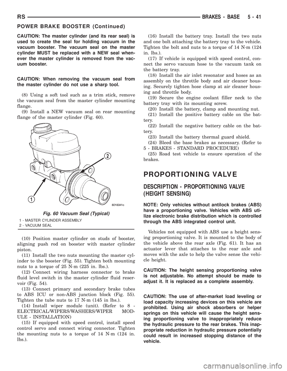
flange of the master cylinder (Fig. 60).
(10) Position master cylinder on studs of booster,
aligning push rod on booster with master cylinder
piston.
(11) Install the two nuts mounting the master cyl-
inder to the booster (Fig. 55). Tighten both mounting
nuts to a torque of 25 N´m (225 in. lbs.).
(12) Connect wiring harness connector to brake
fluid level switch in the master cylinder fluid reser-
voir (Fig. 54).
(13) Connect primary and secondary brake tubes
to ABS ICU or non-ABS junction block (Fig. 55).
Tighten the tube nuts to 17 N´m (145 in lbs.).
(14) Install wiper module (unit). (Refer to 8 -
ELECTRICAL/WIPERS/WASHERS/WIPER MOD-
ULE - INSTALLATION)
(15) If equipped with speed control, install speed
control servo and connect wiring connector. Tighten
the mounting nuts to a torque of 14 N´m (124 in.
lbs.).(16) Install the battery tray. Install the two nuts
and one bolt attaching the battery tray to the vehicle.
Tighten the bolt and nuts to a torque of 14 N´m (124
in. lbs.).
(17) If vehicle is equipped with speed control, con-
nect the servo vacuum hose to the vacuum tank on
the battery tray.
(18) Install the air inlet resonator and hoses as an
assembly on the throttle body and air cleaner hous-
ing. Securely tighten hose clamp at air cleaner hous-
ing and throttle body.
(19) Secure the engine coolant filler neck to the
battery tray with its mounting screw.
(20) Install the battery, clamp and mounting nut.
(21) Install the positive battery cable on the bat-
tery.
(22) Install the negative battery cable on the bat-
tery.
(23) Install the battery thermal guard shield.
(24) Bleed the base brakes as necessary. (Refer to
5 - BRAKES - STANDARD PROCEDURE)
(25) Road test vehicle to ensure operation of the
brakes.
PROPORTIONING VALVE
DESCRIPTION - PROPORTIONING VALVE
(HEIGHT SENSING)
NOTE: Only vehicles without antilock brakes (ABS)
have a proportioning valve. Vehicles with ABS uti-
lize electronic brake distribution which is controlled
through the ABS integrated control unit.
Vehicles not equipped with ABS use a height sens-
ing proportioning valve. It is mounted to the body of
the vehicle above the rear axle (Fig. 61). It has an
actuator lever that attaches to the rear axle and
moves with the axle to help the valve sense the vehi-
cle height.
CAUTION: The height sensing proportioning valve
is not adjustable. No attempt should be made to
adjust it. It is replaced as a complete assembly.
CAUTION: The use of after-market load leveling or
load capacity increasing devices on this vehicle are
prohibited. Using air shock absorbers or helper
springs on this vehicle will cause the height sens-
ing proportioning valve to inappropriately reduce
the hydraulic pressure to the rear brakes. This inap-
propriate reduction in hydraulic pressure potentially
could result in increased stopping distance of the
vehicle.
Fig. 60 Vacuum Seal (Typical)
1 - MASTER CYLINDER ASSEMBLY
2 - VACUUM SEAL
RSBRAKES - BASE5-41
POWER BRAKE BOOSTER (Continued)