2001 CHRYSLER VOYAGER washer fluid
[x] Cancel search: washer fluidPage 2269 of 4284
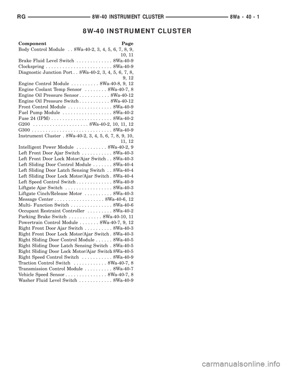
8W-40 INSTRUMENT CLUSTER
Component Page
Body Control Module . . 8Wa-40-2, 3, 4, 5, 6, 7, 8, 9,
10, 11
Brake Fluid Level Switch............. 8Wa-40-9
Clockspring........................ 8Wa-40-9
Diagnostic Junction Port . . 8Wa-40-2, 3, 4, 5, 6, 7, 8,
9, 12
Engine Control Module.......... 8Wa-40-8, 9, 12
Engine Coolant Temp Sensor........ 8Wa-40-7, 8
Engine Oil Pressure Sensor........... 8Wa-40-12
Engine Oil Pressure Switch........... 8Wa-40-12
Front Control Module................ 8Wa-40-9
Fuel Pump Module.................. 8Wa-40-2
Fuse 24 (IPM)...................... 8Wa-40-2
G200.................... 8Wa-40-2, 10, 11, 12
G300............................. 8Wa-40-9
Instrument Cluster . 8Wa-40-2, 3, 4, 5, 6, 7, 8, 9, 10,
11 , 1 2
Intelligent Power Module........... 8Wa-40-2, 9
Left Front Door Ajar Switch........... 8Wa-40-3
Left Front Door Lock Motor/Ajar Switch . . 8Wa-40-3
Left Sliding Door Control Module....... 8Wa-40-4
Left Sliding Door Latch Sensing Switch . . 8Wa-40-4
Left Sliding Door Lock Motor/Ajar Switch . 8Wa-40-4
Left Speed Control Switch............. 8Wa-40-9
Liftgate Ajar Switch................. 8Wa-40-3
Liftgate Cinch/Release Motor.......... 8Wa-40-3
Message Center.................. 8Wa-40-6, 12
Multi- Function Switch............... 8Wa-40-6
Occupant Restraint Controller......... 8Wa-40-2
Parking Brake Switch............ 8Wa-40-10, 11
Powertrain Control Module....... 8Wa-40-7, 9, 12
Right Front Door Ajar Switch.......... 8Wa-40-3
Right Front Door Lock Motor/Ajar Switch . 8Wa-40-3
Right Sliding Door Control Module...... 8Wa-40-5
Right Sliding Door Latch Sensing Switch . 8Wa-40-5
Right Sliding Door Lock Motor/Ajar Switch. 8Wa-40-5
Right Speed Control Switch........... 8Wa-40-9
Traction Control Switch............ 8Wa-40-7, 8
Transmission Control Module.......... 8Wa-40-7
Vehicle Speed Sensor............... 8Wa-40-7, 8
Washer Fluid Level Switch............ 8Wa-40-9
RG8W-40 INSTRUMENT CLUSTER8Wa-40-1
Page 2381 of 4284
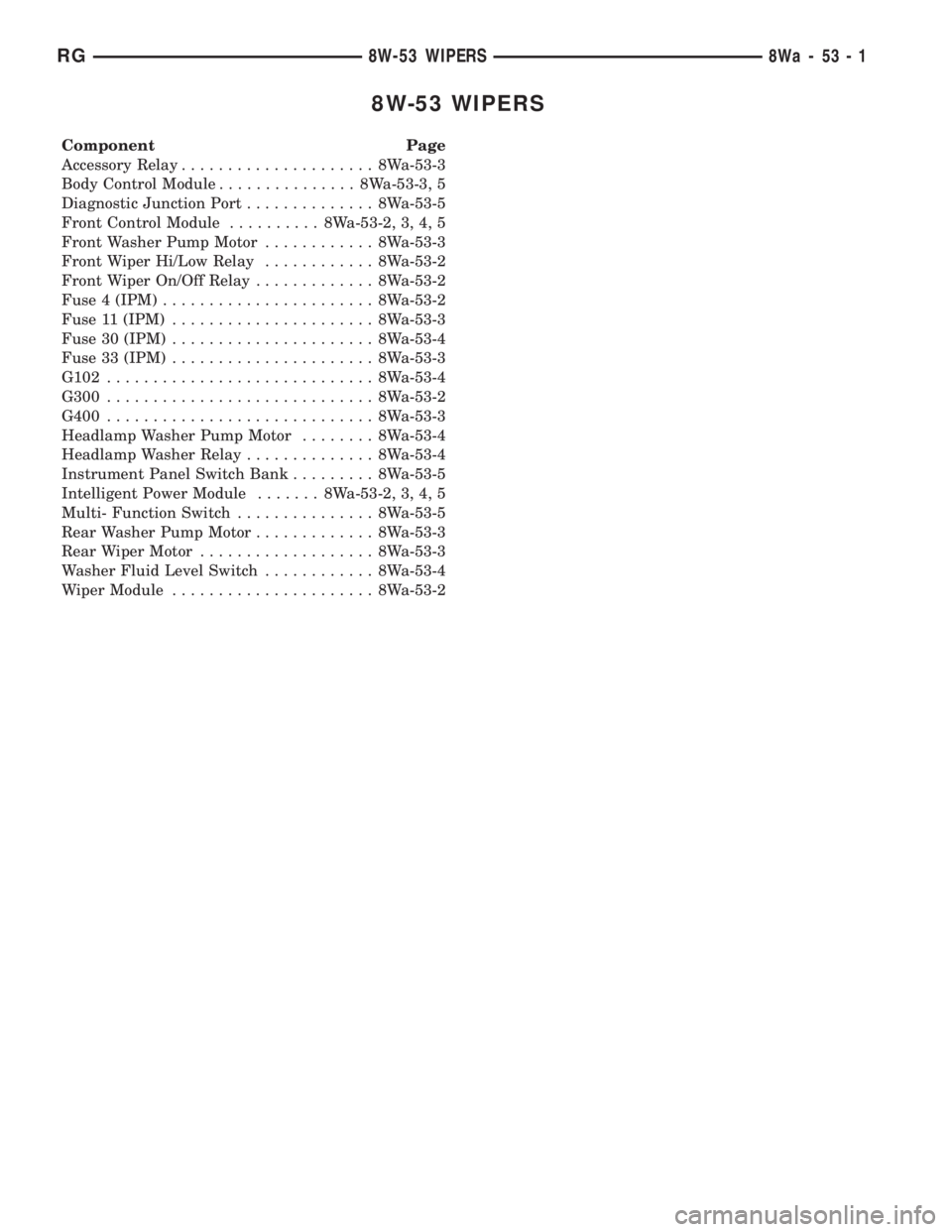
8W-53 WIPERS
Component Page
Accessory Relay..................... 8Wa-53-3
Body Control Module............... 8Wa-53-3, 5
Diagnostic Junction Port.............. 8Wa-53-5
Front Control Module.......... 8Wa-53-2, 3, 4, 5
Front Washer Pump Motor............ 8Wa-53-3
Front Wiper Hi/Low Relay............ 8Wa-53-2
Front Wiper On/Off Relay............. 8Wa-53-2
Fuse 4 (IPM)....................... 8Wa-53-2
Fuse 11 (IPM)...................... 8Wa-53-3
Fuse 30 (IPM)...................... 8Wa-53-4
Fuse 33 (IPM)...................... 8Wa-53-3
G102............................. 8Wa-53-4
G300............................. 8Wa-53-2
G400............................. 8Wa-53-3
Headlamp Washer Pump Motor........ 8Wa-53-4
Headlamp Washer Relay.............. 8Wa-53-4
Instrument Panel Switch Bank......... 8Wa-53-5
Intelligent Power Module....... 8Wa-53-2, 3, 4, 5
Multi- Function Switch............... 8Wa-53-5
Rear Washer Pump Motor............. 8Wa-53-3
Rear Wiper Motor................... 8Wa-53-3
Washer Fluid Level Switch............ 8Wa-53-4
Wiper Module...................... 8Wa-53-2
RG8W-53 WIPERS8Wa-53-1
Page 2445 of 4284
Component Page
Right Sliding Door Control Module C2
(Power Sliding Door).............. 8W-80-114
Right Sliding Door Latch Sensing Switch
(Power Sliding Door).............. 8W-80-114
Right Sliding Door Lock Motor
(Power Sliding Door).............. 8W-80-114
Right Sliding Door Lock Motor/
Ajar Switch (Manual Sliding Door) . . . 8W-80-115
Right Sliding Door Motor
(Power Sliding Door).............. 8W-80-115
Right Speed Control Switch.......... 8W-80-115
Right Stop/Turn Signal Relay
(Trailer Tow).................... 8W-80-115
Right Turn Signal Lamp
(Built-Up-Export)................ 8W-80-116
Right Visor/Vanity Lamp
(Premium/Luxury)................ 8W-80-116
Sentry Key Immobilizer Module....... 8W-80-116
Siren (United Kingdom)............. 8W-80-116
Solenoid/Pressure Switch Assy (EATX) . . 8W-80-117Component Page
Speed Control Servo (Gas)............ 8W-80-117
Speed Sensor-Input (EATX)........... 8W-80-117
Speed Sensor-Output (EATX)......... 8W-80-117
Thatcham Alarm Module C1
(United Kingdom)................ 8W-80-118
Thatcham Alarm Module C2
(United Kingdom)................ 8W-80-118
Throttle Position Sensor (Gas)......... 8W-80-118
Torque Converter Clutch Solenoid
(ATX).......................... 8W-80-118
Traction Control Switch.............. 8W-80-119
Trailer Tow Connector (Except
Built-Up-Export)................. 8W-80-119
Transmission Control Module (EATX) . . . 8W-80-119
Transmission Range Sensor (EATX).... 8W-80-120
TXV Solenoid (ATC)................ 8W-80-121
Vehicle Speed Sensor (MTX/ATX)...... 8W-80-121
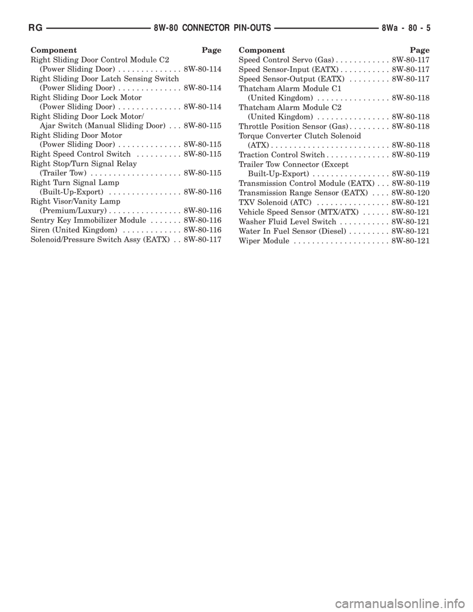
Washer Fluid Level Switch........... 8W-80-121
Water In Fuel Sensor (Diesel)......... 8W-80-121
Wiper Module..................... 8W-80-121
RG8W-80 CONNECTOR PIN-OUTS8Wa-80-5
Page 2507 of 4284
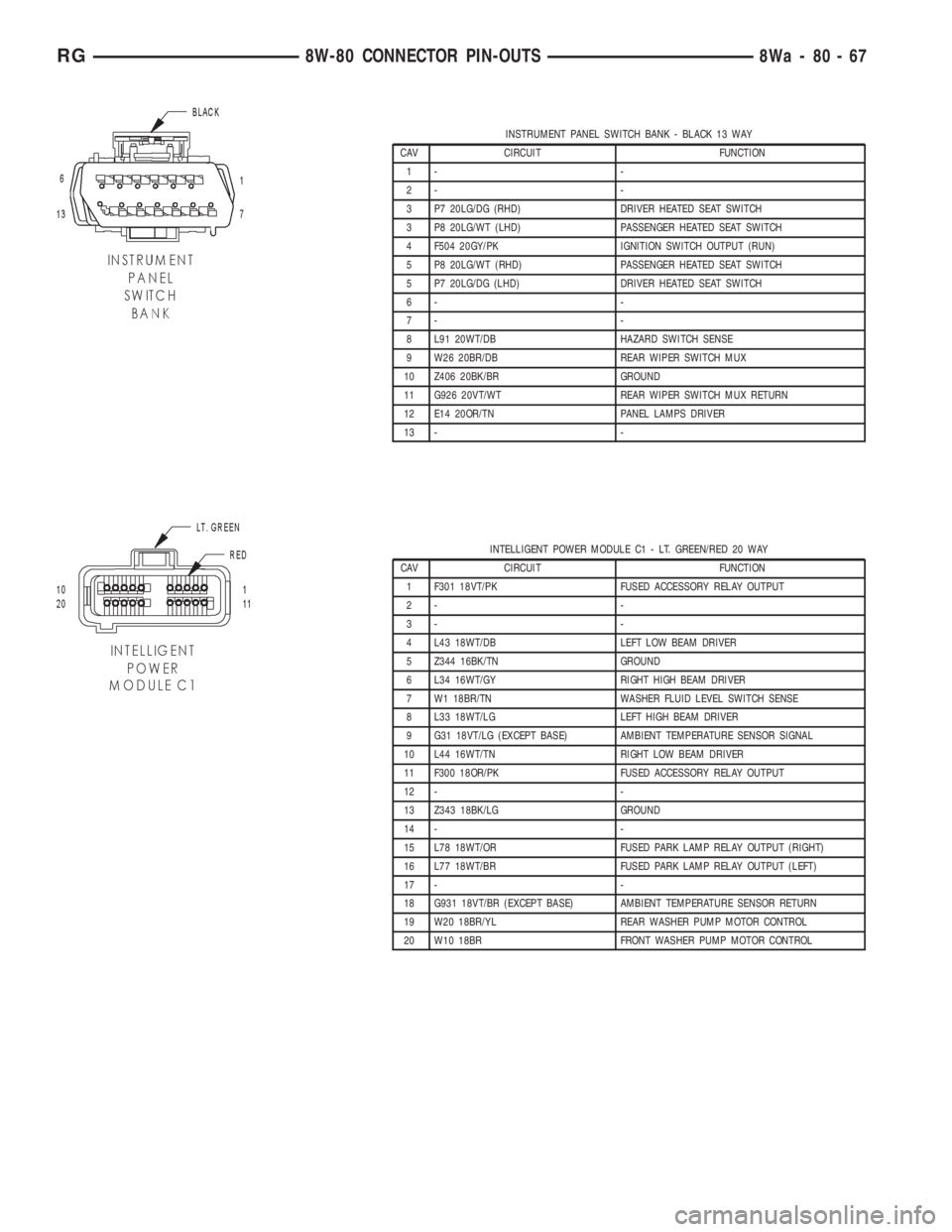
INSTRUMENT PANEL SWITCH BANK - BLACK 13 WAY
CAV CIRCUIT FUNCTION
1- -
2- -
3 P7 20LG/DG (RHD) DRIVER HEATED SEAT SWITCH
3 P8 20LG/WT (LHD) PASSENGER HEATED SEAT SWITCH
4 F504 20GY/PK IGNITION SWITCH OUTPUT (RUN)
5 P8 20LG/WT (RHD) PASSENGER HEATED SEAT SWITCH
5 P7 20LG/DG (LHD) DRIVER HEATED SEAT SWITCH
6- -
7- -
8 L91 20WT/DB HAZARD SWITCH SENSE
9 W26 20BR/DB REAR WIPER SWITCH MUX
10 Z406 20BK/BR GROUND
11 G926 20VT/WT REAR WIPER SWITCH MUX RETURN
12 E14 20OR/TN PANEL LAMPS DRIVER
13 - -
INTELLIGENT POWER MODULE C1 - LT. GREEN/RED 20 WAY
CAV CIRCUIT FUNCTION
1 F301 18VT/PK FUSED ACCESSORY RELAY OUTPUT
2- -
3- -
4 L43 18WT/DB LEFT LOW BEAM DRIVER
5 Z344 16BK/TN GROUND
6 L34 16WT/GY RIGHT HIGH BEAM DRIVER
7 W1 18BR/TN WASHER FLUID LEVEL SWITCH SENSE
8 L33 18WT/LG LEFT HIGH BEAM DRIVER
9 G31 18VT/LG (EXCEPT BASE) AMBIENT TEMPERATURE SENSOR SIGNAL
10 L44 16WT/TN RIGHT LOW BEAM DRIVER
11 F300 18OR/PK FUSED ACCESSORY RELAY OUTPUT
12 - -
13 Z343 18BK/LG GROUND
14 - -
15 L78 18WT/OR FUSED PARK LAMP RELAY OUTPUT (RIGHT)
16 L77 18WT/BR FUSED PARK LAMP RELAY OUTPUT (LEFT)
17 - -
18 G931 18VT/BR (EXCEPT BASE) AMBIENT TEMPERATURE SENSOR RETURN
19 W20 18BR/YL REAR WASHER PUMP MOTOR CONTROL
20 W10 18BR FRONT WASHER PUMP MOTOR CONTROL
RG8W-80 CONNECTOR PIN-OUTS8Wa-80-67
Page 2561 of 4284
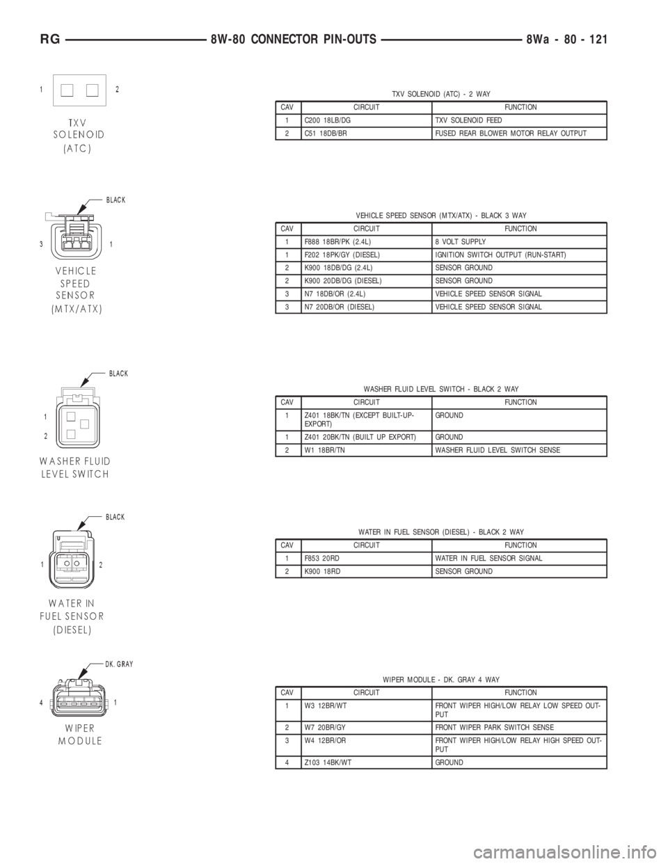
TXV SOLENOID (ATC)-2WAY
CAV CIRCUIT FUNCTION
1 C200 18LB/DG TXV SOLENOID FEED
2 C51 18DB/BR FUSED REAR BLOWER MOTOR RELAY OUTPUT
VEHICLE SPEED SENSOR (MTX/ATX) - BLACK 3 WAY
CAV CIRCUIT FUNCTION
1 F888 18BR/PK (2.4L) 8 VOLT SUPPLY
1 F202 18PK/GY (DIESEL) IGNITION SWITCH OUTPUT (RUN-START)
2 K900 18DB/DG (2.4L) SENSOR GROUND
2 K900 20DB/DG (DIESEL) SENSOR GROUND
3 N7 18DB/OR (2.4L) VEHICLE SPEED SENSOR SIGNAL
3 N7 20DB/OR (DIESEL) VEHICLE SPEED SENSOR SIGNAL
WASHER FLUID LEVEL SWITCH - BLACK 2 WAY
CAV CIRCUIT FUNCTION
1 Z401 18BK/TN (EXCEPT BUILT-UP-
EXPORT)GROUND
1 Z401 20BK/TN (BUILT UP EXPORT) GROUND
2 W1 18BR/TN WASHER FLUID LEVEL SWITCH SENSE
WATER IN FUEL SENSOR (DIESEL) - BLACK 2 WAY
CAV CIRCUIT FUNCTION
1 F853 20RD WATER IN FUEL SENSOR SIGNAL
2 K900 18RD SENSOR GROUND
WIPER MODULE - DK. GRAY 4 WAY
CAV CIRCUIT FUNCTION
1 W3 12BR/WT FRONT WIPER HIGH/LOW RELAY LOW SPEED OUT-
PUT
2 W7 20BR/GY FRONT WIPER PARK SWITCH SENSE
3 W4 12BR/OR FRONT WIPER HIGH/LOW RELAY HIGH SPEED OUT-
PUT
4 Z103 14BK/WT GROUND
RG8W-80 CONNECTOR PIN-OUTS8Wa - 80 - 121
Page 2573 of 4284
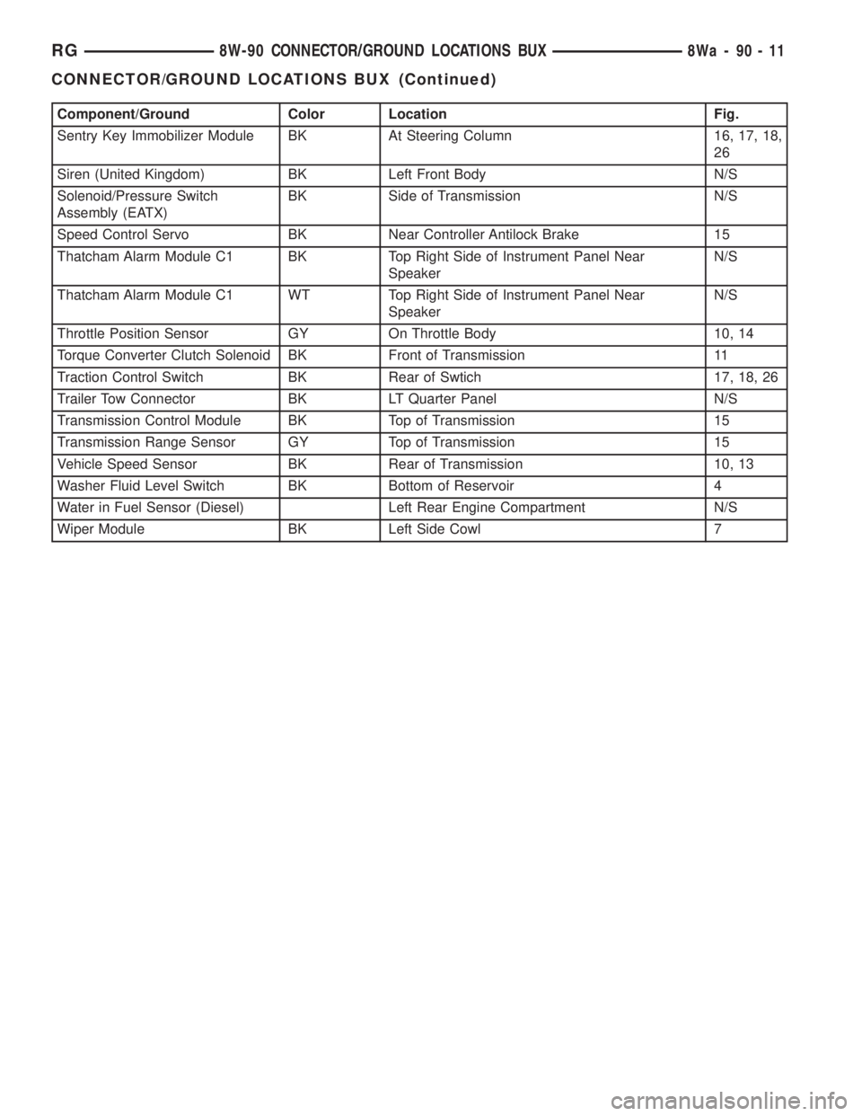
Component/Ground Color Location Fig.
Sentry Key Immobilizer Module BK At Steering Column 16, 17, 18,
26
Siren (United Kingdom) BK Left Front Body N/S
Solenoid/Pressure Switch
Assembly (EATX)BK Side of Transmission N/S
Speed Control Servo BK Near Controller Antilock Brake 15
Thatcham Alarm Module C1 BK Top Right Side of Instrument Panel Near
SpeakerN/S
Thatcham Alarm Module C1 WT Top Right Side of Instrument Panel Near
SpeakerN/S
Throttle Position Sensor GY On Throttle Body 10, 14
Torque Converter Clutch Solenoid BK Front of Transmission 11
Traction Control Switch BK Rear of Swtich 17, 18, 26
Trailer Tow Connector BK LT Quarter Panel N/S
Transmission Control Module BK Top of Transmission 15
Transmission Range Sensor GY Top of Transmission 15
Vehicle Speed Sensor BK Rear of Transmission 10, 13
Washer Fluid Level Switch BK Bottom of Reservoir 4
Water in Fuel Sensor (Diesel) Left Rear Engine Compartment N/S
Wiper Module BK Left Side Cowl 7
RG8W-90 CONNECTOR/GROUND LOCATIONS BUX8Wa-90-11
CONNECTOR/GROUND LOCATIONS BUX (Continued)
Page 2950 of 4284
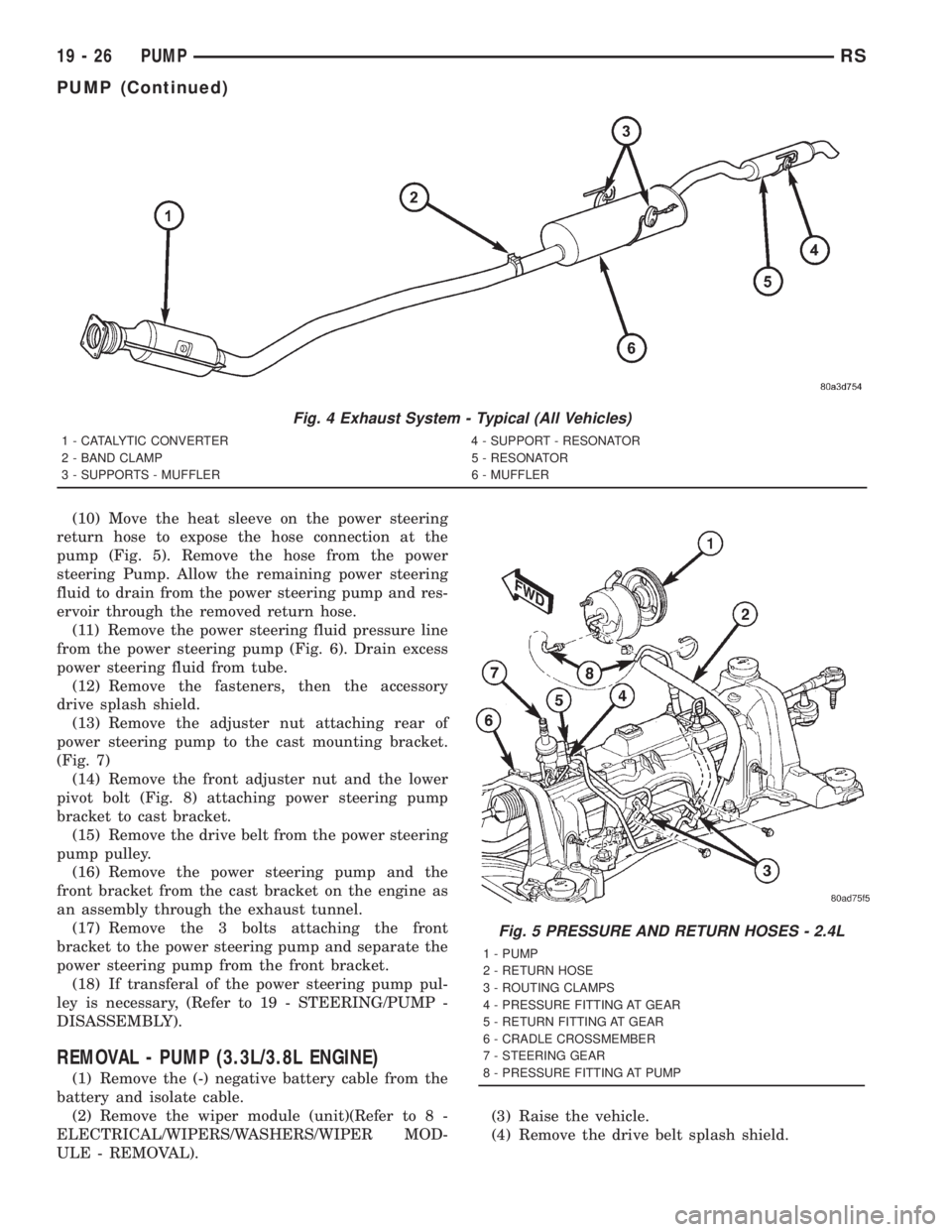
(10) Move the heat sleeve on the power steering
return hose to expose the hose connection at the
pump (Fig. 5). Remove the hose from the power
steering Pump. Allow the remaining power steering
fluid to drain from the power steering pump and res-
ervoir through the removed return hose.
(11) Remove the power steering fluid pressure line
from the power steering pump (Fig. 6). Drain excess
power steering fluid from tube.
(12) Remove the fasteners, then the accessory
drive splash shield.
(13) Remove the adjuster nut attaching rear of
power steering pump to the cast mounting bracket.
(Fig. 7)
(14) Remove the front adjuster nut and the lower
pivot bolt (Fig. 8) attaching power steering pump
bracket to cast bracket.
(15) Remove the drive belt from the power steering
pump pulley.
(16) Remove the power steering pump and the
front bracket from the cast bracket on the engine as
an assembly through the exhaust tunnel.
(17) Remove the 3 bolts attaching the front
bracket to the power steering pump and separate the
power steering pump from the front bracket.
(18) If transferal of the power steering pump pul-
ley is necessary, (Refer to 19 - STEERING/PUMP -
DISASSEMBLY).
REMOVAL - PUMP (3.3L/3.8L ENGINE)
(1) Remove the (-) negative battery cable from the
battery and isolate cable.
(2) Remove the wiper module (unit)(Refer to 8 -
ELECTRICAL/WIPERS/WASHERS/WIPER MOD-
ULE - REMOVAL).(3) Raise the vehicle.
(4) Remove the drive belt splash shield.
Fig. 4 Exhaust System - Typical (All Vehicles)
1 - CATALYTIC CONVERTER 4 - SUPPORT - RESONATOR
2 - BAND CLAMP 5 - RESONATOR
3 - SUPPORTS - MUFFLER 6 - MUFFLER
Fig. 5 PRESSURE AND RETURN HOSES - 2.4L
1 - PUMP
2 - RETURN HOSE
3 - ROUTING CLAMPS
4 - PRESSURE FITTING AT GEAR
5 - RETURN FITTING AT GEAR
6 - CRADLE CROSSMEMBER
7 - STEERING GEAR
8 - PRESSURE FITTING AT PUMP
19 - 26 PUMPRS
PUMP (Continued)
Page 2954 of 4284
(4) Install the power steering fluid pressure line
into the pressure output fitting of the power steering
pump (Fig. 11). Tighten the pressure line to pump fit-
ting tube nut to a torque of 31 N´m (275 in. lbs.).
(5) Install the power steering fluid low-pressure
return hose on the power steering pump low pressure
fitting (Fig. 11).Be sure hose clamps are prop-
erly reinstalled.
(6) Raise the vehicle.
(7) Install the routing clip on the engine for the
pressure hose (Fig. 10).
(8) Tighten the pump thru-bolt (Fig. 9). Tighten to
54 N´m (40 ft. lbs.) torque.
(9) Install the serpentine drive belt (Refer to 7 -
COOLING/ACCESSORY DRIVE/DRIVE BELTS -
INSTALLATION).
(10) Install the drive belt splash shield.
(11) Lower the vehicle.
(12) Install the wiper module (unit)(Refer to 8 -
ELECTRICAL/WIPERS/WASHERS/WIPER MOD-
ULE - INSTALLATION).
(13) Connect the negative battery cable on the
negative battery post.
(14) Fill and bleed the power steering system
using the Power Steering Pump Initial Operation
Procedure (Refer to 19 - STEERING/PUMP - STAN-
DARD PROCEDURE).
(15) Inspect for leaks.
SPECIAL TOOLS
POWER STEERING PUMP
FLUID
STANDARD PROCEDURE - POWER STEERING
FLUID LEVEL CHECKING
WARNING: FLUID LEVEL SHOULD BE CHECKED
WITH THE ENGINE OFF TO PREVENT INJURY
FROM MOVING PARTS.
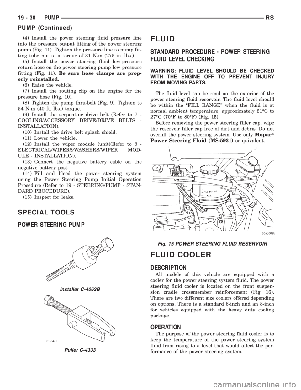
The fluid level can be read on the exterior of the
power steering fluid reservoir. The fluid level should
be within the ªFILL RANGEº when the fluid is at
normal ambient temperature, approximately 21ÉC to
27ÉC (70ÉF to 80ÉF) (Fig. 15).
Before removing the power steering filler cap, wipe
the reservoir filler cap free of dirt and debris. Do not
overfill the power steering system. Use onlyMopart
Power Steering Fluid (MS-5931)or quivalent.
FLUID COOLER
DESCRIPTION
All models of this vehicle are equipped with a
cooler for the power steering system fluid. The power
steering fluid cooler is located on the front suspen-
sion cradle crossmember reinforcement (Fig. 16).
There are two different size coolers offered depending
on options. There is a standard 6-inch and an 8-inch
for vehicles equipped with the heavy duty cooling
package.
OPERATION
The purpose of the power steering fluid cooler is to
keep the temperature of the power steering system
fluid from rising to a level that would affect the per-
formance of the power steering system.
Installer C-4063B
Puller C-4333
Fig. 15 POWER STEERING FLUID RESERVOIR
19 - 30 PUMPRS
PUMP (Continued)