2001 CHRYSLER VOYAGER torque
[x] Cancel search: torquePage 1740 of 4284
SPECIFICATIONS
TORQUE
DESCRIPTION N´mFt.
Lbs.In.
Lbs.
Accessory Drive Belt Tensioner
Assembly (3.3/3.8L)ÐBolt28 Ð 250
Generator & A/C Compressor Drive
Belt Tensioner Assembly (2.4L)Ð
Bolt28 Ð 250
Coolant Outlet Connector/
Thermostat Housing
(2.4 & 3.3/3.8L)ÐBolts 28 Ð 250
Water Pump
(2.4 & 3.3/3.8L)ÐBolts 12 Ð 105
Water Pump Inlet Tube (2.4L)Ð
Bolts12 Ð 105
Water Pump Inlet Tube (3.3/3.8L)Ð
Bolts28 Ð 250
Water Pump Pulley (3.3/3.8L)Ð
Bolts28 Ð 250
Radiator to A/C CondenserÐ
Screws5Ð45
Radiator FanÐScrews 5 Ð 45
Radiator Mounting (Upper
Bracket)ÐNuts8Ð70
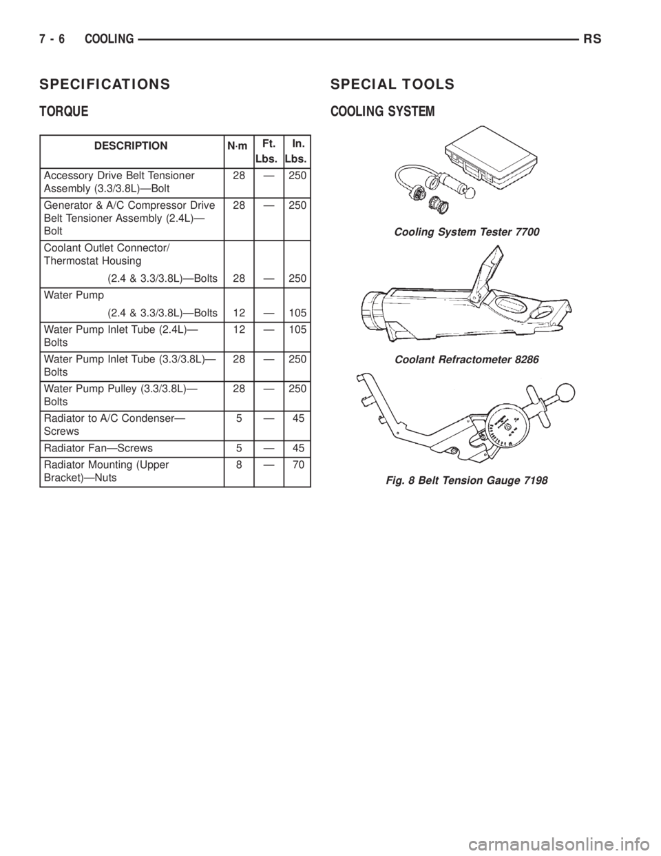
SPECIAL TOOLS
COOLING SYSTEM
Cooling System Tester 7700
Coolant Refractometer 8286
Fig. 8 Belt Tension Gauge 7198
7 - 6 COOLINGRS
Page 1744 of 4284
CLEANING
Clean all foreign debris from belt pulley grooves.
The belt pulleys must be free of oil, grease, and cool-
ants before installing the drive belt.
INSPECTION
Belt replacement under any or all of the following
conditions is required:
²Excessive wear
²Frayed cords
²Severe glazing
Poly-V Belt system may develop minor cracks
across the ribbed side (due to reverse bending). These
minor cracks are considered normal and acceptable.
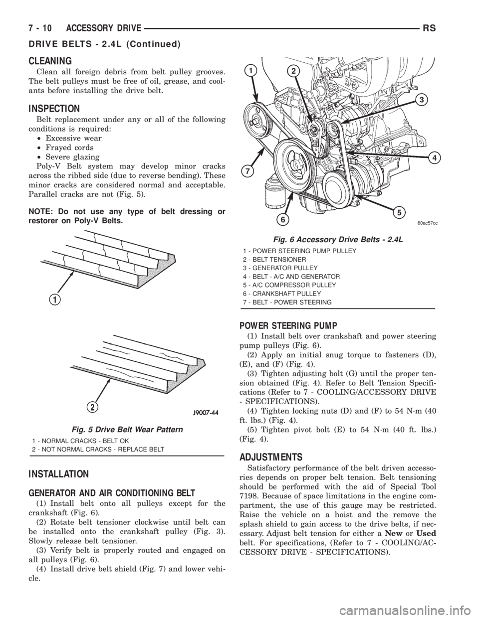
Parallel cracks are not (Fig. 5).
NOTE: Do not use any type of belt dressing or
restorer on Poly-V Belts.
INSTALLATION
GENERATOR AND AIR CONDITIONING BELT
(1) Install belt onto all pulleys except for the
crankshaft (Fig. 6).
(2) Rotate belt tensioner clockwise until belt can
be installed onto the crankshaft pulley (Fig. 3).
Slowly release belt tensioner.
(3) Verify belt is properly routed and engaged on
all pulleys (Fig. 6).
(4) Install drive belt shield (Fig. 7) and lower vehi-
cle.
POWER STEERING PUMP
(1) Install belt over crankshaft and power steering
pump pulleys (Fig. 6).
(2) Apply an initial snug torque to fasteners (D),
(E), and (F) (Fig. 4).
(3) Tighten adjusting bolt (G) until the proper ten-
sion obtained (Fig. 4). Refer to Belt Tension Specifi-
cations (Refer to 7 - COOLING/ACCESSORY DRIVE
- SPECIFICATIONS).
(4) Tighten locking nuts (D) and (F) to 54 N´m (40
ft. lbs.) (Fig. 4).
(5) Tighten pivot bolt (E) to 54 N´m (40 ft. lbs.)
(Fig. 4).
ADJUSTMENTS
Satisfactory performance of the belt driven accesso-
ries depends on proper belt tension. Belt tensioning
should be performed with the aid of Special Tool
7198. Because of space limitations in the engine com-
partment, the use of this gauge may be restricted.
Raise the vehicle on a hoist and the remove the
splash shield to gain access to the drive belts, if nec-
essary. Adjust belt tension for either aNeworUsed
belt. For specifications, (Refer to 7 - COOLING/AC-
CESSORY DRIVE - SPECIFICATIONS).
Fig. 5 Drive Belt Wear Pattern
1 - NORMAL CRACKS - BELT OK
2 - NOT NORMAL CRACKS - REPLACE BELT
Fig. 6 Accessory Drive Belts - 2.4L
1 - POWER STEERING PUMP PULLEY
2 - BELT TENSIONER
3 - GENERATOR PULLEY
4 - BELT - A/C AND GENERATOR
5 - A/C COMPRESSOR PULLEY
6 - CRANKSHAFT PULLEY
7 - BELT - POWER STEERING
7 - 10 ACCESSORY DRIVERS
DRIVE BELTS - 2.4L (Continued)
Page 1765 of 4284
(13) Remove water pump attaching screws to
engine (Fig. 25).
CLEANING
Clean gasket mating surfaces as necessary.
INSPECTION
Replace water pump body assembly if it has any of
these defects:
(1) Cracks or damage on the body.
(2) Coolant leaks from the shaft seal, evident by
wet coolant traces on the pump body.
(3) Loose or rough turning bearing.
(4) Impeller rubs either the pump body or the
engine block.
(5) Impeller loose or damaged.
(6) Sprocket or sprocket flange loose or damaged.
INSTALLATION
(1) Install new O-ring gasket in water pump body
O-ring groove (Fig. 26).
CAUTION: Make sure O-ring is properly seated in
water pump groove before tightening screws. Animproperly located O-ring may be damaged and
cause a coolant leak.
(2) Assemble pump body to block and tighten
screws to 12 N´m (105 in. lbs.) (Fig. 25). Pressurize
cooling system to 103.4 Kpa (15 psi) with pressure
tester and check water pump shaft seal and O-ring
for leaks.
(3) Rotate pump by hand to check for freedom of
movement.
(4) Install the timing belt rear cover. (Refer to 9 -
ENGINE/VALVE TIMING/TIMING BELT / CHAIN
COVER(S) - INSTALLATION)
(5) Install camshaft sprockets and torque bolts to
101 N´m (75 ft. lbs.).
(6) Install timing belt idler pulley and torque
mounting bolt to 61 N´m (45 ft. lbs.).
(7) Install the timing belt. (Refer to 9 - ENGINE/
VALVE TIMING/TIMING BELT/CHAIN AND
SPROCKET(S - INSTALLATION)
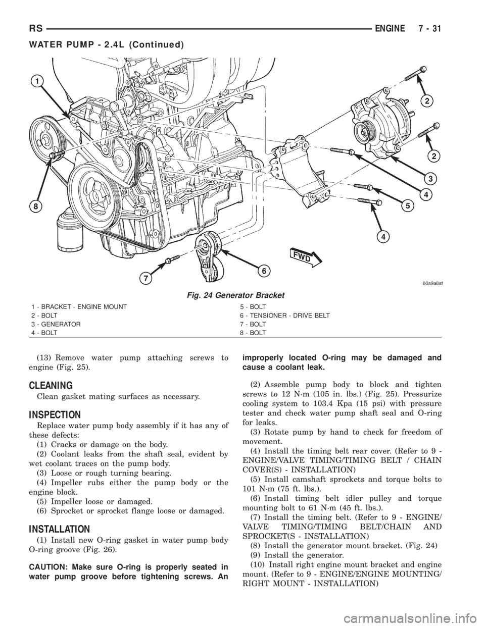
(8) Install the generator mount bracket. (Fig. 24)
(9) Install the generator.
(10) Install right engine mount bracket and engine
mount. (Refer to 9 - ENGINE/ENGINE MOUNTING/
RIGHT MOUNT - INSTALLATION)
Fig. 24 Generator Bracket
1 - BRACKET - ENGINE MOUNT 5 - BOLT
2 - BOLT 6 - TENSIONER - DRIVE BELT
3 - GENERATOR 7 - BOLT
4 - BOLT 8 - BOLT
RSENGINE7-31
WATER PUMP - 2.4L (Continued)
Page 1782 of 4284
SPECIFICATIONS
SPECIFICATIONS - TORQUE
2.5L DIESEL - TORQUE SPECIFICATIONS
DESCRIPTION N´m Ft. Lbs. In. Lbs.
Water Pump Housing Nuts 24.4 18 215
Thermostat Housing Bolts 27.5 21 Ð
Accessory Drive Belt
Tensioner Bolt47.1 35 Ð
Accessory Drive Belt Idler
Bolt53 39 Ð
SPECIFICATIONS - COOLING SYSTEM
CAPACITY
SPECIFICATIONS
DESCRIPTION SPECIFICATION
Cooling System With
Auxiliary Heater16.6 Liters (17.5 qts.)
Cooling System With Out
Auxiliary Heater13.8 Liters (14.6 qts.)
7a - 8 COOLING 2.5L TURBO DIESELRG
COOLING 2.5L TURBO DIESEL (Continued)
Page 1783 of 4284
ACCESSORY DRIVE
TABLE OF CONTENTS
page page
ACCESSORY DRIVE
SPECIFICATIONS.........................9
BELT TENSIONER
REMOVAL...............................9
INSTALLATION............................9
IDLER PULLEY
REMOVAL..............................10
INSTALLATION...........................10DRIVE BELTS
DESCRIPTION...........................10
OPERATION.............................10
DIAGNOSIS AND TESTING.................11
ACCESSORY DRIVE BELT................11
REMOVAL..............................11
INSTALLATION...........................11
ACCESSORY DRIVE
SPECIFICATIONS
SPECIFICATIONS - ACCESSORY BELT TENSION
ACCESSORY DRIVE
BELTGAUGE
2.5L DIESEL ENGINE
A/C Compressor/
GeneratorDynamic Tensioner
Power Steering Belt 300 N (67 lbs.)
BELT TENSIONER
REMOVAL
WARNING: BECAUSE OF HIGH SPRING TENSION,
DO NOT ATTEMPT TO DISASSEMBLE THE AUTO-
MATIC BELT TENSIONER. THE TENSIONER IS SER-
VICED AS AN ASSEMBLY.
(1) Remove the power steering belt (Refer to 7 -
COOLING/ACCESSORY DRIVE/DRIVE BELTS -
REMOVAL).
(2) Remove the accessory drive belt (Refer to 7 -
COOLING/ACCESSORY DRIVE/DRIVE BELTS -
INSTALLATION).
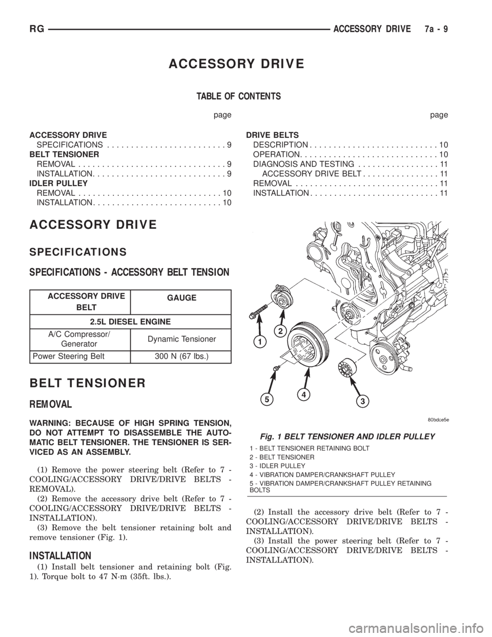
(3) Remove the belt tensioner retaining bolt and
remove tensioner (Fig. 1).
INSTALLATION
(1) Install belt tensioner and retaining bolt (Fig.
1). Torque bolt to 47 N´m (35ft. lbs.).(2) Install the accessory drive belt (Refer to 7 -
COOLING/ACCESSORY DRIVE/DRIVE BELTS -
INSTALLATION).
(3) Install the power steering belt (Refer to 7 -
COOLING/ACCESSORY DRIVE/DRIVE BELTS -
INSTALLATION).
Fig. 1 BELT TENSIONER AND IDLER PULLEY
1 - BELT TENSIONER RETAINING BOLT
2 - BELT TENSIONER
3 - IDLER PULLEY
4 - VIBRATION DAMPER/CRANKSHAFT PULLEY
5 - VIBRATION DAMPER/CRANKSHAFT PULLEY RETAINING
BOLTS
RGACCESSORY DRIVE7a-9
Page 1784 of 4284
IDLER PULLEY
REMOVAL
(1) Remove the accessory drive belt (Refer to 7 -
COOLING/ACCESSORY DRIVE/DRIVE BELTS -
REMOVAL).
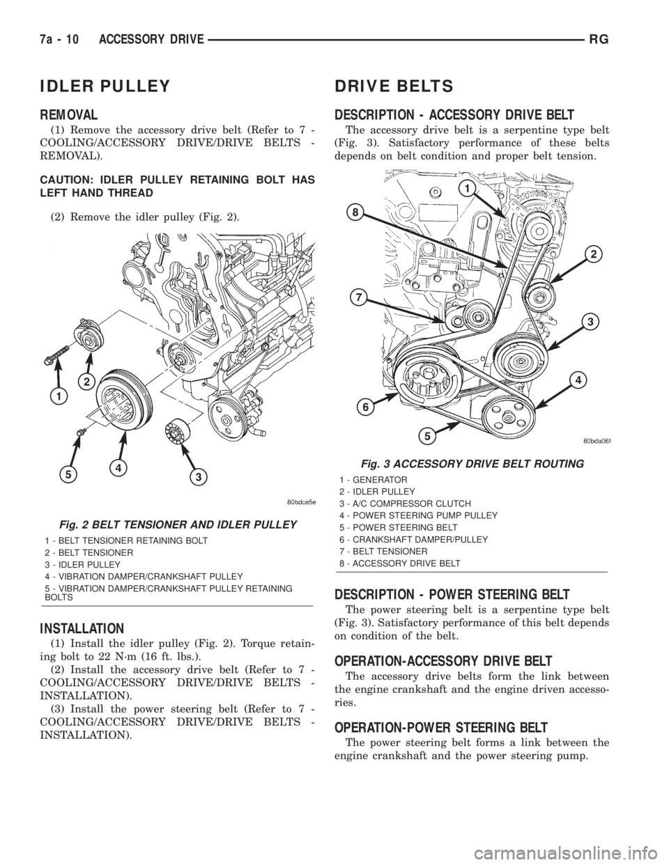
CAUTION: IDLER PULLEY RETAINING BOLT HAS
LEFT HAND THREAD
(2) Remove the idler pulley (Fig. 2).
INSTALLATION
(1) Install the idler pulley (Fig. 2). Torque retain-
ing bolt to 22 N´m (16 ft. lbs.).
(2) Install the accessory drive belt (Refer to 7 -
COOLING/ACCESSORY DRIVE/DRIVE BELTS -
INSTALLATION).
(3) Install the power steering belt (Refer to 7 -
COOLING/ACCESSORY DRIVE/DRIVE BELTS -
INSTALLATION).
DRIVE BELTS
DESCRIPTION - ACCESSORY DRIVE BELT
The accessory drive belt is a serpentine type belt
(Fig. 3). Satisfactory performance of these belts
depends on belt condition and proper belt tension.
DESCRIPTION - POWER STEERING BELT
The power steering belt is a serpentine type belt
(Fig. 3). Satisfactory performance of this belt depends
on condition of the belt.
OPERATION-ACCESSORY DRIVE BELT
The accessory drive belts form the link between
the engine crankshaft and the engine driven accesso-
ries.
OPERATION-POWER STEERING BELT
The power steering belt forms a link between the
engine crankshaft and the power steering pump.
Fig. 2 BELT TENSIONER AND IDLER PULLEY
1 - BELT TENSIONER RETAINING BOLT
2 - BELT TENSIONER
3 - IDLER PULLEY
4 - VIBRATION DAMPER/CRANKSHAFT PULLEY
5 - VIBRATION DAMPER/CRANKSHAFT PULLEY RETAINING
BOLTS
Fig. 3 ACCESSORY DRIVE BELT ROUTING
1 - GENERATOR
2 - IDLER PULLEY
3 - A/C COMPRESSOR CLUTCH
4 - POWER STEERING PUMP PULLEY
5 - POWER STEERING BELT
6 - CRANKSHAFT DAMPER/PULLEY
7 - BELT TENSIONER
8 - ACCESSORY DRIVE BELT
7a - 10 ACCESSORY DRIVERG
Page 1794 of 4284
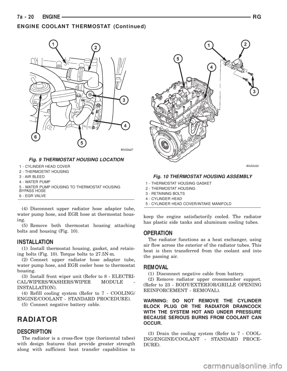
(4) Disconnect upper radiator hose adapter tube,
water pump hose, and EGR hose at thermostat hous-
ing.
(5) Remove both thermostat housing attaching
bolts and housing (Fig. 10).
INSTALLATION
(1) Install thermostat housing, gasket, and retain-
ing bolts (Fig. 10). Torque bolts to 27.5N´m.
(2) Connect upper radiator hose adapter tube,
water pump hose, and EGR cooler hose to thermostat
housing.
(3) Install front wiper unit (Refer to 8 - ELECTRI-
CAL/WIPERS/WASHERS/WIPER MODULE -
INSTALLATION).
(4) Refill cooling system (Refer to 7 - COOLING/
ENGINE/COOLANT - STANDARD PROCEDURE).
(5) Connect negative battery cable.
RADIATOR
DESCRIPTION
The radiator is a cross-flow type (horizontal tubes)
with design features that provide greater strength
along with sufficient heat transfer capabilities tokeep the engine satisfactorily cooled. The radiator
has plastic side tanks and aluminum cooling tubes.
OPERATION
The radiator functions as a heat exchanger, using
air flow across the exterior of the radiator tubes. This
heat is then transferred from the coolant and into
the passing air.
REMOVAL
(1) Disconnect negative cable from battery.
(2) Remove radiator upper crossmember support.
(Refer to 23 - BODY/EXTERIOR/GRILLE OPENING
REINFORCEMENT - REMOVAL).
WARNING: DO NOT REMOVE THE CYLINDER
BLOCK PLUG OR THE RADIATOR DRAINCOCK
WITH THE SYSTEM HOT AND UNDER PRESSURE
BECAUSE SERIOUS BURNS FROM COOLANT CAN
OCCUR.
(3) Drain the cooling system (Refer to 7 - COOL-
ING/ENGINE/COOLANT - STANDARD PROCE-
DURE).
Fig. 9 THERMOSTAT HOUSING LOCATION
1 - CYLINDER HEAD COVER
2 - THERMOSTAT HOUSING
3 - AIR BLEED
4 - WATER PUMP
5 - WATER PUMP HOUSING TO THERMOSTAT HOUSING
BYPASS HOSE
6 - E G R VA LV E
Fig. 10 THERMOSTAT HOUSING ASSEMBLY
1 - THERMOSTAT HOUSING GASKET
2 - THERMOSTAT HOUSING
3 - RETAINING BOLTS
4 - CYLINDER HEAD
5 - CYLINDER HEAD COVER/INTAKE MANIFOLD
7a - 20 ENGINERG
ENGINE COOLANT THERMOSTAT (Continued)
Page 1797 of 4284
REMOVAL - WATER PUMP HOUSING
(1) Disconnect negative battery cable.
(2) Drain cooling system (Refer to 7 - COOLING/
ENGINE/COOLANT - STANDARD PROCEDURE).
(3) Remove both outer and inner timing belt covers
(Refer to 9 - ENGINE/VALVE TIMING/TIMING
BELT / CHAIN COVER(S) - REMOVAL).
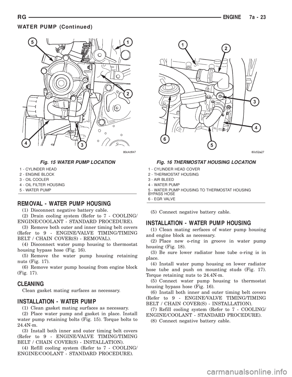
(4) Disconnect water pump housing to thermostat
housing bypass hose (Fig. 16).
(5) Remove the water pump housing retaining
nuts (Fig. 17).
(6) Remove water pump housing from engine block
(Fig. 17).
CLEANING
Clean gasket mating surfaces as necessary.
INSTALLATION - WATER PUMP
(1) Clean gasket mating surfaces as necessary.
(2) Place water pump and gasket in place. Install
water pump retaining bolts (Fig. 15). Torque bolts to
24.4N´m.
(3) Install both inner and outer timing belt covers
(Refer to 9 - ENGINE/VALVE TIMING/TIMING
BELT / CHAIN COVER(S) - INSTALLATION).
(4) Refill cooling system (Refer to 7 - COOLING/
ENGINE/COOLANT - STANDARD PROCEDURE).(5) Connect negative battery cable.
INSTALLATION - WATER PUMP HOUSING
(1) Clean mating serfaces of water pump housing
and engine block as necessary.
(2) Place new o-ring in groove in water pump
housing (Fig. 18).
(3) Be sure lower radiator hose tube o-ring is in
place.
(4) Install water pump housing on lower radiator
hose tube and push on mounting studs (Fig. 17).
Torque retaining nuts to 24.4N´m.
(5) Connect water pump housing to thermostat
housing bypass hose (Fig. 16).
(6) Install both inner and outer timing belt covers
(Refer to 9 - ENGINE/VALVE TIMING/TIMING
BELT / CHAIN COVER(S) - INSTALLATION).
(7) Refill cooling system (Refer to 7 - COOLING/
ENGINE/COOLANT - STANDARD PROCEDURE).
(8) Connect negative battery cable.
Fig. 15 WATER PUMP LOCATION
1 - CYLINDER HEAD
2 - ENGINE BLOCK
3 - OIL COOLER
4 - OIL FILTER HOUSING
5 - WATER PUMP
Fig. 16 THERMOSTAT HOUSING LOCATION
1 - CYLINDER HEAD COVER
2 - THERMOSTAT HOUSING
3 - AIR BLEED
4 - WATER PUMP
5 - WATER PUMP HOUSING TO THERMOSTAT HOUSING
BYPASS HOSE
6 - E G R VA LV E
RGENGINE7a-23
WATER PUMP (Continued)