2001 CHRYSLER VOYAGER torque
[x] Cancel search: torquePage 1925 of 4284
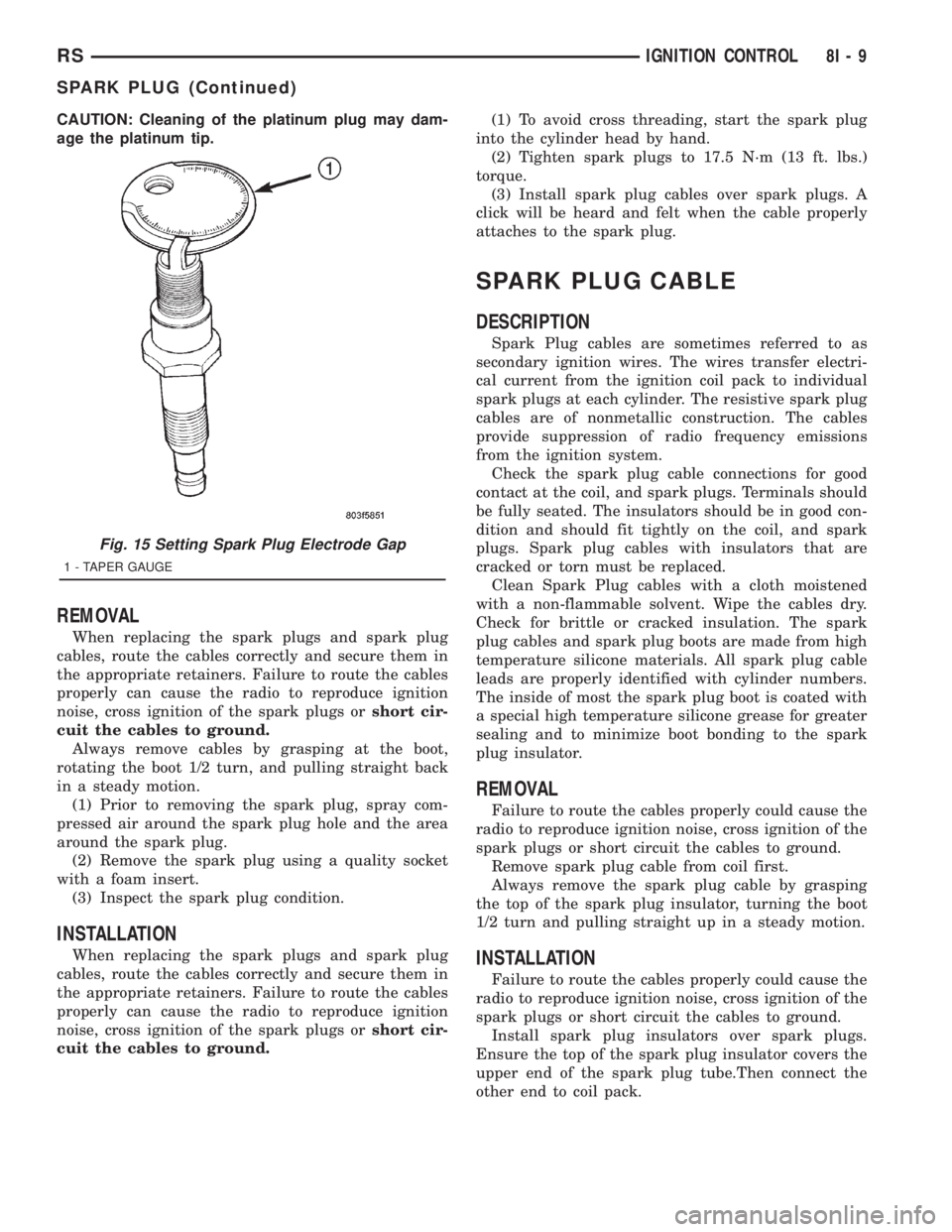
CAUTION: Cleaning of the platinum plug may dam-
age the platinum tip.
REMOVAL
When replacing the spark plugs and spark plug
cables, route the cables correctly and secure them in
the appropriate retainers. Failure to route the cables
properly can cause the radio to reproduce ignition
noise, cross ignition of the spark plugs orshort cir-
cuit the cables to ground.
Always remove cables by grasping at the boot,
rotating the boot 1/2 turn, and pulling straight back
in a steady motion.
(1) Prior to removing the spark plug, spray com-
pressed air around the spark plug hole and the area
around the spark plug.
(2) Remove the spark plug using a quality socket
with a foam insert.
(3) Inspect the spark plug condition.
INSTALLATION
When replacing the spark plugs and spark plug
cables, route the cables correctly and secure them in
the appropriate retainers. Failure to route the cables
properly can cause the radio to reproduce ignition
noise, cross ignition of the spark plugs orshort cir-
cuit the cables to ground.(1) To avoid cross threading, start the spark plug
into the cylinder head by hand.
(2) Tighten spark plugs to 17.5 N´m (13 ft. lbs.)
torque.
(3) Install spark plug cables over spark plugs. A
click will be heard and felt when the cable properly
attaches to the spark plug.
SPARK PLUG CABLE
DESCRIPTION
Spark Plug cables are sometimes referred to as
secondary ignition wires. The wires transfer electri-
cal current from the ignition coil pack to individual
spark plugs at each cylinder. The resistive spark plug
cables are of nonmetallic construction. The cables
provide suppression of radio frequency emissions
from the ignition system.
Check the spark plug cable connections for good
contact at the coil, and spark plugs. Terminals should
be fully seated. The insulators should be in good con-
dition and should fit tightly on the coil, and spark
plugs. Spark plug cables with insulators that are
cracked or torn must be replaced.
Clean Spark Plug cables with a cloth moistened
with a non-flammable solvent. Wipe the cables dry.
Check for brittle or cracked insulation. The spark
plug cables and spark plug boots are made from high
temperature silicone materials. All spark plug cable
leads are properly identified with cylinder numbers.
The inside of most the spark plug boot is coated with
a special high temperature silicone grease for greater
sealing and to minimize boot bonding to the spark
plug insulator.
REMOVAL
Failure to route the cables properly could cause the
radio to reproduce ignition noise, cross ignition of the
spark plugs or short circuit the cables to ground.
Remove spark plug cable from coil first.
Always remove the spark plug cable by grasping
the top of the spark plug insulator, turning the boot
1/2 turn and pulling straight up in a steady motion.
INSTALLATION
Failure to route the cables properly could cause the
radio to reproduce ignition noise, cross ignition of the
spark plugs or short circuit the cables to ground.
Install spark plug insulators over spark plugs.
Ensure the top of the spark plug insulator covers the
upper end of the spark plug tube.Then connect the
other end to coil pack.
Fig. 15 Setting Spark Plug Electrode Gap
1 - TAPER GAUGE
RSIGNITION CONTROL8I-9
SPARK PLUG (Continued)
Page 1974 of 4284
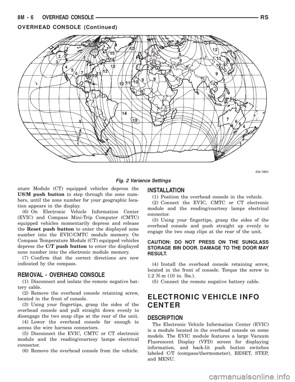
ature Module (CT) equipped vehicles depress the
US/M push buttonto step through the zone num-
bers, until the zone number for your geographic loca-
tion appears in the display.
(6) On Electronic Vehicle Information Center
(EVIC) and Compass Mini-Trip Computer (CMTC)
equipped vehicles momentarily depress and release
theReset push buttonto enter the displayed zone
number into the EVIC/CMTC module memory. On
Compass Temperature Module (CT) equipped vehicles
depress theC/T push buttonto enter the displayed
zone number into the electronic module memory.
(7) Confirm that the correct directions are now
indicated by the compass.
REMOVAL - OVERHEAD CONSOLE
(1) Disconnect and isolate the remote negative bat-
tery cable.
(2) Remove the overhead console retaining screw,
located in the front of console.
(3) Using your fingertips, grasp the sides of the
overhead console and pull straight down evenly to
disengage the two snap clips at the rear of the unit.
(4) Lower the overhead console far enough to
access the wire harness connectors.
(5) Disconnect the EVIC, CMTC or CT electronic
module and the reading/courtesy lamps electrical
connector.
(6) Remove the overhead console from the vehicle.
INSTALLATION
(1) Position the overhead console in the vehicle.
(2) Connect the EVIC, CMTC or CT electronic
module and the reading/courtesy lamps electrical
connector.
(3) Using your fingertips, grasp the sides of the
overhead console and push straight up evenly to
engage the two snap clips at the rear of the unit.
CAUTION: DO NOT PRESS ON THE SUNGLASS
STORAGE BIN DOOR. DAMAGE TO THE DOOR MAY
RESULT.
(4) Install the overhead console retaining screw,
located in the front of console. Torque the screw to
1.2 N´m (10 in. lbs.).
(5) Connect the remote negative battery cable.
ELECTRONIC VEHICLE INFO
CENTER
DESCRIPTION
The Electronic Vehicle Information Center (EVIC)
is a module located in the overhead console on some
models. The EVIC module features a large Vacuum
Fluorescent Display (VFD) screen for displaying
information, and back-lit push button switches
labeled C/T (compass/thermometer), RESET, STEP,
and MENU.
Fig. 2 Variance Settings
8M - 6 OVERHEAD CONSOLERS
OVERHEAD CONSOLE (Continued)
Page 1990 of 4284
(3) Disconnect the pinch sensor wire harness con-
nector (Fig. 4).
(4) Remove screws holding the pinch sensor to lift-
gate.
(5) Feed the pinch sensor wire harness out of the
liftgate and remove the sensor from the vehicle.
INSTALLATION
(1) Position the pinch sensor and install screws
holding the sensor to the liftgate. Torque screws to
25 in. lbs.
(2) Install wire harness grommet in liftgate flange
and route, connect the pinch sensor wire harness
connector.
(3) Install the trim panel on the liftgate. Refer to
the Body section for the procedure.
(4) Connect the negative battery cable.
(5) Using an appropriate scan tool, check and
erase any power liftgate control module diagnostic
trouble codes related to the pinch sensor.
(6) Verify power liftgate system and pinch sensor
operation. Cycle the power liftgate through one com-
plete open and close cycle, during the final close cycle
press the pinch sensor to verify the power liftgate
detects an obstruction and returns to the full open
position.
WARNING: USE EXTREME CAUTION WHEN TEST-
ING PINCH SENSOR OPERATION.
FULL OPEN SWITCH
DESCRIPTION
Vehicles equipped with a power liftgate utilize a
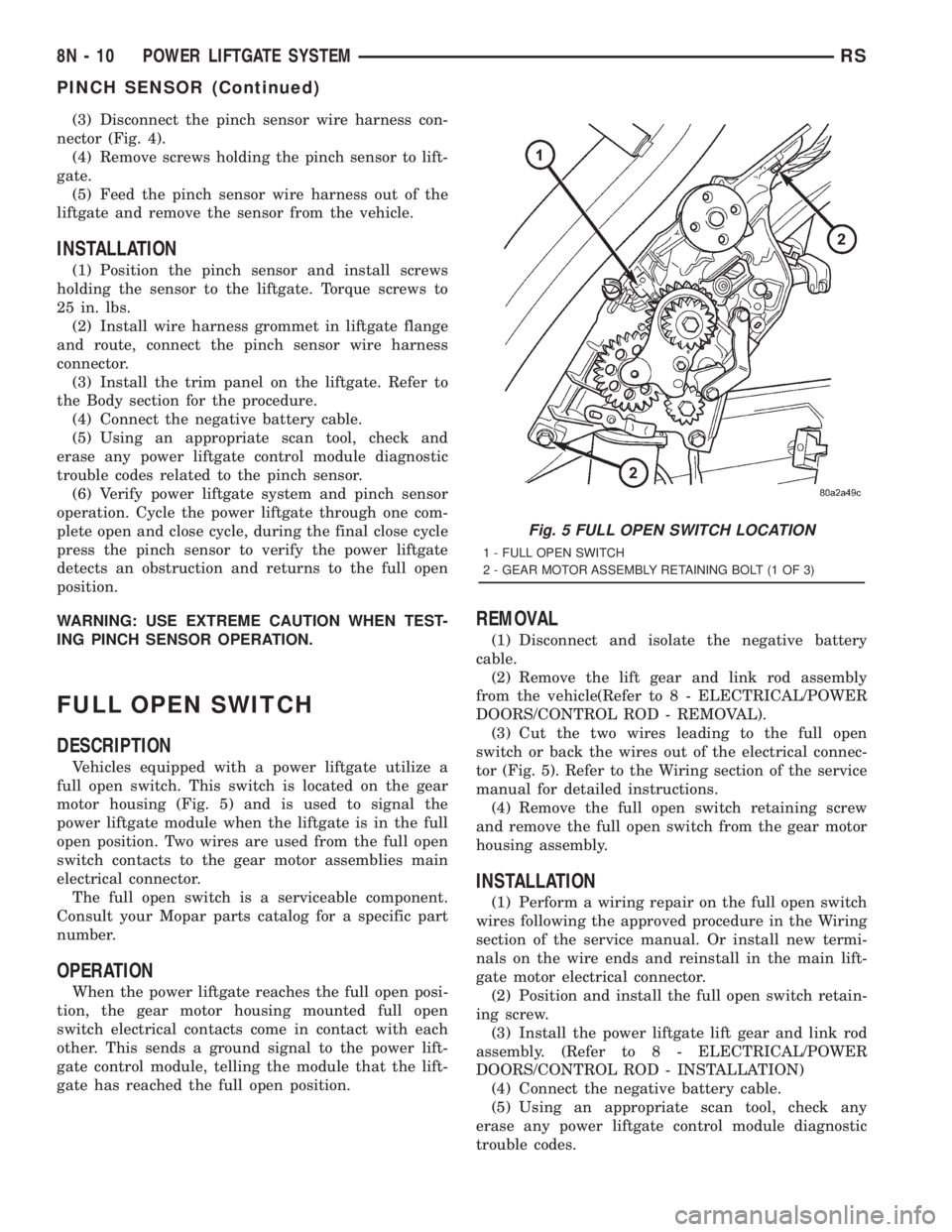
full open switch. This switch is located on the gear
motor housing (Fig. 5) and is used to signal the
power liftgate module when the liftgate is in the full
open position. Two wires are used from the full open
switch contacts to the gear motor assemblies main
electrical connector.
The full open switch is a serviceable component.
Consult your Mopar parts catalog for a specific part
number.
OPERATION
When the power liftgate reaches the full open posi-
tion, the gear motor housing mounted full open
switch electrical contacts come in contact with each
other. This sends a ground signal to the power lift-
gate control module, telling the module that the lift-
gate has reached the full open position.
REMOVAL
(1) Disconnect and isolate the negative battery
cable.
(2) Remove the lift gear and link rod assembly
from the vehicle(Refer to 8 - ELECTRICAL/POWER
DOORS/CONTROL ROD - REMOVAL).
(3) Cut the two wires leading to the full open
switch or back the wires out of the electrical connec-
tor (Fig. 5). Refer to the Wiring section of the service
manual for detailed instructions.
(4) Remove the full open switch retaining screw
and remove the full open switch from the gear motor
housing assembly.
INSTALLATION
(1) Perform a wiring repair on the full open switch
wires following the approved procedure in the Wiring
section of the service manual. Or install new termi-
nals on the wire ends and reinstall in the main lift-
gate motor electrical connector.
(2) Position and install the full open switch retain-
ing screw.
(3) Install the power liftgate lift gear and link rod
assembly. (Refer to 8 - ELECTRICAL/POWER
DOORS/CONTROL ROD - INSTALLATION)
(4) Connect the negative battery cable.
(5) Using an appropriate scan tool, check any
erase any power liftgate control module diagnostic
trouble codes.
Fig. 5 FULL OPEN SWITCH LOCATION
1 - FULL OPEN SWITCH
2 - GEAR MOTOR ASSEMBLY RETAINING BOLT (1 OF 3)
8N - 10 POWER LIFTGATE SYSTEMRS
PINCH SENSOR (Continued)
Page 1991 of 4284
(6) Verify power liftgate system and full open
switch operation. Cycle the power liftgate through
one complete open and close cycle, this will allow the
power liftgate control module to relearn its cycle with
the new components.
LIFTGATE MOTOR
DESCRIPTION
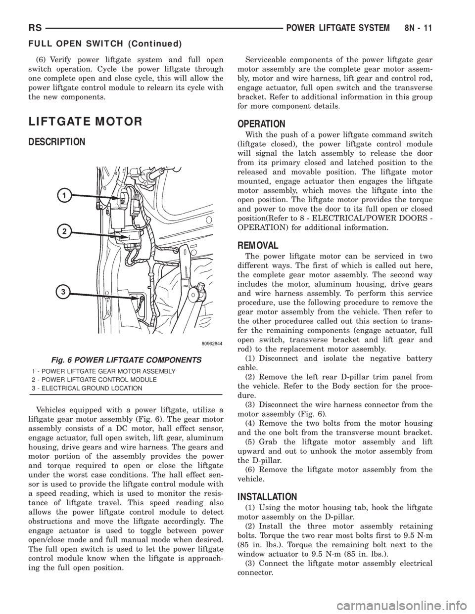
Vehicles equipped with a power liftgate, utilize a
liftgate gear motor assembly (Fig. 6). The gear motor
assembly consists of a DC motor, hall effect sensor,
engage actuator, full open switch, lift gear, aluminum
housing, drive gears and wire harness. The gears and
motor portion of the assembly provides the power
and torque required to open or close the liftgate
under the worst case conditions. The hall effect sen-
sor is used to provide the liftgate control module with
a speed reading, which is used to monitor the resis-
tance of liftgate travel. This speed reading also
allows the power liftgate control module to detect
obstructions and move the liftgate accordingly. The
engage actuator is used to toggle between power
open/close mode and full manual mode when desired.
The full open switch is used to let the power liftgate
control module know when the liftgate is approach-
ing the full open position.Serviceable components of the power liftgate gear
motor assembly are the complete gear motor assem-
bly, motor and wire harness, lift gear and control rod,
engage actuator, full open switch and the transverse
bracket. Refer to additional information in this group
for more component details.
OPERATION
With the push of a power liftgate command switch
(liftgate closed), the power liftgate control module
will signal the latch assembly to release the door
from its primary closed and latched position to the
released and movable position. The liftgate motor
mounted, engage actuator then engages the liftgate
motor assembly, which moves the liftgate into the
open position. The liftgate motor provides the torque
and power to move the door to its full open or closed
position(Refer to 8 - ELECTRICAL/POWER DOORS -
OPERATION) for additional information.
REMOVAL
The power liftgate motor can be serviced in two
different ways. The first of which is called out here,
the complete gear motor assembly. The second way
includes the motor, aluminum housing, drive gears
and wire harness assembly. To perform this service
procedure, use the following procedure to remove the
gear motor assembly from the vehicle. Then refer to
the other procedures called out this section to trans-
fer the remaining components (engage actuator, full
open switch, transverse bracket and lift gear and
rod) to the replacement motor assembly.
(1) Disconnect and isolate the negative battery
cable.
(2) Remove the left rear D-pillar trim panel from
the vehicle. Refer to the Body section for the proce-
dure.
(3) Disconnect the wire harness connector from the
motor assembly (Fig. 6).
(4) Remove the two bolts from the motor housing
and the one bolt from the transverse mount bracket.
(5) Grab the liftgate motor assembly and lift
upward and out to unhook the motor assembly from
the D-pillar.
(6) Remove the liftgate motor assembly from the
vehicle.
INSTALLATION
(1) Using the motor housing tab, hook the liftgate
motor assembly on the D-pillar.
(2) Install the three motor assembly retaining
bolts. Torque the two rear most bolts first to 9.5 N´m
(85 in. lbs.). Torque the remaining bolt next to the
window actuator to 9.5 N´m (85 in. lbs.).
(3) Connect the liftgate motor assembly electrical
connector.
Fig. 6 POWER LIFTGATE COMPONENTS
1 - POWER LIFTGATE GEAR MOTOR ASSEMBLY
2 - POWER LIFTGATE CONTROL MODULE
3 - ELECTRICAL GROUND LOCATION
RSPOWER LIFTGATE SYSTEM8N-11
FULL OPEN SWITCH (Continued)
Page 1993 of 4284
(4) Install the left rear D-pillar trim on the vehi-
cle. Refer to Body for the procedure.
(5) Connect the negative battery cable.
(6) Using an appropriate scan tool, check and
erase any power liftgate control module diagnostic
trouble codes.
(7) Verify power liftgate system and engage actua-
tor operation. Cycle the power liftgate through one
complete open and close cycle.
TRANSVERSE BRACKET
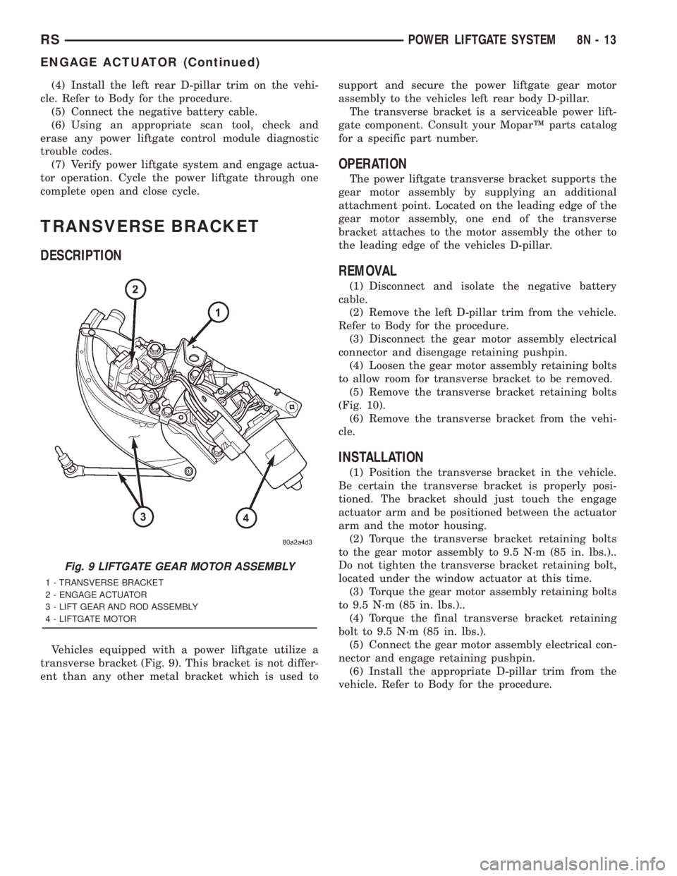
DESCRIPTION
Vehicles equipped with a power liftgate utilize a
transverse bracket (Fig. 9). This bracket is not differ-
ent than any other metal bracket which is used tosupport and secure the power liftgate gear motor
assembly to the vehicles left rear body D-pillar.
The transverse bracket is a serviceable power lift-
gate component. Consult your MoparŸ parts catalog
for a specific part number.
OPERATION
The power liftgate transverse bracket supports the
gear motor assembly by supplying an additional
attachment point. Located on the leading edge of the
gear motor assembly, one end of the transverse
bracket attaches to the motor assembly the other to
the leading edge of the vehicles D-pillar.
REMOVAL
(1) Disconnect and isolate the negative battery
cable.
(2) Remove the left D-pillar trim from the vehicle.
Refer to Body for the procedure.
(3) Disconnect the gear motor assembly electrical
connector and disengage retaining pushpin.
(4) Loosen the gear motor assembly retaining bolts
to allow room for transverse bracket to be removed.
(5) Remove the transverse bracket retaining bolts
(Fig. 10).
(6) Remove the transverse bracket from the vehi-
cle.
INSTALLATION
(1) Position the transverse bracket in the vehicle.
Be certain the transverse bracket is properly posi-
tioned. The bracket should just touch the engage
actuator arm and be positioned between the actuator
arm and the motor housing.
(2) Torque the transverse bracket retaining bolts
to the gear motor assembly to 9.5 N´m (85 in. lbs.)..
Do not tighten the transverse bracket retaining bolt,
located under the window actuator at this time.
(3) Torque the gear motor assembly retaining bolts
to 9.5 N´m (85 in. lbs.)..
(4) Torque the final transverse bracket retaining
bolt to 9.5 N´m (85 in. lbs.).
(5) Connect the gear motor assembly electrical con-
nector and engage retaining pushpin.
(6) Install the appropriate D-pillar trim from the
vehicle. Refer to Body for the procedure.
Fig. 9 LIFTGATE GEAR MOTOR ASSEMBLY
1 - TRANSVERSE BRACKET
2 - ENGAGE ACTUATOR
3 - LIFT GEAR AND ROD ASSEMBLY
4 - LIFTGATE MOTOR
RSPOWER LIFTGATE SYSTEM8N-13
ENGAGE ACTUATOR (Continued)
Page 1994 of 4284
LIFT GEAR & LINK ROD
DESCRIPTION
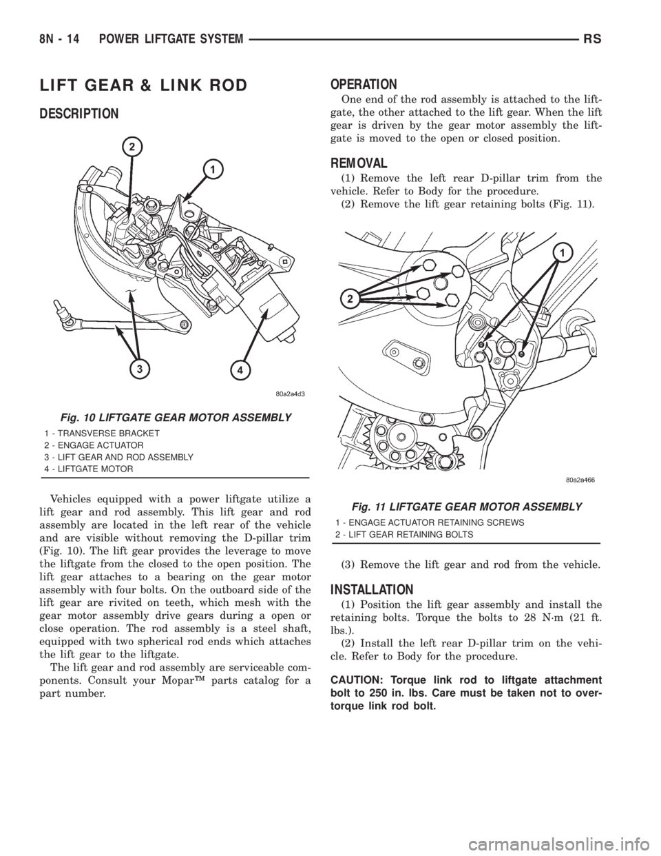
Vehicles equipped with a power liftgate utilize a
lift gear and rod assembly. This lift gear and rod
assembly are located in the left rear of the vehicle
and are visible without removing the D-pillar trim
(Fig. 10). The lift gear provides the leverage to move
the liftgate from the closed to the open position. The
lift gear attaches to a bearing on the gear motor
assembly with four bolts. On the outboard side of the
lift gear are rivited on teeth, which mesh with the
gear motor assembly drive gears during a open or
close operation. The rod assembly is a steel shaft,
equipped with two spherical rod ends which attaches
the lift gear to the liftgate.
The lift gear and rod assembly are serviceable com-
ponents. Consult your MoparŸ parts catalog for a
part number.
OPERATION
One end of the rod assembly is attached to the lift-
gate, the other attached to the lift gear. When the lift
gear is driven by the gear motor assembly the lift-
gate is moved to the open or closed position.
REMOVAL
(1) Remove the left rear D-pillar trim from the
vehicle. Refer to Body for the procedure.
(2) Remove the lift gear retaining bolts (Fig. 11).
(3) Remove the lift gear and rod from the vehicle.
INSTALLATION
(1) Position the lift gear assembly and install the
retaining bolts. Torque the bolts to 28 N´m (21 ft.
lbs.).
(2) Install the left rear D-pillar trim on the vehi-
cle. Refer to Body for the procedure.
CAUTION: Torque link rod to liftgate attachment
bolt to 250 in. lbs. Care must be taken not to over-
torque link rod bolt.
Fig. 10 LIFTGATE GEAR MOTOR ASSEMBLY
1 - TRANSVERSE BRACKET
2 - ENGAGE ACTUATOR
3 - LIFT GEAR AND ROD ASSEMBLY
4 - LIFTGATE MOTOR
Fig. 11 LIFTGATE GEAR MOTOR ASSEMBLY
1 - ENGAGE ACTUATOR RETAINING SCREWS
2 - LIFT GEAR RETAINING BOLTS
8N - 14 POWER LIFTGATE SYSTEMRS
Page 1995 of 4284
LATCH
DESCRIPTION
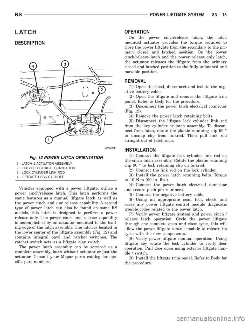
Vehicles equipped with a power liftgate, utilize a
power cinch/release latch. This latch performs the
same features as a manual liftgate latch as well as
the power cinch and / or release capability. A second
type of power latch can also be found on some RS
models, this latch is designed to perform a power
release only. The power cinch and release capability
is accomplished by an actuator mounted to the lead-
ing edge of the latch assembly. The latch is located in
the lower center of the liftgate assembly (Fig. 12) and
contains integral pawl and ratchet switches. The
ratchet switch acts as a liftgate ajar switch.
The power latch assembly can be serviced as a
complete assembly, latch without actuator or just the
actuator. Consult your Mopar parts catalog for spe-
cific part numbers.
OPERATION
On the power cinch/release latch, the latch
mounted actuator provides the torque required to
close the power liftgate from the secondary to the pri-
mary closed and latched position. On the power
cinch/release latch and the power release only latch,
the actuator releases the liftgate from the primary
closed and latched position to the fully unlatched and
movable position.
REMOVAL
(1) Open the hood, disconnect and isolate the neg-
ative battery cable.
(2) Open the liftgate and remove the liftgate trim
panel. Refer to Body for the procedure.
(3) Disconnect the power latch electrical connector
(Fig. 12).
(4) Remove the power latch retaining bolts.
(5) Disconnect the liftgate lock cylinder link rod
from the key cylinder or latch assembly. To discon-
nect from latch, rotate the plastic retaining clip 90 É
to unsnap clip from linkrod. Then pull link rod
straight out of latch arm.
INSTALLATION
(1) Connect the liftgate lock cylinder link rod on
the cinch latch assembly. Rotate the plastic retaining
clip 90 É to lock retaining clip on linkrod.
(2) Connect the link rod on the lock cylinder.
(3) Install the power latch retaining bolts. Torque
to 10 N´m (90 in. lbs.).
(4) Connect the power latch electrical connector
and secure push pin retainers.
(5) Connect the negative battery cable.
(6) Using an appropriate scan tool, check and
erase any power liftgate control module diagnostic
trouble codes related to the power latch.
(7) Verify power liftgate system and power cinch /
release latch operation. Cycle the power liftgate
through one complete open and close cycle, this will
allow the power liftgate control module to relearn its
cycle with the new components.
(8) Verify power liftgate manual operation. Using
liftgate key rotate the lock cylinder to verify door
operation. Pull door open using exterior liftgate han-
dle / switch.
(9) Install the liftgate trim panel. Refer to Body for
the procedure.Fig. 12 POWER LATCH ORIENTATION
1 - LATCH & ACTUATOR ASSEMBLY
2 - LATCH ELECTRICAL CONNECTOR
3 - LOCK CYLINDER LINK ROD
4 - LIFTGATE LOCK CYLINDER
RSPOWER LIFTGATE SYSTEM8N-15
Page 1996 of 4284
LATCH ACTUATOR
DESCRIPTION
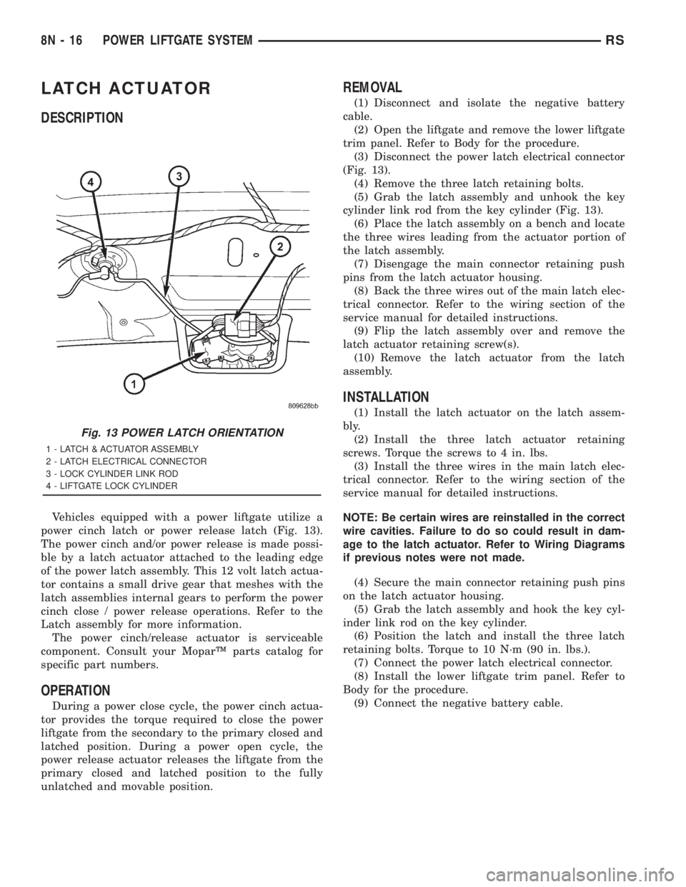
Vehicles equipped with a power liftgate utilize a
power cinch latch or power release latch (Fig. 13).
The power cinch and/or power release is made possi-
ble by a latch actuator attached to the leading edge
of the power latch assembly. This 12 volt latch actua-
tor contains a small drive gear that meshes with the
latch assemblies internal gears to perform the power
cinch close / power release operations. Refer to the
Latch assembly for more information.
The power cinch/release actuator is serviceable
component. Consult your MoparŸ parts catalog for
specific part numbers.
OPERATION
During a power close cycle, the power cinch actua-
tor provides the torque required to close the power
liftgate from the secondary to the primary closed and
latched position. During a power open cycle, the
power release actuator releases the liftgate from the
primary closed and latched position to the fully
unlatched and movable position.
REMOVAL
(1) Disconnect and isolate the negative battery
cable.
(2) Open the liftgate and remove the lower liftgate
trim panel. Refer to Body for the procedure.
(3) Disconnect the power latch electrical connector
(Fig. 13).
(4) Remove the three latch retaining bolts.
(5) Grab the latch assembly and unhook the key
cylinder link rod from the key cylinder (Fig. 13).
(6) Place the latch assembly on a bench and locate
the three wires leading from the actuator portion of
the latch assembly.
(7) Disengage the main connector retaining push
pins from the latch actuator housing.
(8) Back the three wires out of the main latch elec-
trical connector. Refer to the wiring section of the
service manual for detailed instructions.
(9) Flip the latch assembly over and remove the
latch actuator retaining screw(s).
(10) Remove the latch actuator from the latch
assembly.
INSTALLATION
(1) Install the latch actuator on the latch assem-
bly.
(2) Install the three latch actuator retaining
screws. Torque the screws to 4 in. lbs.
(3) Install the three wires in the main latch elec-
trical connector. Refer to the wiring section of the
service manual for detailed instructions.
NOTE: Be certain wires are reinstalled in the correct
wire cavities. Failure to do so could result in dam-
age to the latch actuator. Refer to Wiring Diagrams
if previous notes were not made.
(4) Secure the main connector retaining push pins
on the latch actuator housing.
(5) Grab the latch assembly and hook the key cyl-
inder link rod on the key cylinder.
(6) Position the latch and install the three latch
retaining bolts. Torque to 10 N´m (90 in. lbs.).
(7) Connect the power latch electrical connector.
(8) Install the lower liftgate trim panel. Refer to
Body for the procedure.
(9) Connect the negative battery cable.
Fig. 13 POWER LATCH ORIENTATION
1 - LATCH & ACTUATOR ASSEMBLY
2 - LATCH ELECTRICAL CONNECTOR
3 - LOCK CYLINDER LINK ROD
4 - LIFTGATE LOCK CYLINDER
8N - 16 POWER LIFTGATE SYSTEMRS