2001 CHRYSLER VOYAGER torque
[x] Cancel search: torquePage 1709 of 4284
(6) If the vehicle is equipped with speed control,
disconnect the vacuum hose at the vacuum tank built
into the battery tray.
(7) Remove the two nuts and one bolt securing bat-
tery tray in place. Remove battery tray.
(8) If vehicle is equipped with speed control:
(a) Disconnect wiring harness connector from
the speed control servo.
(b) Remove the two servo mounting nuts.
(c) Lay speed control servo off to the side, out of
the way.
(9) If the vehicle is equipped with the 2.5L diesel
engine, remove the coolant recovery pressure con-
tainer and bracket. (Refer to 7 - COOLING/ENGINE/
COOLANT RECOVERY PRESS CONTAINER -
REMOVAL)
(10) Disconnect wiring harness connector from
brake fluid level switch in master cylinder fluid res-
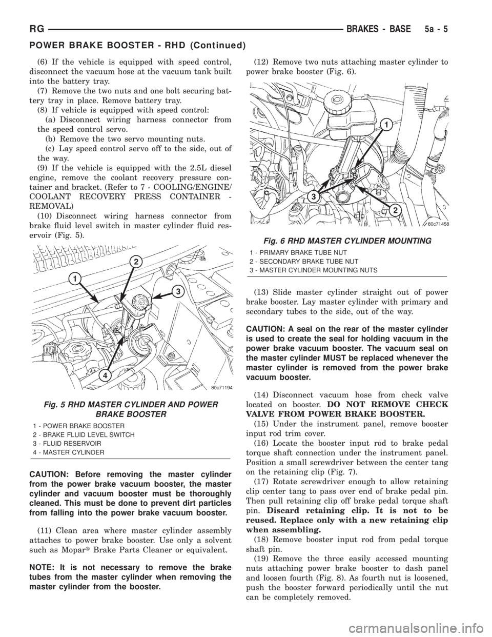
ervoir (Fig. 5).
CAUTION: Before removing the master cylinder
from the power brake vacuum booster, the master
cylinder and vacuum booster must be thoroughly
cleaned. This must be done to prevent dirt particles
from falling into the power brake vacuum booster.
(11) Clean area where master cylinder assembly
attaches to power brake booster. Use only a solvent
such as MopartBrake Parts Cleaner or equivalent.
NOTE: It is not necessary to remove the brake
tubes from the master cylinder when removing the
master cylinder from the booster.(12) Remove two nuts attaching master cylinder to
power brake booster (Fig. 6).
(13) Slide master cylinder straight out of power
brake booster. Lay master cylinder with primary and
secondary tubes to the side, out of the way.
CAUTION: A seal on the rear of the master cylinder
is used to create the seal for holding vacuum in the
power brake vacuum booster. The vacuum seal on
the master cylinder MUST be replaced whenever the
master cylinder is removed from the power brake
vacuum booster.
(14) Disconnect vacuum hose from check valve
located on booster.DO NOT REMOVE CHECK
VALVE FROM POWER BRAKE BOOSTER.
(15) Under the instrument panel, remove booster
input rod trim cover.
(16) Locate the booster input rod to brake pedal
torque shaft connection under the instrument panel.
Position a small screwdriver between the center tang
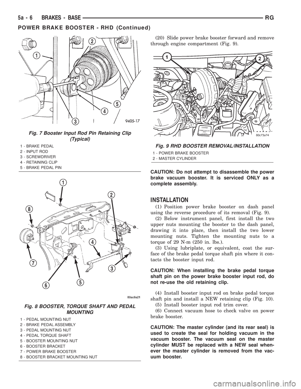
on the retaining clip (Fig. 7).
(17) Rotate screwdriver enough to allow retaining
clip center tang to pass over end of brake pedal pin.
Then pull retaining clip off brake pedal torque shaft
pin.Discard retaining clip. It is not to be
reused. Replace only with a new retaining clip
when assembling.
(18) Remove booster input rod from pedal torque
shaft pin.
(19) Remove the three easily accessed mounting
nuts attaching power brake booster to dash panel
and loosen fourth (Fig. 8). As fourth nut is loosened,
push the booster forward periodically until the nut
can be completely removed.
Fig. 5 RHD MASTER CYLINDER AND POWER
BRAKE BOOSTER
1 - POWER BRAKE BOOSTER
2 - BRAKE FLUID LEVEL SWITCH
3 - FLUID RESERVOIR
4 - MASTER CYLINDER
Fig. 6 RHD MASTER CYLINDER MOUNTING
1 - PRIMARY BRAKE TUBE NUT
2 - SECONDARY BRAKE TUBE NUT
3 - MASTER CYLINDER MOUNTING NUTS
RGBRAKES - BASE5a-5
POWER BRAKE BOOSTER - RHD (Continued)
Page 1710 of 4284
(20) Slide power brake booster forward and remove
through engine compartment (Fig. 9).
CAUTION: Do not attempt to disassemble the power
brake vacuum booster. It is serviced ONLY as a
complete assembly.
INSTALLATION
(1) Position power brake booster on dash panel
using the reverse procedure of its removal (Fig. 9).
(2) Below instrument panel, first install the two
upper nuts mounting the booster to the dash panel,
drawing it into place, then install the two lower
mounting nuts. Tighten the mounting nuts to a
torque of 29 N´m (250 in. lbs.).
(3) Using lubriplate, or equivalent, coat the sur-
face of the brake pedal torque shaft pin where it con-
tacts the booster input rod.
CAUTION: When installing the brake pedal torque
shaft pin on the power brake booster input rod, do
not re-use the old retaining clip.
(4) Install booster input rod on brake pedal torque
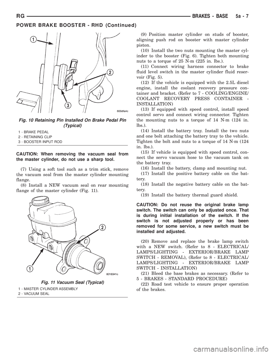
shaft pin and install a NEW retaining clip (Fig. 10).
(5) Install booster input rod trim cover.
(6) Connect vacuum hose to check valve on power
brake booster.
CAUTION: The master cylinder (and its rear seal) is
used to create the seal for holding vacuum in the
vacuum booster. The vacuum seal on the master
cylinder MUST be replaced with a NEW seal when-
ever the master cylinder is removed from the vac-
uum booster.
Fig. 7 Booster Input Rod Pin Retaining Clip
(Typical)
1 - BRAKE PEDAL
2 - INPUT ROD
3 - SCREWDRIVER
4 - RETAINING CLIP
5 - BRAKE PEDAL PIN
Fig. 8 BOOSTER, TORQUE SHAFT AND PEDAL
MOUNTING
1 - PEDAL MOUNTING NUT
2 - BRAKE PEDAL ASSEMBLY
3 - PEDAL MOUNTING NUT
4 - PEDAL TORQUE SHAFT
5 - BOOSTER MOUNTING NUT
6 - BOOSTER BRACKET
7 - POWER BRAKE BOOSTER
8 - BOOSTER BRACKET MOUNTING NUT
Fig. 9 RHD BOOSTER REMOVAL/INSTALLATION
1 - POWER BRAKE BOOSTER
2 - MASTER CYLINDER
5a - 6 BRAKES - BASERG
POWER BRAKE BOOSTER - RHD (Continued)
Page 1711 of 4284
CAUTION: When removing the vacuum seal from
the master cylinder, do not use a sharp tool.
(7) Using a soft tool such as a trim stick, remove
the vacuum seal from the master cylinder mounting
flange.
(8) Install a NEW vacuum seal on rear mounting
flange of the master cylinder (Fig. 11).(9) Position master cylinder on studs of booster,
aligning push rod on booster with master cylinder
piston.
(10) Install the two nuts mounting the master cyl-
inder to the booster (Fig. 6). Tighten both mounting
nuts to a torque of 25 N´m (225 in. lbs.).
(11) Connect wiring harness connector to brake
fluid level switch in the master cylinder fluid reser-
voir (Fig. 5).
(12) If the vehicle is equipped with the 2.5L diesel
engine, install the coolant recovery pressure con-
tainer and bracket. (Refer to 7 - COOLING/ENGINE/
COOLANT RECOVERY PRESS CONTAINER -
INSTALLATION)
(13) If equipped with speed control, install speed
control servo and connect wiring connector. Tighten
the mounting nuts to a torque of 14 N´m (124 in.
lbs.).
(14) Install the battery tray. Install the two nuts
and one bolt attaching the battery tray to the vehicle.
Tighten the bolt and nuts to a torque of 14 N´m (124
in. lbs.).
(15) If vehicle is equipped with speed control, con-
nect the servo vacuum hose to the vacuum tank on
the battery tray.
(16) Install the battery, clamp and mounting nut.
(17) Install the positive battery cable on the bat-
tery.
(18) Install the negative battery cable on the bat-
tery.
(19) Install the battery thermal guard shield.
CAUTION: Do not reuse the original brake lamp
switch. The switch can only be adjusted once. That
is during initial installation of the switch. If the
switch is not adjusted properly or has been
removed for some service, a new switch must be
installed and adjusted.
(20) Remove and replace the brake lamp switch
with a NEW switch. (Refer to 8 - ELECTRICAL/
LAMPS/LIGHTING - EXTERIOR/BRAKE LAMP
SWITCH - REMOVAL), (Refer to 8 - ELECTRICAL/
LAMPS/LIGHTING - EXTERIOR/BRAKE LAMP
SWITCH - INSTALLATION)
(21) Bleed the base brakes as necessary. (Refer to
5 - BRAKES - STANDARD PROCEDURE)
(22) Road test vehicle to ensure proper operation
of the brakes.
Fig. 10 Retaining Pin Installed On Brake Pedal Pin
(Typical)
1 - BRAKE PEDAL
2 - RETAINING CLIP
3 - BOOSTER INPUT ROD
Fig. 11 Vacuum Seal (Typical)
1 - MASTER CYLINDER ASSEMBLY
2 - VACUUM SEAL
RGBRAKES - BASE5a-7
POWER BRAKE BOOSTER - RHD (Continued)
Page 1716 of 4284
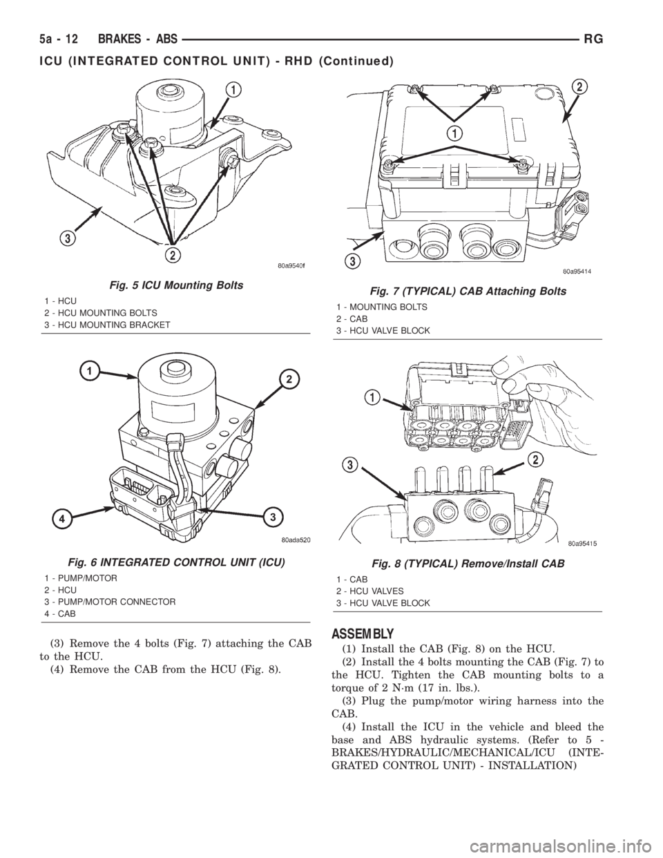
(3) Remove the 4 bolts (Fig. 7) attaching the CAB
to the HCU.
(4) Remove the CAB from the HCU (Fig. 8).ASSEMBLY
(1) Install the CAB (Fig. 8) on the HCU.
(2) Install the 4 bolts mounting the CAB (Fig. 7) to
the HCU. Tighten the CAB mounting bolts to a
torque of 2 N´m (17 in. lbs.).
(3) Plug the pump/motor wiring harness into the
CAB.
(4) Install the ICU in the vehicle and bleed the
base and ABS hydraulic systems. (Refer to 5 -
BRAKES/HYDRAULIC/MECHANICAL/ICU (INTE-
GRATED CONTROL UNIT) - INSTALLATION)
Fig. 5 ICU Mounting Bolts
1 - HCU
2 - HCU MOUNTING BOLTS
3 - HCU MOUNTING BRACKET
Fig. 6 INTEGRATED CONTROL UNIT (ICU)
1 - PUMP/MOTOR
2 - HCU
3 - PUMP/MOTOR CONNECTOR
4 - CAB
Fig. 7 (TYPICAL) CAB Attaching Bolts
1 - MOUNTING BOLTS
2 - CAB
3 - HCU VALVE BLOCK
Fig. 8 (TYPICAL) Remove/Install CAB
1 - CAB
2 - HCU VALVES
3 - HCU VALVE BLOCK
5a - 12 BRAKES - ABSRG
ICU (INTEGRATED CONTROL UNIT) - RHD (Continued)
Page 1717 of 4284
INSTALLATION - RHD
(1) Install the ICU on the mounting bracket (Fig.
5). Install the 3 bolts (Fig. 5) attaching the ICU to
the mounting bracket. Tighten the 3 mounting bolts
to a torque of 11 N´m (97 in. lbs.).
CAUTION: The ICU mounting bracket to front sus-
pension cradle mounting bolts have a unique corro-
sion protection coating and a special aluminum
washer. For this reason, only the original, or origi-
nal equipment Mopar replacement bolts can be
used to mount the ICU bracket to the front suspen-
sion crossmember.
(2) Install the ICU and its mounting bracket as an
assembly on the front suspension crossmember.
Install the 3 bolts attaching the ICU bracket to the
crossmember (Fig. 4). Tighten the 3 mounting bolts
to a torque of 28 N´m (250 in. lbs.).
CAUTION: Because of the flexible section in the pri-
mary and secondary brake tubes, and the brake
tubes between the HCU and the proportioning
valve, the brake tubes must be held in proper ori-
entation when tightened and torqued. These tubes
must not contact each other or other vehicle com-
ponents when installed. Also, after the brake tubes
are installed on the HCU, ensure all spacer clips are
reinstalled on the brake tubes.
CAUTION: When installing the chassis brake tubes
on the HCU valve block, they must be located cor-
rectly in the valve block to ensure proper ABS oper-
ation. Refer to (Fig. 3) for the correct chassis brake
tube locations.
NOTE: The chassis brake tube attachment locations
to the HCU, are marked on the bottom of the ICU
mounting bracket.
(3) Install the 6 chassis brake tubes into their cor-
rect port locations on the HCU valve block as shown
in (Fig. 3). Tighten the tube nuts to a torque of 17
N´m (145 in. lbs.).
NOTE: Before installing the 24-way connector in the
CAB be sure the seal is properly installed in the
connector.(4) Install the 24-way connector (Fig. 1) on the
CAB using the following procedure. Position the
24-way connector in the socket of the CAB and care-
fully push it down as far as possible. When connector
is fully seated by hand into the CAB socket, push in
the connector lock (Fig. 2). This will pull the connec-
tor into the socket of the CAB and lock it in the
installed position.
NOTE: The CAB wiring harness must be clipped to
the ICU mounting bracket. This will ensure the wir-
ing harness is properly routed and does not contact
the brake tubes or the body of the vehicle.
(5) Clip the cab wiring harness (Fig. 1) to the ICU
mounting bracket.
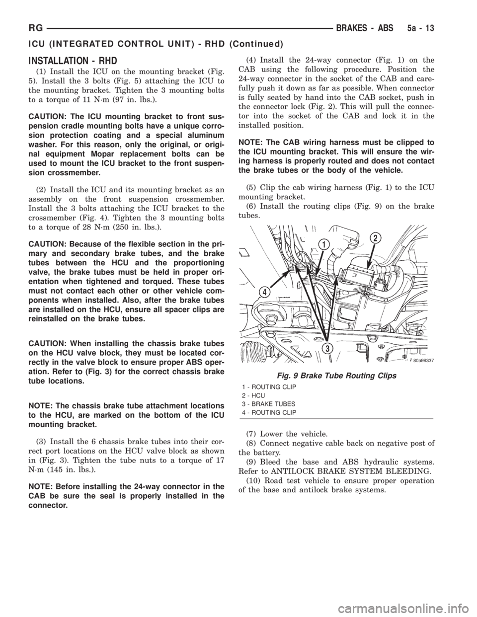
(6) Install the routing clips (Fig. 9) on the brake
tubes.
(7) Lower the vehicle.
(8) Connect negative cable back on negative post of
the battery.
(9) Bleed the base and ABS hydraulic systems.
Refer to ANTILOCK BRAKE SYSTEM BLEEDING.
(10) Road test vehicle to ensure proper operation
of the base and antilock brake systems.
Fig. 9 Brake Tube Routing Clips
1 - ROUTING CLIP
2 - HCU
3 - BRAKE TUBES
4 - ROUTING CLIP
RGBRAKES - ABS5a-13
ICU (INTEGRATED CONTROL UNIT) - RHD (Continued)
Page 1725 of 4284
DIAGNOSIS AND TESTING - DRIVE PLATE
MISALIGNMENT
Common causes of misalignment are:
²Heat warping
²Mounting drive plate on a dirty crankshaft
flange
²Incorrect bolt tightening
²Improper seating on the crankshaft shoulder
²Loose crankshaft bolts
Clean the crankshaft flange before mounting the
drive plate. Dirt and grease on the flange surface
may misalign the flywheel, causing excessive runout.
Use new bolts when mounting drive plate to crank-
shaft. Tighten drive plate bolts to specified torque
only. Over-tightening can distort the drive plate hub
causing excessive runout.
DIAGNOSIS AND TESTING - CLUTCH COVER
AND DISC RUNOUT
Check condition of the clutch cover before installa-
tion. A warped cover or diaphragm spring will cause
grab and/or incomplete release or engagement. Use
care when handling the clutch assembly. Impact can
distort the cover, diaphragm spring, and release fin-
gers.
DIAGNOSIS AND TESTING - CLUTCH CHATTER
COMPLAINTS
For all clutch chatter complaints, perform the fol-
lowing:
(1) Check for loose, misaligned, or broken engine
and transmission mounts. If present, they should be
corrected at this time. Test vehicle for chatter. If
chatter is gone, there is no need to go any further.
(2) If chatter persists, check hydraulic clutch
release system is functioning properly.
(3) Check for loose connections in drivetrain. Cor-
rect any problems and determine if clutch chatter
complaints have been satisfied. If not:
(a) Remove transaxle.
(b) Check to see if the release bearing is sticky
or binding. Replace bearing, if needed.
(c) Check linkage for excessive wear on the pivot
stud and fork fingers. Replace all worn parts.
(d) Check clutch assembly for contamination
(dirt, oil). Replace clutch assembly, if required.
(e) Check to see if the clutch disc hub splines
are damaged. Replace with new clutch assembly, if
necessary.
(f) Check input shaft splines for damage.
Replace, if necessary.
(g) Check for uneven wear on clutch fingers.
(h) Check for broken clutch cover diaphragm
spring fingers. Replace with new clutch assembly,
if necessary.
SPECIAL TOOLS
SPECIAL TOOLS - T850 TRANSAXLE
CLUTCH RELEASE CABLE -
LHD
REMOVAL
(1) Disconnect battery negative cable.
(2) Raise vehicle on hoist.
(3)Diesel models:Remove underbody splash
shield.
(4) Remove clutch bellhousing cap.
(5) Some models will have a clutch cable retainer
clip at the transaxle to secure it to the case (Fig. 9).
If retainer clip is installed, dislodge clip from from
inside bellhousing using a suitable screwdriver (Fig.
10), pull outward on cable conduit, guiding cable core
wire through slot in bellhousing and disengaging
cable ªTº from clutch release lever (Fig. 11). If
retainer is not installed, disengage clutch cable from
transaxle by pulling outward on cable conduit, guid-
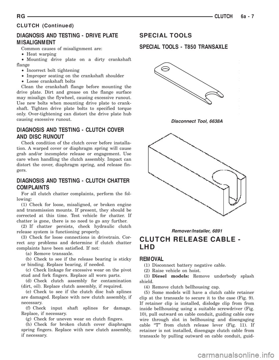
Disconnect Tool, 6638A
Remover/Installer, 6891
RGCLUTCH6a-7
CLUTCH (Continued)
Page 1733 of 4284
INSTALLATION
(1) Install modular clutch assembly to transaxle
input shaft (Fig. 31).
(2) Install transaxle to vehicle. (Refer to 21 -
TRANSMISSION/TRANSAXLE/MANUAL - INSTAL-
LATION)
SLAVE CYLINDER - RHD
REMOVAL
(1) Raise vehicle on hoist.Diesel models:Remove
underbody splash shield.
(2) Using Tool 6638A, disconnect hyrdraulic clutch
circuit quick connect fitting.
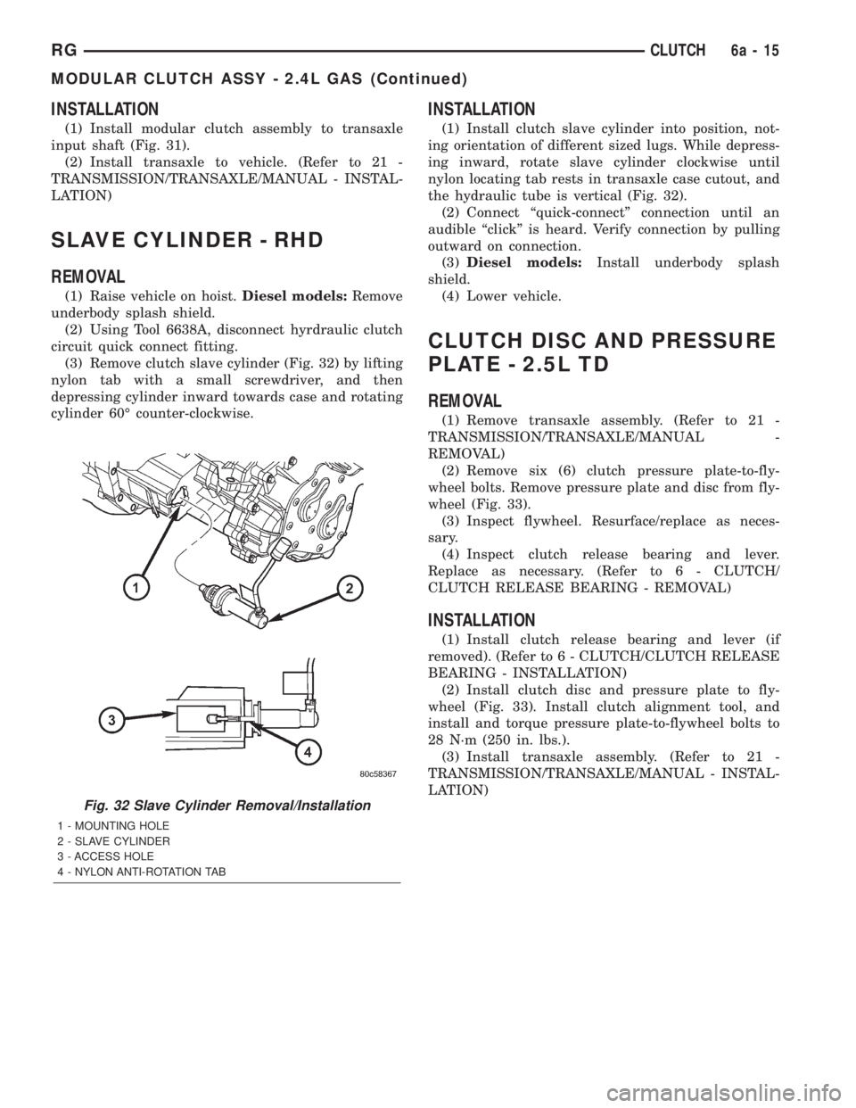
(3) Remove clutch slave cylinder (Fig. 32) by lifting
nylon tab with a small screwdriver, and then
depressing cylinder inward towards case and rotating
cylinder 60É counter-clockwise.
INSTALLATION
(1) Install clutch slave cylinder into position, not-
ing orientation of different sized lugs. While depress-
ing inward, rotate slave cylinder clockwise until
nylon locating tab rests in transaxle case cutout, and
the hydraulic tube is vertical (Fig. 32).
(2) Connect ªquick-connectº connection until an
audible ªclickº is heard. Verify connection by pulling
outward on connection.
(3)Diesel models:Install underbody splash
shield.
(4) Lower vehicle.
CLUTCH DISC AND PRESSURE
PLATE - 2.5L TD
REMOVAL
(1) Remove transaxle assembly. (Refer to 21 -
TRANSMISSION/TRANSAXLE/MANUAL -
REMOVAL)
(2) Remove six (6) clutch pressure plate-to-fly-
wheel bolts. Remove pressure plate and disc from fly-
wheel (Fig. 33).
(3) Inspect flywheel. Resurface/replace as neces-
sary.
(4) Inspect clutch release bearing and lever.
Replace as necessary. (Refer to 6 - CLUTCH/
CLUTCH RELEASE BEARING - REMOVAL)
INSTALLATION
(1) Install clutch release bearing and lever (if
removed). (Refer to 6 - CLUTCH/CLUTCH RELEASE
BEARING - INSTALLATION)
(2) Install clutch disc and pressure plate to fly-
wheel (Fig. 33). Install clutch alignment tool, and
install and torque pressure plate-to-flywheel bolts to
28 N´m (250 in. lbs.).
(3) Install transaxle assembly. (Refer to 21 -
TRANSMISSION/TRANSAXLE/MANUAL - INSTAL-
LATION)
Fig. 32 Slave Cylinder Removal/Installation
1 - MOUNTING HOLE
2 - SLAVE CYLINDER
3 - ACCESS HOLE
4 - NYLON ANTI-ROTATION TAB
RGCLUTCH6a-15
MODULAR CLUTCH ASSY - 2.4L GAS (Continued)
Page 1734 of 4284
FLYWHEEL
REMOVAL
(1) Remove transaxle assembly. (Refer to 21 -
TRANSMISSION/TRANSAXLE/MANUAL -
REMOVAL)
(2) Remove clutch pressure plate and disc. (Refer
to 6 - CLUTCH/CLUTCH DISC - REMOVAL)
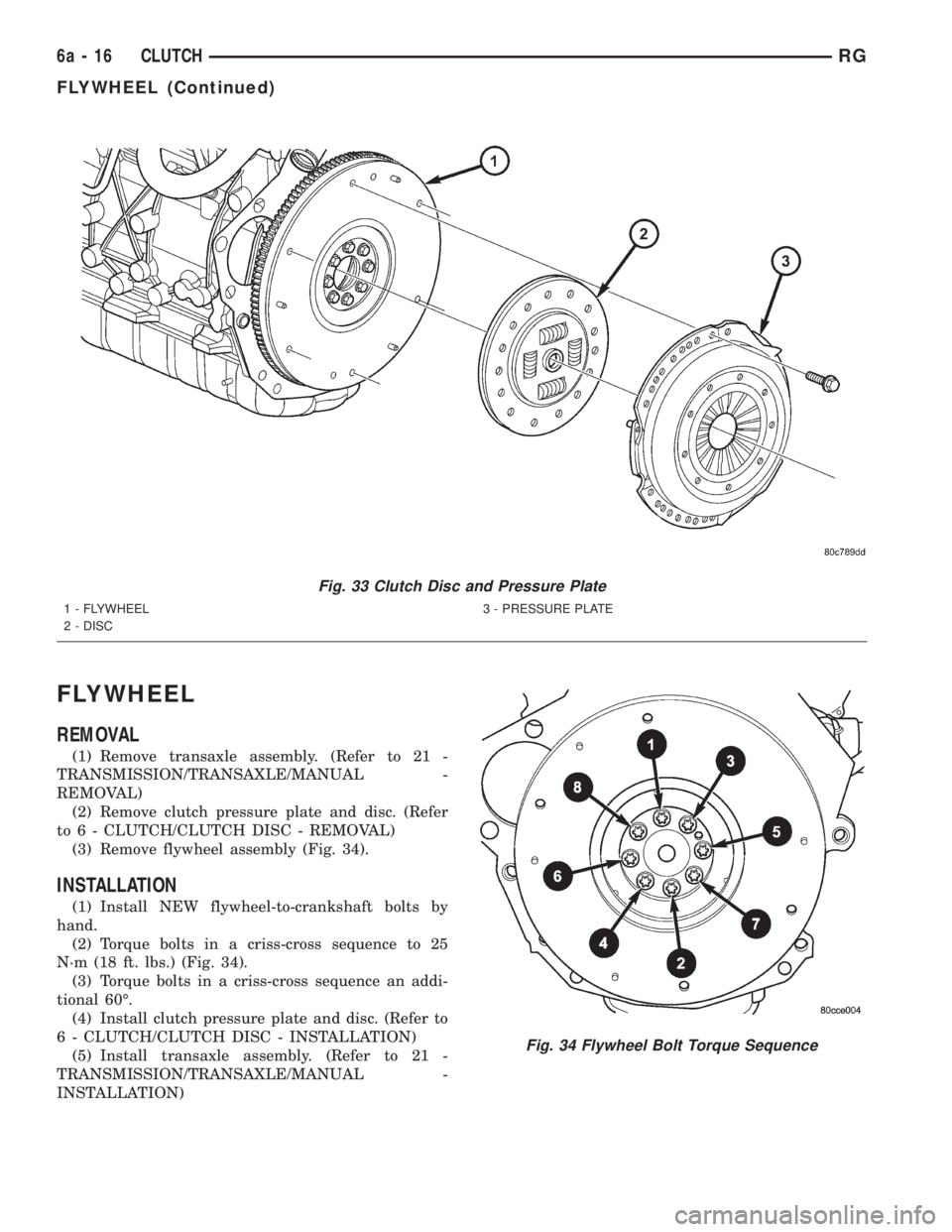
(3) Remove flywheel assembly (Fig. 34).
INSTALLATION
(1) Install NEW flywheel-to-crankshaft bolts by
hand.
(2) Torque bolts in a criss-cross sequence to 25
N´m (18 ft. lbs.) (Fig. 34).
(3) Torque bolts in a criss-cross sequence an addi-
tional 60É.
(4) Install clutch pressure plate and disc. (Refer to
6 - CLUTCH/CLUTCH DISC - INSTALLATION)
(5) Install transaxle assembly. (Refer to 21 -
TRANSMISSION/TRANSAXLE/MANUAL -
INSTALLATION)
Fig. 33 Clutch Disc and Pressure Plate
1 - FLYWHEEL
2 - DISC3 - PRESSURE PLATE
Fig. 34 Flywheel Bolt Torque Sequence
6a - 16 CLUTCHRG
FLYWHEEL (Continued)