2001 CHRYSLER VOYAGER torque
[x] Cancel search: torquePage 1621 of 4284
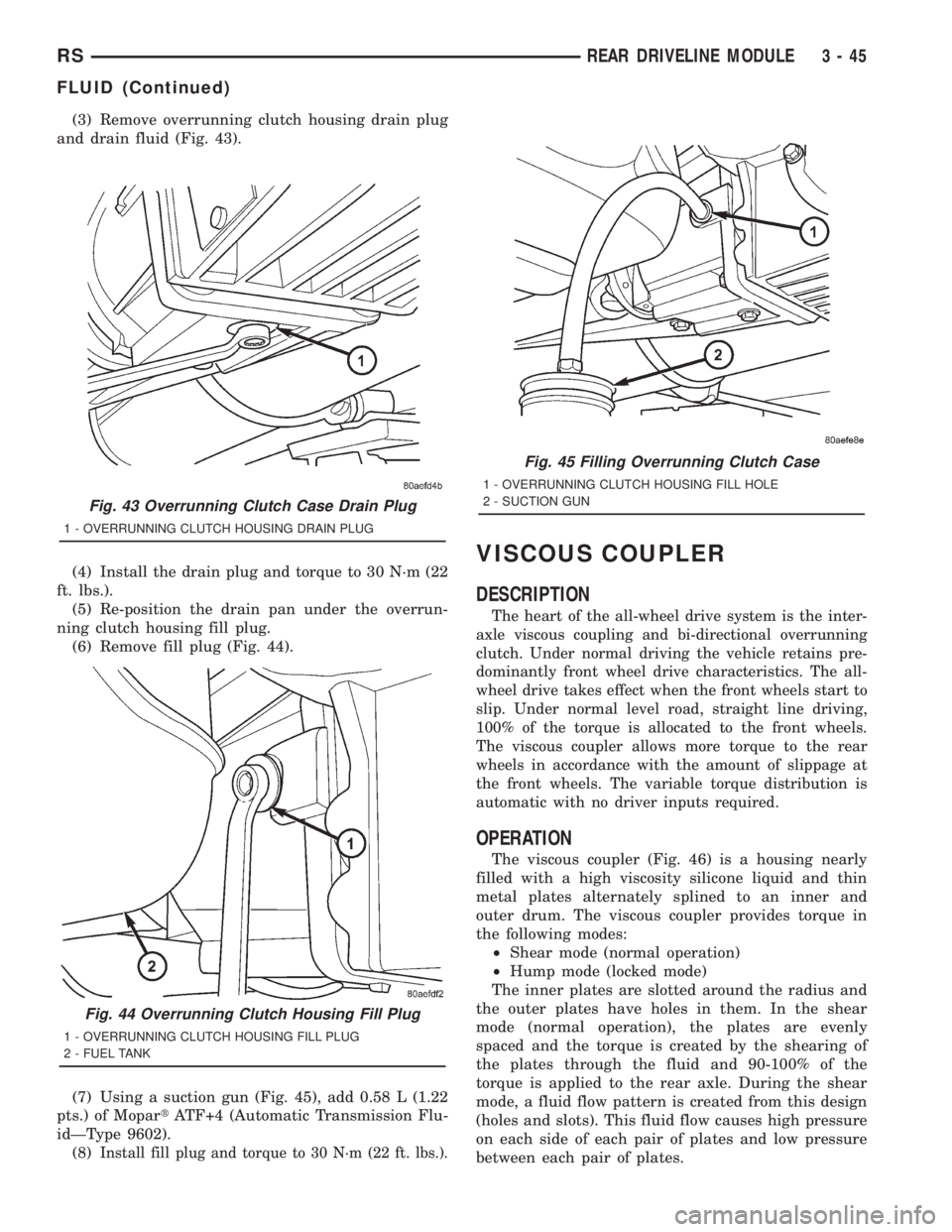
(3) Remove overrunning clutch housing drain plug
and drain fluid (Fig. 43).
(4) Install the drain plug and torque to 30 N´m (22
ft. lbs.).
(5) Re-position the drain pan under the overrun-
ning clutch housing fill plug.
(6) Remove fill plug (Fig. 44).
(7) Using a suction gun (Fig. 45), add 0.58 L (1.22
pts.) of MopartATF+4 (Automatic Transmission Flu-
idÐType 9602).
(8)
Install fill plug and torque to 30 N´m (22 ft. lbs.).
VISCOUS COUPLER
DESCRIPTION
The heart of the all-wheel drive system is the inter-
axle viscous coupling and bi-directional overrunning
clutch. Under normal driving the vehicle retains pre-
dominantly front wheel drive characteristics. The all-
wheel drive takes effect when the front wheels start to
slip. Under normal level road, straight line driving,
100% of the torque is allocated to the front wheels.
The viscous coupler allows more torque to the rear
wheels in accordance with the amount of slippage at
the front wheels. The variable torque distribution is
automatic with no driver inputs required.
OPERATION
The viscous coupler (Fig. 46) is a housing nearly
filled with a high viscosity silicone liquid and thin
metal plates alternately splined to an inner and
outer drum. The viscous coupler provides torque in
the following modes:
²Shear mode (normal operation)
²Hump mode (locked mode)
The inner plates are slotted around the radius and
the outer plates have holes in them. In the shear
mode (normal operation), the plates are evenly
spaced and the torque is created by the shearing of
the plates through the fluid and 90-100% of the
torque is applied to the rear axle. During the shear
mode, a fluid flow pattern is created from this design
(holes and slots). This fluid flow causes high pressure
on each side of each pair of plates and low pressure
between each pair of plates.
Fig. 43 Overrunning Clutch Case Drain Plug
1 - OVERRUNNING CLUTCH HOUSING DRAIN PLUG
Fig. 44 Overrunning Clutch Housing Fill Plug
1 - OVERRUNNING CLUTCH HOUSING FILL PLUG
2 - FUEL TANK
Fig. 45 Filling Overrunning Clutch Case
1 - OVERRUNNING CLUTCH HOUSING FILL HOLE
2 - SUCTION GUN
RSREAR DRIVELINE MODULE3-45
FLUID (Continued)
Page 1623 of 4284
When a high speed difference (shear) occurs
because of loss of traction (one axle spinning faster
than the other), the silicone fluid expands as it heats
from this shearing. When the silicone expands to fill
the viscous coupler completely, this pressure differ-
ence is high enough to squeeze each pair of plates
together. The resulting hump torque is up to 8 times
higher than the shear torque. When the viscous cou-
pler is in the hump mode, it does not lock the axles
(undifferentiated 4-Wheel Drive). It controls the
amount of slippage while delivering maximum power
to the axle having greatest traction. Once the speed
difference equalizes the fluid and plates cool down
and the viscous coupler goes back to the shear mode.
TORQUE ARM
REMOVAL
(1) Raise vehicle on hoist.
(2) Remove rear driveline module assembly. (Refer
to 3 - DIFFERENTIAL & DRIVELINE/REAR DRIV-
ELINE MODULE - REMOVAL)
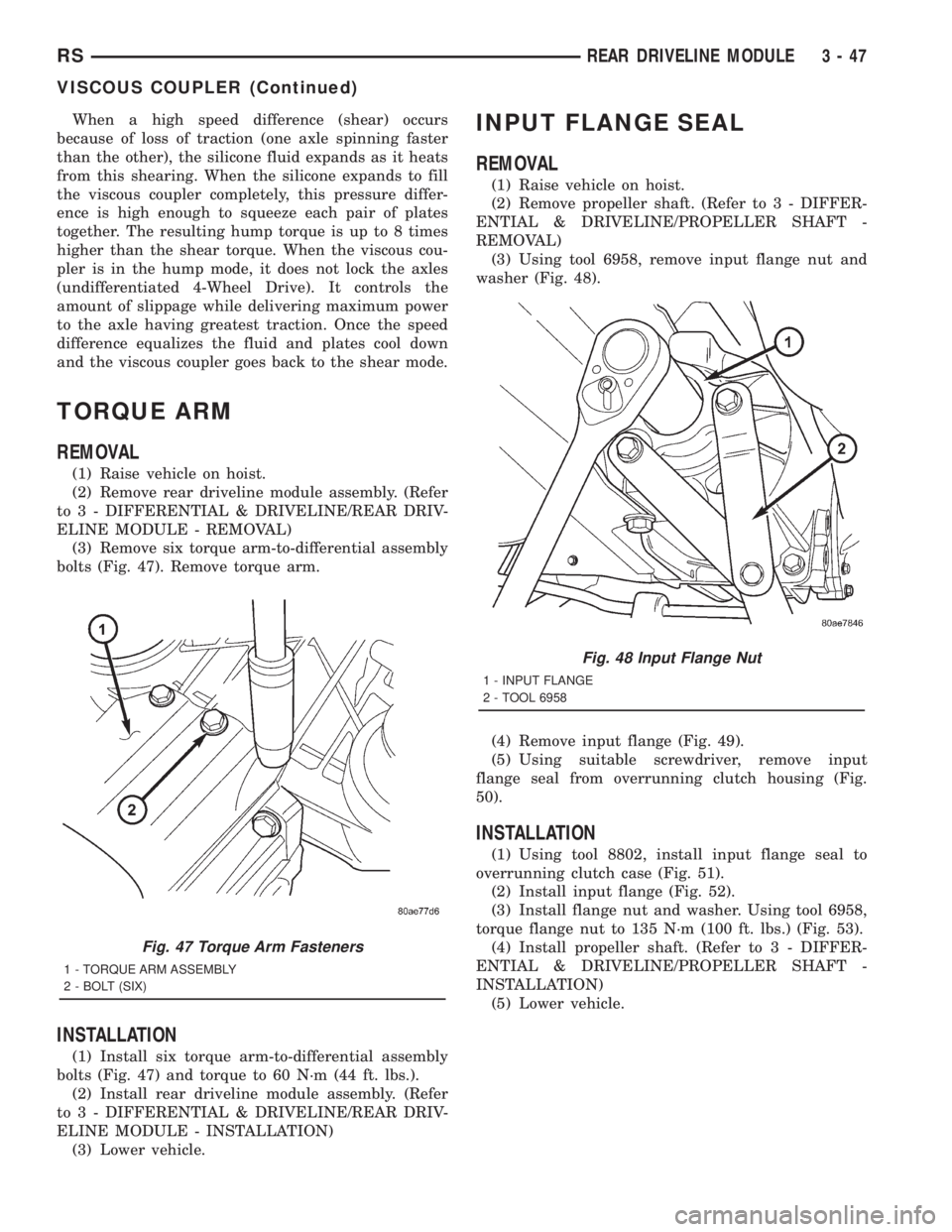
(3) Remove six torque arm-to-differential assembly
bolts (Fig. 47). Remove torque arm.
INSTALLATION
(1) Install six torque arm-to-differential assembly
bolts (Fig. 47) and torque to 60 N´m (44 ft. lbs.).
(2) Install rear driveline module assembly. (Refer
to 3 - DIFFERENTIAL & DRIVELINE/REAR DRIV-
ELINE MODULE - INSTALLATION)
(3) Lower vehicle.
INPUT FLANGE SEAL
REMOVAL
(1) Raise vehicle on hoist.
(2) Remove propeller shaft. (Refer to 3 - DIFFER-
ENTIAL & DRIVELINE/PROPELLER SHAFT -
REMOVAL)
(3) Using tool 6958, remove input flange nut and
washer (Fig. 48).
(4) Remove input flange (Fig. 49).
(5) Using suitable screwdriver, remove input
flange seal from overrunning clutch housing (Fig.
50).
INSTALLATION
(1) Using tool 8802, install input flange seal to
overrunning clutch case (Fig. 51).
(2) Install input flange (Fig. 52).
(3) Install flange nut and washer. Using tool 6958,
torque flange nut to 135 N´m (100 ft. lbs.) (Fig. 53).
(4) Install propeller shaft. (Refer to 3 - DIFFER-
ENTIAL & DRIVELINE/PROPELLER SHAFT -
INSTALLATION)
(5) Lower vehicle.
Fig. 47 Torque Arm Fasteners
1 - TORQUE ARM ASSEMBLY
2 - BOLT (SIX)
Fig. 48 Input Flange Nut
1 - INPUT FLANGE
2 - TOOL 6958
RSREAR DRIVELINE MODULE3-47
VISCOUS COUPLER (Continued)
Page 1626 of 4284
INSTALLATION
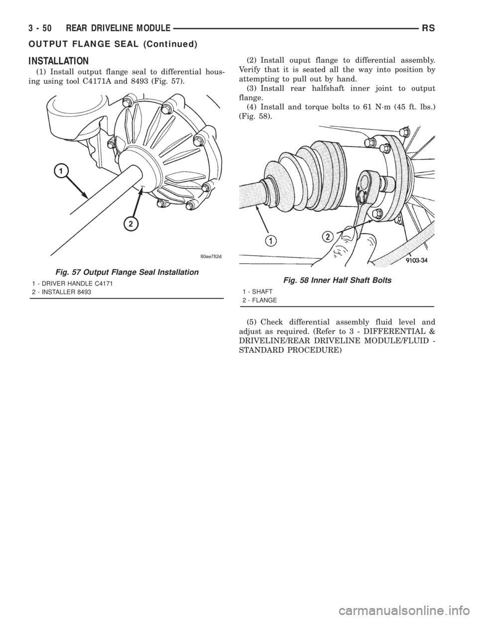
(1) Install output flange seal to differential hous-
ing using tool C4171A and 8493 (Fig. 57).(2) Install ouput flange to differential assembly.
Verify that it is seated all the way into position by
attempting to pull out by hand.
(3) Install rear halfshaft inner joint to output
flange.
(4) Install and torque bolts to 61 N´m (45 ft. lbs.)
(Fig. 58).
(5) Check differential assembly fluid level and
adjust as required. (Refer to 3 - DIFFERENTIAL &
DRIVELINE/REAR DRIVELINE MODULE/FLUID -
STANDARD PROCEDURE)
Fig. 57 Output Flange Seal Installation
1 - DRIVER HANDLE C4171
2 - INSTALLER 8493Fig. 58 Inner Half Shaft Bolts
1 - SHAFT
2 - FLANGE
3 - 50 REAR DRIVELINE MODULERS
OUTPUT FLANGE SEAL (Continued)
Page 1634 of 4284
(6) Check pedal travel. If pedal travel is excessive
or has not been improved, enough fluid has not
passed through the system to expel all the trapped
air. Be sure to monitor the fluid level in the pressure
bleeder, so it stays at a proper level so air will not
enter the brake system through the master cylinder.
(7) Perform a final adjustment of the rear brake
shoes (when applicable), then test drive vehicle to be
sure brakes are operating correctly and that pedal is
solid.
SPECIFICATIONS
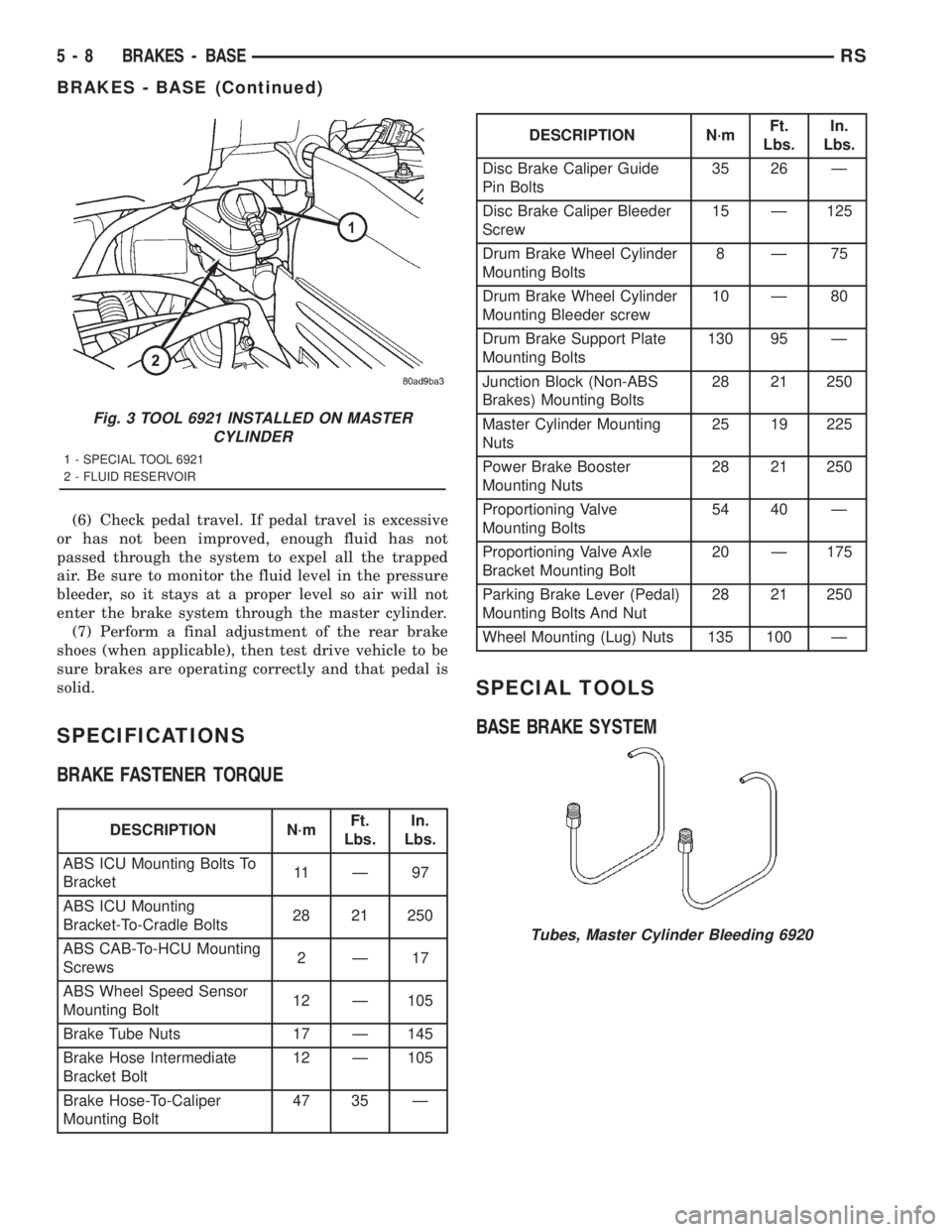
BRAKE FASTENER TORQUE
DESCRIPTION N´mFt.
Lbs.In.
Lbs.
ABS ICU Mounting Bolts To
Bracket11 Ð 9 7
ABS ICU Mounting
Bracket-To-Cradle Bolts28 21 250
ABS CAB-To-HCU Mounting
Screws2Ð17
ABS Wheel Speed Sensor
Mounting Bolt12 Ð 105
Brake Tube Nuts 17 Ð 145
Brake Hose Intermediate
Bracket Bolt12 Ð 105
Brake Hose-To-Caliper
Mounting Bolt47 35 Ð
DESCRIPTION N´mFt.
Lbs.In.
Lbs.
Disc Brake Caliper Guide
Pin Bolts35 26 Ð
Disc Brake Caliper Bleeder
Screw15 Ð 125
Drum Brake Wheel Cylinder
Mounting Bolts8Ð75
Drum Brake Wheel Cylinder
Mounting Bleeder screw10 Ð 80
Drum Brake Support Plate
Mounting Bolts130 95 Ð
Junction Block (Non-ABS
Brakes) Mounting Bolts28 21 250
Master Cylinder Mounting
Nuts25 19 225
Power Brake Booster
Mounting Nuts28 21 250
Proportioning Valve
Mounting Bolts54 40 Ð
Proportioning Valve Axle
Bracket Mounting Bolt20 Ð 175
Parking Brake Lever (Pedal)
Mounting Bolts And Nut28 21 250
Wheel Mounting (Lug) Nuts 135 100 Ð
SPECIAL TOOLS
BASE BRAKE SYSTEM
Fig. 3 TOOL 6921 INSTALLED ON MASTER
CYLINDER
1 - SPECIAL TOOL 6921
2 - FLUID RESERVOIR
Tubes, Master Cylinder Bleeding 6920
5 - 8 BRAKES - BASERS
BRAKES - BASE (Continued)
Page 1641 of 4284
shoes on the opposite side of the vehicle as well as
the shoes failing inspection.
If the brake shoe assemblies do not require
replacement, be sure to reinstall the brake shoes in
the original position they were remove from.
INSTALLATION - FRONT DISC BRAKE SHOES
(DISC/DISC BRAKES)
(1) Begin on one side of the vehicle or the other.
(2) Completely retract the caliper piston back into
its bore in the brake caliper (This is required for cal-
iper installation on the brake rotor with new brake
shoes installed).
(3) If applied, remove the protective paper from
the noise suppression gasket on the rear of both the
inner and outer brake shoe assemblies.
(4) Install the new inboard brake shoe into the cal-
iper piston by firmly pressing its retaining clip into
the piston bore. Be sure the inboard brake shoe is
positioned squarely against the face of the caliper
piston.
(5) Lubricate both adapter abutments where the
shoes slide with a small amount of MopartMultipur-
pose Lubricant, or equivalent.
(6) Slide the new outboard brake shoe into the cal-
iper adapter up against the outside of the brake
rotor.
CAUTION: Use care when installing the caliper
assembly onto the steering knuckle, so the caliper
guide pin bushings do not get damaged by the
steering knuckle bosses.
(7) Carefully position the brake caliper over the
brake rotor and adapter.
(8) Install the caliper guide pin bolts and tighten
to a torque of 35 N´m (26 ft. lbs.).Extreme caution
should be taken not to cross thread the caliper
guide pin bolts.
(9) Install the anti-rattle clip on the outboard side
of the caliper. Start the clip into the holes on the cal-
iper, then stretch the clip legs past the abutments on
the caliper adapter.
(10) Install the wheel and tire assembly. Tighten
the wheel mounting nuts in proper sequence until all
nuts are torqued to half specification, then repeat the
tightening sequence to the full specified torque of 135
N´m (100 ft. lbs.).
(11) Repeat the above procedure on other side of
the vehicle.
(12) Lower vehicle.
(13) Pump the brake pedal several times. This will
set the shoes to the brake rotor.
(14) Check and adjust brake fluid level as neces-
sary.(15) Road test the vehicle and make several stops
to wear off any foreign material on the brakes and to
seat the brake shoes.
INSTALLATION - FRONT DISC BRAKE SHOES
(DISC/DRUM BRAKES)
NOTE: Perform steps Step 1 through Step 5on each
side of the vehicle.
(1) Place the brake shoes in the adapter anti-rattle
clips.
(2) Completely retract the caliper piston back into
the bore of the caliper.
CAUTION: Use care when installing the caliper onto
the disc brake adapter to avoid damaging the boots
on the caliper guide pins.
(3) Install the disc brake caliper over the brake
shoes on the brake caliper adapter.
(4) Align the caliper guide pin bolt holes with the
guide pins. Install the caliper guide pin bolts and
tighten them to a torque of 35 N´m (26 ft. lbs.) (Fig.
14).
(5) Install the tire and wheel assembly. Tighten
the wheel mounting nuts to a torque of 135 N´m (100
ft. lbs.).
(6) Lower the vehicle.
(7) Pump the brake pedal several times. This will
set the shoes to the brake rotor.
(8) Check and adjust the brake fluid level as nec-
essary.
(9) Road test the vehicle and make several stops to
wear off any foreign material on the brakes and to
seat the brake shoes.
BRAKE PADS/SHOES - REAR
DISC
REMOVAL - REAR DISC BRAKE SHOES
(1) Raise vehicle on jackstands or centered on a
hoist. (Refer to LUBRICATION & MAINTENANCE/
HOISTING - STANDARD PROCEDURE).
(2) Remove rear wheel and tire assemblies from
vehicle.
(3) Remove the caliper to adapter guide pin bolts
(Fig. 15).
(4) Remove rear caliper from adapter using the fol-
lowing procedure. First rotate rear of caliper up from
the adapter. Then pull the front of the caliper and
the outboard brake shoe anti-rattle clip out from
under the front abutment on the adapter (Fig. 16).
RSBRAKES - BASE5-15
BRAKE PADS/SHOES - FRONT (Continued)
Page 1643 of 4284
CLEANING - DISC BRAKE SHOES
WARNING: DUST AND DIRT ACCUMULATING ON
BRAKE PARTS DURING NORMAL USE MAY CON-
TAIN ASBESTOS FIBERS FROM PRODUCTION OR
AFTERMARKET BRAKE LININGS. BREATHING
EXCESSIVE CONCENTRATIONS OF ASBESTOS
FIBERS CAN CAUSE SERIOUS BODILY HARM.
EXERCISE CARE WHEN SERVICING BRAKE
PARTS. DO NOT SAND OR GRIND BRAKE LINING
UNLESS EQUIPMENT USED IS DESIGNED TO CON-
TAIN THE DUST RESIDUE. DO NOT CLEAN BRAKE
PARTS WITH COMPRESSED AIR OR BY DRY
BRUSHING. CLEANING SHOULD BE DONE BY
DAMPENING THE BRAKE COMPONENTS WITH A
FINE MIST OF WATER, THEN WIPING THE BRAKE
COMPONENTS CLEAN WITH A DAMPENED CLOTH.
DISPOSE OF CLOTH AND ALL RESIDUE CONTAIN-
ING ASBESTOS FIBERS IN AN IMPERMEABLE
CONTAINER WITH THE APPROPRIATE LABEL. FOL-
LOW PRACTICES PRESCRIBED BY THE OCCUPA-
TIONAL SAFETY AND HEALTH ADMINISTRATION
(OSHA) AND THE ENVIRONMENTAL PROTECTION
AGENCY (EPA) FOR THE HANDLING, PROCESSING,
AND DISPOSING OF DUST OR DEBRIS THAT MAY
CONTAIN ASBESTOS FIBERS.
INSPECTION - DISC BRAKE SHOES
Visually inspect brake shoes (pads) for uneven lin-
ing wear. Also inspect for excessive lining deteriora-
tion. Check the clearance between the tips of the
wear indicators on the shoes (if equipped) and the
brake rotors.
If a visual inspection does not adequately deter-
mine the condition of the lining, a physical check will
be necessary. To check the amount of lining wear,
remove the disc brake shoes from the calipers.
Measure each brake shoe. The combined brake
shoe and its lining material thickness should be mea-
sured at its thinnest point.
²For front disc brake shoes, when a set of brake
shoes are worn to a thickness of approximately 7.95
mm (5/16 inch), they should be replaced.
²For rear disc brake shoes, when a set of brake
shoes are worn to a thickness of approximately 7.0
mm (9/32 inch), they should be replaced.
Replacebothdisc brake shoes (inboard and out-
board) on each caliper. It is necessary to replace the
shoes on the opposite side of the vehicle as well as
the shoes failing inspection.
If the brake shoe assemblies do not require
replacement, be sure to reinstall the brake shoes in
the original position they were remove from.
INSTALLATION - REAR DISC BRAKE SHOES
(1) Completely retract caliper piston back into pis-
ton bore of caliper assembly.
(2) Lubricate both adapter abutments where the
shoes contact with a liberal amount of MopartMul-
tipurpose Lubricant, or equivalent.
(3) If removed, install the brake rotor on the hub,
making sure it is squarely seated on the face of the
hub.
(4) Install the inboard brake shoe into the caliper
piston by firmly pressing it into the piston bore using
your thumbs. Be sure inboard brake shoe is posi-
tioned squarely against the face of the caliper piston.
(5) Install the outboard brake shoe on the disc
brake caliper. Be sure the outboard shoe is positioned
squarely against the outboard fingers of the caliper.
CAUTION: Use care when installing the caliper
assembly onto the adapter, so the caliper guide pin
bushings do not get damaged by the mounting
bosses.
(6) Carefully lower caliper and brake shoes over
rotor and onto adapter, reversing the removal proce-
dure (Fig. 16).
CAUTION: When installing the caliper guide pin
bolts extreme caution should be taken not to
crossthread the guide pin bolts.
(7) Install the caliper guide pin bolts. Tighten the
guide pin bolts to a torque of 35 N´m (26 ft. lbs.).
(8) Install the wheel and tire assembly. Tighten
the wheel mounting nuts in proper sequence until all
nuts are torqued to half specification. Then repeat
the tightening sequence to the full specified torque of
135 N´m (100 ft. lbs.).
(9) Remove jackstands or lower hoist.
CAUTION: Before moving vehicle, pump the brake
pedal several times to insure the vehicle has a firm
brake pedal to adequately stop the vehicle.
(10) Pump brake pedal several times to set brake
shoes to rotors.
(11) Check fluid level in reservoir.
(12) Road test the vehicle and make several stops
to wear off any foreign material on the brakes and to
seat the brake shoe linings.
RSBRAKES - BASE5-17
BRAKE PADS/SHOES - REAR DISC (Continued)
Page 1647 of 4284
(4) Insert Tool C-3784 into brake adjusting hole
and engage notches of brake adjusting screw star
wheel. Release brake by prying down with adjusting
tool.
(5) Remove the rear brake drum from the rear hub
and bearing assembly.
(6) Inspect brake lining for wear, shoe alignment,
and or contamination from grease or brake fluid.
INSTALLATION - REAR DRUM BRAKE SHOES
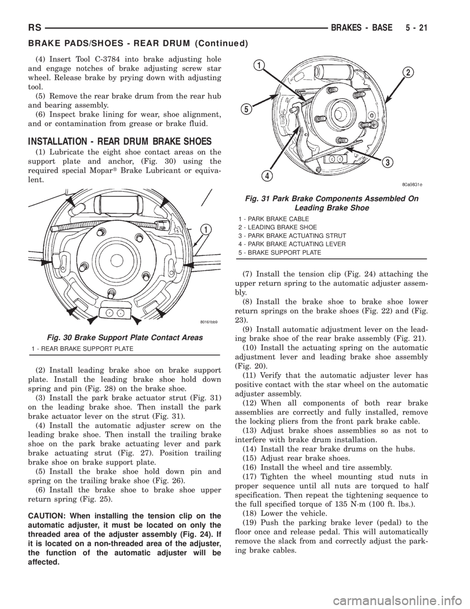
(1) Lubricate the eight shoe contact areas on the
support plate and anchor, (Fig. 30) using the
required special MopartBrake Lubricant or equiva-
lent.
(2) Install leading brake shoe on brake support
plate. Install the leading brake shoe hold down
spring and pin (Fig. 28) on the brake shoe.
(3) Install the park brake actuator strut (Fig. 31)
on the leading brake shoe. Then install the park
brake actuator lever on the strut (Fig. 31).
(4) Install the automatic adjuster screw on the
leading brake shoe. Then install the trailing brake
shoe on the park brake actuating lever and park
brake actuating strut (Fig. 27). Position trailing
brake shoe on brake support plate.
(5) Install the brake shoe hold down pin and
spring on the trailing brake shoe (Fig. 26).
(6) Install the brake shoe to brake shoe upper
return spring (Fig. 25).
CAUTION: When installing the tension clip on the
automatic adjuster, it must be located on only the
threaded area of the adjuster assembly (Fig. 24). If
it is located on a non-threaded area of the adjuster,
the function of the automatic adjuster will be
affected.(7) Install the tension clip (Fig. 24) attaching the
upper return spring to the automatic adjuster assem-
bly.
(8) Install the brake shoe to brake shoe lower
return springs on the brake shoes (Fig. 22) and (Fig.
23).
(9) Install automatic adjustment lever on the lead-
ing brake shoe of the rear brake assembly (Fig. 21).
(10) Install the actuating spring on the automatic
adjustment lever and leading brake shoe assembly
(Fig. 20).
(11) Verify that the automatic adjuster lever has
positive contact with the star wheel on the automatic
adjuster assembly.
(12) When all components of both rear brake
assemblies are correctly and fully installed, remove
the locking pliers from the front park brake cable.
(13) Adjust brake shoes assemblies so as not to
interfere with brake drum installation.
(14) Install the rear brake drums on the hubs.
(15) Adjust rear brake shoes.
(16) Install the wheel and tire assembly.
(17) Tighten the wheel mounting stud nuts in
proper sequence until all nuts are torqued to half
specification. Then repeat the tightening sequence to
the full specified torque of 135 N´m (100 ft. lbs.).
(18) Lower the vehicle.
(19) Push the parking brake lever (pedal) to the
floor once and release pedal. This will automatically
remove the slack from and correctly adjust the park-
ing brake cables.
Fig. 30 Brake Support Plate Contact Areas
1 - REAR BRAKE SUPPORT PLATE
Fig. 31 Park Brake Components Assembled On
Leading Brake Shoe
1 - PARK BRAKE CABLE
2 - LEADING BRAKE SHOE
3 - PARK BRAKE ACTUATING STRUT
4 - PARK BRAKE ACTUATING LEVER
5 - BRAKE SUPPORT PLATE
RSBRAKES - BASE5-21
BRAKE PADS/SHOES - REAR DRUM (Continued)
Page 1651 of 4284
(7) Reinstall the caliper on the vehicle and bleed
the brakes as necessary. Refer to Installation in this
section.
INSTALLATION - FRONT DISC BRAKE CALIPER
(DISC/DISC BRAKES)
CAUTION: TRW and Continental Teves brake cali-
pers are not interchangeable. Each caliper is specif-
ically designed for the unique brake system (TRW -
disc/drum brake combination and Continental Teves
- disc/disc brake combination). If calipers are inter-
changed, improper performance, noise and
increased stopping distance can occur.
(1) Completely retract the caliper piston back into
piston bore of the caliper. Use a C-clamp to retract
the piston if necessary. Place a wood block over the
piston before installing the C-clamp to avoid damag-
ing the piston.
CAUTION: Use care when installing the brake cali-
per assembly onto the steering knuckle, so that the
seals on the caliper guide pin bushings do not get
damaged by the steering knuckle bosses.
(2) Carefully position the brake caliper and shoes
over the brake rotor and adapter.
(3) Install the caliper guide pin bolts and tighten
to a torque of 35 N´m (26 ft. lbs.).Extreme caution
should be taken not to cross thread the caliper
guide pin bolts.
(4) Install the anti-rattle clip on the outboard side
of the caliper. Start the clip into the holes on the cal-
iper, then stretch the clip legs past the abutments on
the caliper adapter.
CAUTION: When connecting the brake hose to the
caliper, install new brake hose to caliper special
copper washers.
(5) Install the brake hose on the caliper. To do
this, first place one NEW special fitting washer on
each side of the hose fitting, then slide the banjo bolt
through the fitting. Next, thread the banjo bolt into
the threaded port on the rear of the brake caliper.
Tighten the banjo bolt to a torque of 47 N´m (35 ft.
lbs.).
(6) Install the wheel and tire assembly. Tighten
the wheel mounting stud nuts in proper sequence
until all nuts are torqued to half specification, then
repeat the tightening sequence to the full specified
torque of 135 N´m (100 ft. lbs.).
(7) Lower the vehicle.
(8) Remove the brake pedal depressor (holding)
tool.
(9) Bleed the hydraulic brake circuit to the brake
caliper. (Refer to 5 - BRAKES - STANDARD PROCE-
DURE)
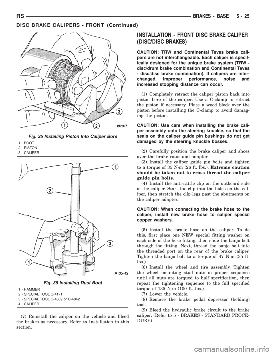
Fig. 35 Installing Piston Into Caliper Bore
1 - BOOT
2 - PISTON
3 - CALIPER
Fig. 36 Installing Dust Boot
1 - HAMMER
2 - SPECIAL TOOL C-4171
3 - SPECIAL TOOL C-4689 or C-4842
4 - CALIPER
RSBRAKES - BASE5-25
DISC BRAKE CALIPERS - FRONT (Continued)