2001 CHRYSLER VOYAGER ECO mode
[x] Cancel search: ECO modePage 2072 of 4284
OPERATION
Each Sentry Key has a unique transponder identi-
fication code permanently programmed into it by the
manufacturer. Likewise, the SKIM has a unique
9Secret Key9code programmed into it by the manu-
facturer as well. When a Sentry Key is programmed
into the memory of the SKIM, the SKIM stores the
transponder identification code from the Sentry Key,
and the Sentry Key learns the9Secret Key9code from
the SKIM. Once the Sentry Key learns the9Secret
Key9code of the SKIM, it is also permanently pro-
grammed into the transponder's memory. Therefore,
blank keys for the SKIS must be programmed by the
SKIM in addition to being cut to match the mechan-
ical coding of the ignition lock cylinder. Refer to Elec-
trical, Vehicle Theft Security, Transponder Key,
Standard Procedure - Transponder Programming.
The Sentry Key's transponder is within the range
of the SKIM's transceiver antenna ring when it is
inserted into the ignition lock cylinder. When the
ignition switch is turned to the ON position, the
SKIM communicates with the Sentry Key via a radio
frequency (RF) signal. The SKIM determines if a
valid key is present based on the information it
receives from the Sentry Key. If a valid key is
detected, that fact is communicated to the PCM via
the PCI bus and the vehicle is allowed to continue
running. If an invalid key is received by the PCM or
no status at all is communicated, the vehicle will
stall after two (2) seconds of running. The indicator
light will be flashing at this point. The Sentry Key's
transponder can not be repaired. If it is faulty or
damaged, it must be replaced.
Common communication problems:
²Two transponder keys too close together.
²Speed Pass too close to transponder key.
Solid indicator that there is a system failure.
²Loss of PCM communication.
²Failed antenna circuit.
STANDARD PROCEDURE - TRANSPONDER
PROGRAMMING
USING A DRB IIITSCAN TOOL
All Sentry Keys included with the vehicle are pre-
programmed to work with the Sentry Key Immobi-
lizer System (SKIS) when it is shipped from the
factory. The Sentry Key Immobilizer Module (SKIM)
can be programmed to recognize up to a total of eight
Sentry Keys. When programming a blank Sentry Key
transponder, the key must first be cut to match the
ignition lock cylinder of the vehicle for which it will
be used. The vehicle's four digit PIN code will be
required to complete this task since you will need it
to enter the Secured Access Mode in the SKIM. Thefollowing steps must be completed using a DRB IIIt
scan tool:
(1) Insert the blank key into the ignition and turn
it to the RUN position.
(2) Using a DRB IIItscan tool, select9Theft
Alarm,99SKIM,99Miscellaneous,9and then9Program
New Key.9
(3) Enter the four digit PIN code using the DRB
IIItscan tool. When programming is completed, the
SKIM will exit Secured Access Mode and the DRB
IIItscan tool will display the results of your attempt
to program the key. One of five distinct results may
be displayed. All five are listed below:
²(Programming Successful(is displayed if the
Sentry Key programming is successful.
²(Learned Key in Ignition(is displayed if the
key in the ignition has already been programmed
into that vehicle's SKIM.
²(Eight Keys Already Learned (At The Maxi-
mum) Programming Not Done(is displayed if
eight keys have already been programmed into the
SKIM. In this case, if a new key needs to be added
due to a lost or defective key, the9Erase All Keys9
command (which requires entering the Secured
Access Mode) has to be performed. Following the
9Erase All Keys9command, all keys that will be used
to operate the vehicleMUSTbe reprogrammed to
the SKIM.
²(Programming Not Attempted(is displayed
after an9Erase All Keys9function is executed.
²(Programming Key Failed(is displayed if fur-
ther diagnosis is required.
To learn additional keys, turn the ignition OFF,
remove the learned key, insert the next new blank
key, and repeat the steps from the beginning.
ªCUSTOMER LEARNº MODE
This feature is only available on domestic vehicles
or those which have a U.S. country code designator.
This procedure requires access to at least two valid
Sentry Keys. If two valid Sentry Keys are not avail-
able, Sentry Key programming will require the use of
a DRB IIItscan tool.
The steps required to program Sentry Keys with
two valid Sentry Keys follows:
(1) Obtain the blank Sentry Key(s) that need to be
programmed. Cut the keys to match the ignition lock
cylinder mechanical key codes.
(2) Insert one of the two valid Sentry Keys into the
ignition switch and turn the ignition switch to the
ON position.
(3) After the ignition switch has been in the ON
position for longer than three seconds, but no more
than fifteen seconds, cycle the ignition switch back to
8Q - 4 VEHICLE THEFT SECURITYRS
TRANSPONDER KEY (Continued)
Page 2073 of 4284
the OFF position. Replace the first valid Sentry Key
in the ignition lock cylinder with the second valid
Sentry Key and turn the ignition switch back to the
ON position. The second valid Sentry Key must be
inserted within 15 seconds of removing the first valid
Sentry key.
(4) About ten seconds after the completion of Step
3, the indicator light will start to flash and a single
audible chime tone will sound to indicate that the
system has entered the9Customer Learn9program-
ming mode.
(5) Within sixty seconds of entering the9Customer
Learn9programming mode, turn the ignition switch
to the OFF position, replace the valid Sentry Key
with a blank Sentry Key transponder, and turn the
ignition switch back to the ON position.
(6) About ten seconds after the completion of Step
5, a single audible chime tone will sound and the
indicator light will stop flashing and stay on solid for
three seconds and then turn off to indicate that the
blank Sentry Key has been successfully programmed.
The SKIS will immediately exit the9Customer
Learn9programming mode and the vehicle may be
started using the newly programmed Sentry Key.
These steps must be completed in their entirety for
each additional Sentry Key to be programmed. If any
of the above steps are not completed in the given
sequence, or within the allotted time, the SKIS will
exit the9Customer Learn9programming mode and
the programming will be unsuccessful. The SKIS will
also automatically exit the9Customer Learn9pro-
gramming mode if:
²It sees a non-blank Sentry Key when it should
see a blank.
²If it has already programmed eight (8) valid
Sentry Keys.
²If the ignition switch is turned to the OFF posi-
tion for more than about fifty (50) seconds.
NOTE: If you attempt to start the vehicle while in
ªCustomer Learnº mode (LED flashing), the vehicle
will behave as though an invalid key is being used
(i.e. the engine will stall after two (2) seconds of
running). No faults will be logged.
NOTE: Once a Sentry Key has been programmed to
a particular vehicle, it cannot be used on any other
vehicle.VTSS/SKIS INDICATOR LAMP
DESCRIPTION
The Sentry Key Immobilizer System (SKIS) uses
an indicator light to convey information on the status
of the system to the customer. This light is shared
with the Vehicle Theft Security System (VTSS). The
light is located in the Message Center. The indicator
light is controlled by the Body Control Module (BCM)
based upon messages it receives from the Sentry Key
Immobilizer Module (SKIM) on the PCI bus.
OPERATION
The BCM performs a four second bulb check,
regardless of SKIM messages. After the bulb check,
the lamp is controlled according to SKIM messages.
Then, the SKIM sends messages to the BCM to oper-
ate the light based upon the results of the SKIS self
tests. The light may be actuated in two possible
ways, flashing or on solid. If the light comes on and
stays on solid after a power-up test, this indicates
that the SKIM has detected a system malfunction. If
the SKIM detects an invalid key when the ignition
switch is moved to the ON position, it sends a mes-
sage on the PCI bus to the BCM, to flash the light.
The SKIM can also send a message to flash the light
and generate a single audible chime at the same
time. These two events occurring simultaneously
indicate that the SKIS has been placed into the9Cus-
tomer Learn9mode. Refer to Electrical, Vehicle Theft
Security, Transponder Key, Standard Procedure -
Transponder Programming for more information on
the9Customer Learn9mode. If the light comes on
and stays on after the power-up test, diagnosis of the
SKIS should be performed using a DRB IIItscan tool
and the appropriate Body Diagnostic Procedures
manual. The light is not a serviceable component.
RSVEHICLE THEFT SECURITY8Q-5
TRANSPONDER KEY (Continued)
Page 2075 of 4284
WIPERS/WASHERS
TABLE OF CONTENTS
page page
WIPERS/WASHERS
DESCRIPTION............................1
OPERATION.............................1
DIAGNOSIS AND TESTING..................2
FRONT WIPER SYSTEM..................2
REAR WIPER SYSTEM...................2
FRONT WIPER/WASHER SWITCH...........2
FAILED PARK SWITCH...................2
FRONT WIPER ARMS
REMOVAL...............................4
INSTALLATION............................4
ADJUSTMENTS...........................4
FRONT WIPER MOTOR
REMOVAL...............................5
INSTALLATION............................5
FRONT WIPER UNIT
REMOVAL...............................5
INSTALLATION............................6
REAR WIPER ARM
REMOVAL...............................6
INSTALLATION............................7
REAR WIPER MOTOR
REMOVAL...............................7INSTALLATION............................7
REAR WIPER/WASHER SWITCH
DESCRIPTION............................7
OPERATION.............................7
WASHER HOSES
REMOVAL...............................7
INSTALLATION............................8
WASHER RESERVOIR
REMOVAL...............................8
INSTALLATION............................8
WIPER BLADES
REMOVAL...............................9
CLEANING...............................9
INSTALLATION............................9
WIPER BLADE ELEMENTS
REMOVAL...............................9
INSTALLATION...........................10
WIPER LINKAGE
REMOVAL..............................10
INSTALLATION...........................10
WIPERS/WASHERS
DESCRIPTION
FRONT WIPER/WASHER SYSTEM
The windshield wipers can be operated with the
windshield wiper switch when the ignition switch is
in the RUN or ACCESSORY positions. The wind-
shield wiper system is protected by a 30 amp fuse (9)
located in the Power Distribution Center (PDC) part
of the Integrated Power Module (IPM) in the engine
compartment. The wiper/washer switch is integral to
the multi-function switch. It is a resistive MUX
switch that sends inputs to the BCM to operate the
wiper/washer system.
REAR WIPER/WASHER SYSTEM
The rear windshield wiper and washers can be
operated when the ignition switch is in the RUN or
ACCESSORY positions.
OPERATION
FRONT WIPER/WASHER SYSTEM
The windshield washer circuit is protected by a 9
amp PTC located in the Junction Block. The wiper
motor has permanent magnetic fields. The speeds are
determined by current flow to the appropriate set of
brushes inside the motor. The current flow is con-
trolled by the multi-function switch stalk mounted
wiper switch, high speed/low speed relays located in
the Power Distribution Center (PDC) part of the
Integrated Power Module (IPM) in the engine com-
partment. The speed sensitive intermittent wiper is
controlled by the Body Control Module (BCM). The
intermittent mode, with the vehicle traveling greater
than 10.4 mph, has a range of 0.5 to 18 seconds.
With the vehicle traveling less than 10.4 mph, and
the time delay is not adjusted, time delay doubles to
a range of 1 to 36 seconds. The wiper arms will park
at the base of the windshield just above the cowl
cover after the wiper switch is turned OFF.
RSWIPERS/WASHERS8R-1
Page 2076 of 4284
The windshield wiper motor and linkage is located
in an integral wiper unit at the rear of the engine
compartment. The wiper unit must be removed to
gain access to the wiper motor.
REAR WIPER/WASHER SYSTEM
When continuous rear wiper operation is required,
the Body Control Module (BCM) will provide ignition
ON voltage to the rear wiper motor. When the wiper
switch is turned OFF, the BCM provides circuit
ground to operate the motor until the wipe cycle is
complete and the wiper arm returns to the base of
the rear window.
When intermittent rear wiper mode is selected, the
wiper motor will cycle every 7 seconds. The intermit-
tent delay time is also adjusted based upon vehicle
speed. With the vehicle traveling greater at 50 mph,
the cycle changes to every 5 seconds. DIAGNOSIS
AND TESTING
DIAGNOSIS AND TESTING - FRONT WIPER
SYSTEM
The windshield wiper system operates in several
modes:
²Low and high speed normal wipe
²Speed sensitive intermittent wipe
²Wipe after wash
²Pulse wipe
²Park (switch OFF)
The windshield wiper circuits are continuously
monitored and controlled by the Body Control Mod-
ule (BCM). If a problem occurs in the electronic com-
ponents, wiring, switch (except integral motor park
switch) and wiper motor a Diagnostic Trouble Code
(DTC) will be stored in the BCM memory. DTC's can
be retrieved using a DRB IIItscan tool. Refer to the
proper Body Diagnostic Procedures manual for DTC
descriptions and retrieval information.
The windshield wiper park switch and circuit is
monitored by the BCM. The park switch and circuit
can be tested using the Wiper System Diagnosis
table.
DIAGNOSIS AND TESTING - REAR WIPER
SYSTEM
The rear window wiper system operates in several
modes:
²Continuous wipe
²Intermittent wipe
²Wash
²Wipe after wash
The windshield wiper circuits are continuously
monitored and controlled by the Body Control Mod-
ule (BCM). If a problem occurs in the electronic com-
ponents, wiring, switch (except integral motor parkswitch) and wiper motor a Diagnostic Trouble Code
(DTC) will be stored in the BCM memory. The
DTC(s) can be retrieved using a DRB IIItscan tool.
DIAGNOSIS AND TESTING - FRONT
WIPER/WASHER SWITCH
To test the front wiper/washer portion of the multi-
function switch:
(1) Remove the multi-function switch (Refer to 8 -
ELECTRICAL/LAMPS/LIGHTING - EXTERIOR/
MULTI-FUNCTION SWITCH - REMOVAL).
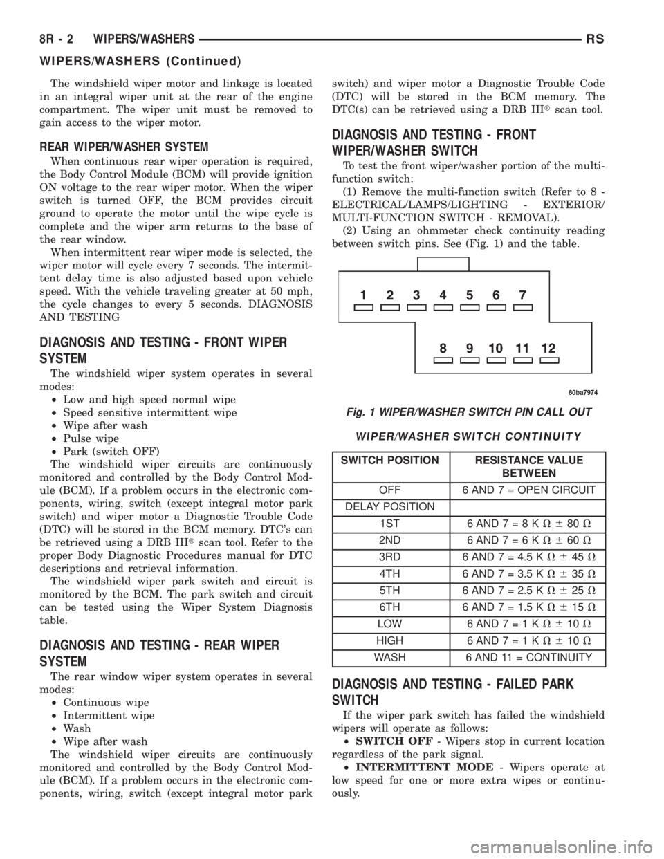
(2) Using an ohmmeter check continuity reading
between switch pins. See (Fig. 1) and the table.
WIPER/WASHER SWITCH CONTINUITY
SWITCH POSITION RESISTANCE VALUE
BETWEEN
OFF 6 AND 7 = OPEN CIRCUIT
DELAY POSITION
1ST 6AND7=8KV680V
2ND 6AND7=6KV660V
3RD 6 AND 7 = 4.5 KV645V
4TH 6 AND 7 = 3.5 KV635V
5TH 6 AND 7 = 2.5 KV625V
6TH 6 AND 7 = 1.5 KV615V
LOW 6AND7=1KV610V
HIGH 6 AND7=1KV610V
WASH 6 AND 11 = CONTINUITY
DIAGNOSIS AND TESTING - FAILED PARK
SWITCH
If the wiper park switch has failed the windshield
wipers will operate as follows:
²SWITCH OFF- Wipers stop in current location
regardless of the park signal.
²INTERMITTENT MODE- Wipers operate at
low speed for one or more extra wipes or continu-
ously.
Fig. 1 WIPER/WASHER SWITCH PIN CALL OUT
8R - 2 WIPERS/WASHERSRS
WIPERS/WASHERS (Continued)
Page 2850 of 4284
CATALYTIC CONVERTER
DESCRIPTION
The toe board three-way catalytic converter is con-
nected to the exhaust manifold by the use of flex
joint and a gasket. The outlet connects to the muffler
inlet pipe and is secured with a band type clamp
(Fig. 1).
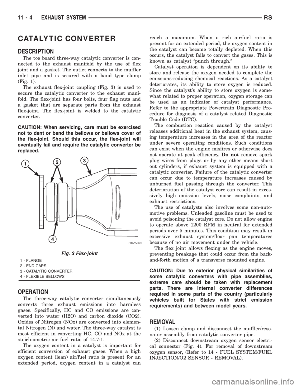
The exhaust flex-joint coupling (Fig. 3) is used to
secure the catalytic converter to the exhaust mani-
fold. The flex-joint has four bolts, four flag nuts and
a gasket that are separate parts from the exhaust
flex-joint. The flex-joint is welded to the catalytic
converter.
CAUTION: When servicing, care must be exercised
not to dent or bend the bellows or bellows cover of
the flex-joint. Should this occur, the flex-joint will
eventually fail and require the catalytic converter be
replaced.
OPERATION
The three-way catalytic converter simultaneously
converts three exhaust emissions into harmless
gases. Specifically, HC and CO emissions are con-
verted into water (H2O) and carbon dioxide (CO2).
Oxides of Nitrogen (NOx) are converted into elemen-
tal Nitrogen (N) and water. The three-way catalyst is
most efficient in converting HC, CO and NOx at the
stoichiometric air fuel ratio of 14.7:1.
The oxygen content in a catalyst is important for
efficient conversion of exhaust gases. When a high
oxygen content (lean) air/fuel ratio is present for an
extended period, oxygen content in a catalyst canreach a maximum. When a rich air/fuel ratio is
present for an extended period, the oxygen content in
the catalyst can become totally depleted. When this
occurs, the catalyst fails to convert the gases. This is
known as catalyst9punch through.9
Catalyst operation is dependent on its ability to
store and release the oxygen needed to complete the
emissions-reducing chemical reactions. As a catalyst
deteriorates, its ability to store oxygen is reduced.
Since the catalyst's ability to store oxygen is some-
what related to proper operation, oxygen storage can
be used as an indicator of catalyst performance.
Refer to the appropriate Powertrain Diagnostic Pro-
cedure for diagnosis of a catalyst related Diagnostic
Trouble Code (DTC).
The combustion reaction caused by the catalyst
releases additional heat in the exhaust system, caus-
ing temperature increases in the area of the reactor
under severe operating conditions. Such conditions
can exist when the engine misfires or otherwise does
not operate at peak efficiency.Do notremove spark
plug wires from plugs or by any other means short
out cylinders, if exhaust system is equipped with a
catalytic converter. Failure of the catalytic converter
can occur due to temperature increases caused by
unburned fuel passing through the converter. This
deterioration of the catalyst core can result in exces-
sively high emission levels, noise complaints, and
exhaust restrictions.
The use of catalysts also involves some non-auto-
motive problems. Unleaded gasoline must be used to
avoid poisoning the catalyst core. Do not allow engine
to operate above 1200 RPM in neutral for extended
periods over 5 minutes. This condition may result in
excessive exhaust system/floor pan temperatures
because of no air movement under the vehicle.
The flex joint allows flexing as the engine moves,
preventing breakage that could occur from the back-
and-forth motion of a transverse mounted engine.
CAUTION: Due to exterior physical similarities of
some catalytic converters with pipe assemblies,
extreme care should be taken with replacement
parts. There are internal converter differences
required in some parts of the country (particularly
vehicles built for States with strict emission
requirements) and between model years.
REMOVAL
(1) Loosen clamp and disconnect the muffler/reso-
nator assembly from catalytic converter pipe.
(2) Disconnect downstream oxygen sensor electri-
cal connector (Fig. 4). For removal of downstream
oxygen sensor, (Refer to 14 - FUEL SYSTEM/FUEL
INJECTION/O2 SENSOR - REMOVAL).
Fig. 3 Flex-joint
1 - FLANGE
2 - END CAPS
3 - CATALYTIC CONVERTER
4 - FLEXIBLE BELLOWS
11 - 4 EXHAUST SYSTEMRS
Page 2882 of 4284
(3) Put the tip of each injector into their ports.
Push the assembly into place until the injectors are
seated in the ports.
(4) Install the fuel rail mounting bolts. Tighten
bolts to 22 N´m (200 in. lbs.) torque.
(5) Remove covering on lower intake manifold and
clean surface.
(6) Install the Upper Intake Manifold, refer to
Engine/Manifolds/Upper Intake for more information.
(7) Install fuel hose quick connector fitting to chas-
sis tubes.Refer to Fuel Hoses, Clamps and
Quick Connect Fittings in this Section.Push the
fitting onto the chassis tube until it clicks into place.
Pull on the fitting to ensure complete insertion.
(8) Connect negative cable to battery.
(9) Use the DRBIIItscan tool to pressurize the
fuel system. Check for leaks.
FUEL TANK
DESCRIPTION
The fuel tank is constructed of a plastic material.
Its main functions are for fuel storage and for place-
ment of the fuel pump module. The tank is made
from High density Polyethylene (HDPE) material.If
equipped with ORVR (Onboard Refueling Vapor
Recovery) it has been added to the fuel tank to con-
trol refueling vapor emissions.
OPERATION
All models pass a full 360 degree rollover test
without fuel leakage. To accomplish this, fuel and
vapor flow controls are required for all fuel tank con-
nections.
All models are equipped with either one or two
rollover valves mounted into the top of the fuel tank
(or pump module).
An evaporation control system is connected to the
rollover valve(s)/control valves(Refer to 25 - EMIS-
SIONS CONTROL/EVAPORATIVE EMISSIONS/
ORVR - OPERATION) to reduce emissions of fuel
vapors into the atmosphere. When fuel evaporates
from the fuel tank, vapors pass through vent hoses or
tubes to a charcoal canister where they are tempo-
rarily held. When the engine is running, the vapors
are drawn into the intake manifold. In addition, fuel
vapors produced during vehicle refueling are allowed
to pass through the vent hoses/tubes to the charcoal
canister(s) for temporary storage (prior to being
drawn into the intake manifold). All models areequipped with a self-diagnosing system using a Leak
Detection Pump (LDP). Refer to the Emission Control
System for additional information.
INLET CHECK VALVE
All vehicles have an inlet check valve on the inside
of the fuel tank at the filler inlet
The valve prevents fuel from splashing back on
customer during vehicle refueling. The valve is a
non-serviceable item.
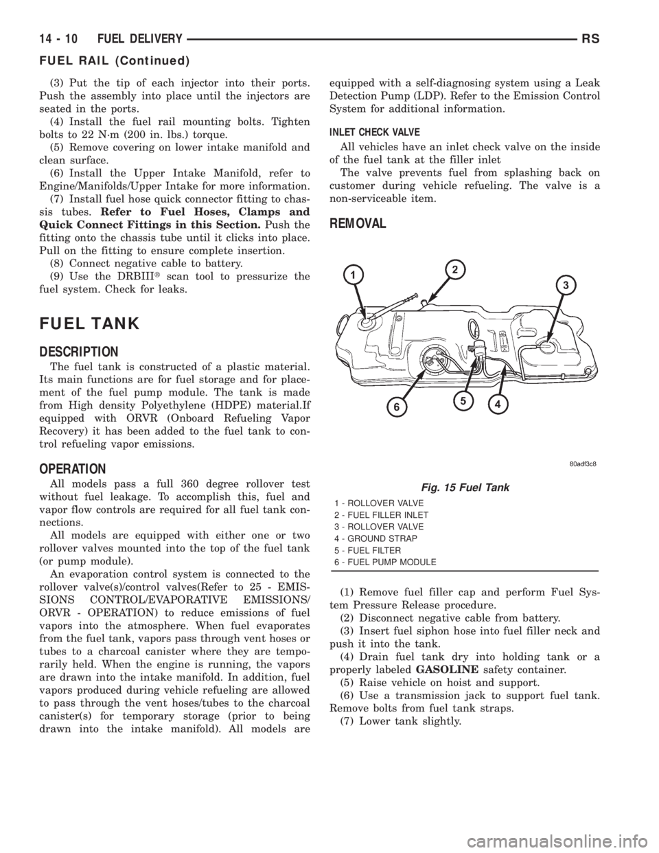
REMOVAL
(1) Remove fuel filler cap and perform Fuel Sys-
tem Pressure Release procedure.
(2) Disconnect negative cable from battery.
(3) Insert fuel siphon hose into fuel filler neck and
push it into the tank.
(4) Drain fuel tank dry into holding tank or a
properly labeledGASOLINEsafety container.
(5) Raise vehicle on hoist and support.
(6) Use a transmission jack to support fuel tank.
Remove bolts from fuel tank straps.
(7) Lower tank slightly.
Fig. 15 Fuel Tank
1 - ROLLOVER VALVE
2 - FUEL FILLER INLET
3 - ROLLOVER VALVE
4 - GROUND STRAP
5 - FUEL FILTER
6 - FUEL PUMP MODULE
14 - 10 FUEL DELIVERYRS
FUEL RAIL (Continued)
Page 2889 of 4284
the PCM must calculate a different injector pulse
width and ignition timing for idle than it does for
Wide Open Throttle (WOT). There are several differ-
ent modes of operation that determine how the PCM
responds to the various input signals.
There are two different areas of operation, OPEN
LOOP and CLOSED LOOP.
During OPEN LOOP modes the PCM receives
input signals and responds according to preset PCM
programming. Inputs from the upstream and down-
stream heated oxygen sensors are not monitored dur-
ing OPEN LOOP modes, except for heated oxygen
sensor diagnostics (they are checked for shorted con-
ditions at all times).
During CLOSED LOOP modes the PCM monitors
the inputs from the upstream and downstream
heated oxygen sensors. The upstream heated oxygen
sensor input tells the PCM if the calculated injector
pulse width resulted in the ideal air-fuel ratio of 14.7
to one. By monitoring the exhaust oxygen content
through the upstream heated oxygen sensor, the
PCM can fine tune injector pulse width. Fine tuning
injector pulse width allows the PCM to achieve opti-
mum fuel economy combined with low emissions.
For the PCM to enter CLOSED LOOP operation,
the following must occur:
(1) Engine coolant temperature must be over 35ÉF.
²If the coolant is over 35É the PCM will wait 44
seconds.
²If the coolant is over 50ÉF the PCM will wait 38
seconds.
²If the coolant is over 167ÉF the PCM will wait
11 seconds.
(2) For other temperatures the PCM will interpo-
late the correct waiting time.
(3) O2 sensor must read either greater than 0.745
volts or less than 0.1 volt.
(4) The multi-port fuel injection systems has the
following modes of operation:
²Ignition switch ON (Zero RPM)
²Engine start-up
²Engine warm-up
²Cruise
²Idle
²Acceleration
²Deceleration
²Wide Open Throttle
²Ignition switch OFF
(5) The engine start-up (crank), engine warm-up,
deceleration with fuel shutoff and wide open throttle
modes are OPEN LOOP modes. Under most operat-
ing conditions, the acceleration, deceleration (with
A/C on), idle and cruise modes,with the engine at
operating temperatureare CLOSED LOOP modes.IGNITION SWITCH ON (ZERO RPM) MODE
When the ignition switch activates the fuel injec-
tion system, the following actions occur:
²The PCM monitors the engine coolant tempera-
ture sensor and throttle position sensor input. The
PCM determines basic fuel injector pulse width from
this input.
²The PCM determines atmospheric air pressure
from the MAP sensor input to modify injector pulse
width.
When the key is in the ON position and the engine
is not running (zero rpm), the Auto Shutdown (ASD)
and fuel pump relays de-energize after approximately
1 second. Therefore, battery voltage is not supplied to
the fuel pump, ignition coil, fuel injectors and heated
oxygen sensors.
ENGINE START-UP MODE
This is an OPEN LOOP mode. If the vehicle is in
park or neutral (automatic transaxles) or the clutch
pedal is depressed (manual transaxles) the ignition
switch energizes the starter relay. The following
actions occur when the starter motor is engaged.
²If the PCM receives the camshaft position sensor
and crankshaft position sensor signals, it energizes
the Auto Shutdown (ASD) relay and fuel pump relay.
If the PCM does not receive both signals within
approximately one second, it will not energize the
ASD relay and fuel pump relay. The ASD and fuel
pump relays supply battery voltage to the fuel pump,
fuel injectors, ignition coil and heated oxygen sen-
sors.
²The PCM energizes the injectors (on the 69É
degree falling edge) for a calculated pulse width until
it determines crankshaft position from the camshaft
position sensor and crankshaft position sensor sig-
nals. The PCM determines crankshaft position within
1 engine revolution.
²After determining crankshaft position, the PCM
begins energizing the injectors in sequence. It adjusts
injector pulse width and controls injector synchroni-
zation by turning the individual ground paths to the
injectors On and Off.
²When the engine idles within664 RPM of its
target RPM, the PCM compares current MAP sensor
value with the atmospheric pressure value received
during the Ignition Switch On (zero RPM) mode.
Once the ASD and fuel pump relays have been
energized, the PCM determines injector pulse width
based on the following:
²Battery voltage
²Engine coolant temperature
²Engine RPM
²Inlet/Intake air temperature (IAT)
²MAP
²Throttle position
RSFUEL INJECTION14-17
FUEL INJECTION (Continued)
Page 2890 of 4284
²The number of engine revolutions since cranking
was initiated
During Start-up the PCM maintains ignition tim-
ing at 9É BTDC.
ENGINE WARM-UP MODE
This is an OPEN LOOP mode. The following inputs
are received by the PCM:
²Engine coolant temperature
²Manifold Absolute Pressure (MAP)
²Inlet/Intake air temperature (IAT)
²Crankshaft position (engine speed)
²Camshaft position
²Knock sensor
²Throttle position
²A/C switch
²Battery voltage
²Vehicle speed
²Speed control
²O2 sensors
The PCM adjusts injector pulse width and controls
injector synchronization by turning the individual
ground paths to the injectors On and Off.
The PCM adjusts ignition timing and engine idle
speed. Engine idle speed is adjusted through the idle
air control motor.
CRUISE OR IDLE MODE
When the engine is at operating temperature this
is a CLOSED LOOP mode. During cruising or idle
the following inputs are received by the PCM:
²Inlet/Intake air temperature
²Engine coolant temperature
²Manifold absolute pressure
²Crankshaft position (engine speed)
²Camshaft position
²Knock sensor
²Throttle position
²Exhaust gas oxygen content
²A/C control positions
²Battery voltage
²Vehicle speed
The PCM adjusts injector pulse width and controls
injector synchronization by turning the individual
ground paths to the injectors On and Off.
The PCM adjusts engine idle speed and ignition
timing. The PCM adjusts the air/fuel ratio according
to the oxygen content in the exhaust gas (measured
by the upstream and downstream heated oxygen sen-
sor).
The PCM monitors for engine misfire. During
active misfire and depending on the severity, the
PCM either continuously illuminates or flashes the
malfunction indicator lamp (Check Engine light on
instrument panel). Also, the PCM stores an engine
misfire DTC in memory.The PCM performs several diagnostic routines.
They include:
²Oxygen sensor monitor
²Downstream heated oxygen sensor diagnostics
during open loop operation (except for shorted)
²Fuel system monitor
²EGR monitor
²Purge system monitor
²All inputs monitored for proper voltage range.
²All monitored components (refer to the Emission
section for On-Board Diagnostics).
The PCM compares the upstream and downstream
heated oxygen sensor inputs to measure catalytic
convertor efficiency. If the catalyst efficiency drops
below the minimum acceptable percentage, the PCM
stores a diagnostic trouble code in memory.
During certain idle conditions, the PCM may enter
a variable idle speed strategy. During variable idle
speed strategy the PCM adjusts engine speed based
on the following inputs.
²A/C sense
²Battery voltage
²Battery temperature
²Engine coolant temperature
²Engine run time
²Inlet/Intake air temperature
²Vehicle mileageACCELERATION MODE
This is a CLOSED LOOP mode. The PCM recog-
nizes an abrupt increase in Throttle Position sensor
output voltage or MAP sensor output voltage as a
demand for increased engine output and vehicle
acceleration. The PCM increases injector pulse width
in response to increased fuel demand.
DECELERATION MODE
This is a CLOSED LOOP mode. During decelera-
tion the following inputs are received by the PCM:
²A/C sense
²Battery voltage
²Inlet/Intake air temperature
²Engine coolant temperature
²Crankshaft position (engine speed)
²Exhaust gas oxygen content (upstream heated
oxygen sensor)
²Knock sensor
²Manifold absolute pressure
²Throttle position
²IAC motor control changes in response to MAP
sensor feedback
The PCM may receive a closed throttle input from
the Throttle Position Sensor (TPS) when it senses an
abrupt decrease in manifold pressure. This indicates
a hard deceleration. In response, the PCM may
14 - 18 FUEL INJECTIONRS
FUEL INJECTION (Continued)