2001 CHRYSLER VOYAGER ECO mode
[x] Cancel search: ECO modePage 2891 of 4284
momentarily turn off the injectors. This helps
improve fuel economy, emissions and engine braking.
WIDE-OPEN-THROTTLE MODE
This is an OPEN LOOP mode. During wide-open-
throttle operation, the following inputs are used by
the PCM:
²Inlet/Intake air temperature
²Engine coolant temperature
²Engine speed
²Knock sensor
²Manifold absolute pressure
²Throttle position
When the PCM senses a wide-open-throttle condi-
tion through the Throttle Position Sensor (TPS) it de-
energizes the A/C compressor clutch relay. This
disables the air conditioning system.
The PCM does not monitor the heated oxygen sen-
sor inputs during wide-open-throttle operation except
for downstream heated oxygen sensor and both
shorted diagnostics. The PCM adjusts injector pulse
width to supply a predetermined amount of addi-
tional fuel.
IGNITION SWITCH OFF MODE
When the operator turns the ignition switch to the
OFF position, the following occurs:
²All outputs are turned off, unless 02 Heater
Monitor test is being run. Refer to the Emission sec-
tion for On-Board Diagnostics.
²No inputs are monitored except for the heated
oxygen sensors. The PCM monitors the heating ele-
ments in the oxygen sensors and then shuts down.
FUEL CORRECTION or ADAPTIVE MEMORIES
DESCRIPTION
In Open Loop, the PCM changes pulse width with-
out feedback from the O2 Sensors. Once the engine
warms up to approximately 30 to 35É F, the PCM
goes into closed loopShort Term Correctionand
utilizes feedback from the O2 Sensors. Closed loop
Long Term Adaptive Memoryis maintained above
170É to 190É F unless the PCM senses wide open
throttle. At that time the PCM returns to Open Loop
operation.
OPERATION
Short Term
The first fuel correction program that begins func-
tioning is the short term fuel correction. This system
corrects fuel delivery in direct proportion to the read-
ings from the Upstream O2 Sensor.The PCM monitors the air/fuel ratio by using the
input voltage from the O2 Sensor. When the voltage
reaches its preset high or low limit, the PCM begins
to add or remove fuel until the sensor reaches its
switch point. The short term corrections then begin.
The PCM makes a series of quick changes in the
injector pulse-width until the O2 Sensor reaches its
opposite preset limit or switch point. The process
then repeats itself in the opposite direction.
Short term fuel correction will keep increasing or
decreasing injector pulse-width based upon the
upstream O2 Sensor input. The maximum range of
authority for short term memory is 25% (+/-) of base
pulse-width.
Long Term
The second fuel correction program is the long
term adaptive memory. In order to maintain correct
emission throughout all operating ranges of the
engine, a cell structure based on engine rpm and load
(MAP) is used.
Ther number of cells varies upon the driving con-
ditions. Two cells are used only during idle, based
upon TPS and Park/Neutral switch inputs. There
may be two other cells used for deceleration, based
on TPS, engine rpm, and vehicle speed. The other
twelve cells represent a manifold pressure and an
rpm range. Six of the cells are high rpm and the
other six are low rpm. Each of these cells is a specific
MAP voltage range .
As the engine enters one of these cells the PCM
looks at the amount of short term correction being
used. Because the goal is to keep short term at 0 (O2
Sensor switching at 0.5 volt), long term will update
in the same direction as short term correction was
moving to bring the short term back to 0. Once short
term is back at 0, this long term correction factor is
stored in memory.
The values stored in long term adaptive memory
are used for all operating conditions, including open
loop. However, the updating of the long term memory
occurs after the engine has exceeded approximately
17É F, with fuel control in closed loop and two min-
utes of engine run time. This is done to prevent any
transitional temperature or start-up compensations
from corrupting long term fuel correction.
Long term adaptive memory can change the pulse-
width by as much as 25%, which means it can correct
for all of short term. It is possible to have a problem
that would drive long term to 25% and short term to
another 25% for a total change of 50% away from
base pulse-width calculation.
RSFUEL INJECTION14-19
FUEL INJECTION (Continued)
Page 2921 of 4284
(3) Remove 2 pedal position sensor retaining nuts
(Fig. 4).
(4) Remove pedal position sensor from vehicle.
REMOVAL - PEDAL POSITION SENSOR (RHD)
(1) Disconnect negative battery cable.
(2) Disconnect pedal position sensor electrical con-
nector (Fig. 4).
(3) Remove 2 pedal position sensor retaining nuts
(Fig. 4).
(4) Remove pedal position sensor from vehicle.
INSTALLATION - PEDAL POSITION SENSOR
(LHD)
(1) Position pedal position sensor in vehicle.
(2) Install pedal position sensor retaining nuts
(Fig. 4).
(3) Connect pedal position sensor electrical connec-
tor (Fig. 4).
(4) Connect negative battery cable.
INSTALLATION - PEDAL POSITION SENSOR
(RHD)
(1) Position pedal position sensor in vehicle.
(2) Install 2 pedal position sensor retaining nuts
(Fig. 4).
(3) Connect pedal position sensor electrical connec-
tor (Fig. 4).
(4) Connect negative battery cable.
BOOST PRESSURE SENSOR
DESCRIPTION
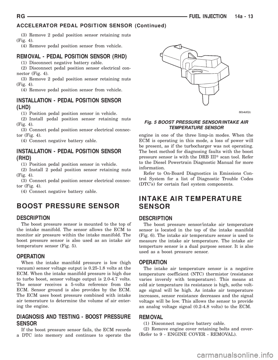
The boost pressure sensor is mounted to the top of
the intake manifold. The sensor allows the ECM to
monitor air pressure within the intake manifold. The
boost pressure sensor is also used as an intake air
temperature sensor (Fig. 5).
OPERATION
When the intake manifold pressure is low (high
vacuum) sensor voltage output is 0.25-1.8 volts at the
ECM. When the intake manifold pressure is high due
to turbo boost, sensor voltage output is 2.0-4.7 volts.
The sensor receives a 5-volts reference from the
ECM. Sensor ground is also provides by the ECM.
The ECM uses boost pressure combined with intake
air temerature to determine the volume of air enter-
ing the engine.
DIAGNOSIS AND TESTING - BOOST PRESSURE
SENSOR
If the boost pressure sensor fails, the ECM records
a DTC into memory and continues to operate theengine in one of the three limp-in modes. When the
ECM is operating in this mode, a loss of power will
be present, as if the turbocharger was not operating.
The best method for diagnosing faults with the boost
pressure sensor is with the DRB IIItscan tool. Refer
to the Diesel Powertrain Diagnostic Manual for more
information.
Refer to On-Board Diagnostics in Emissions Con-
trol System for a list of Diagnostic Trouble Codes
(DTC's) for certain fuel system components.
INTAKE AIR TEMPERATURE
SENSOR
DESCRIPTION
The boost pressure sensor/intake air temperature
sensor is located in the top of the intake manifold
(Fig. 6). The intake air temperature sensor is used to
measure the intake air temperature. The intake air
temperture sensor is a dual purpose sensor. It is also
used as a boost pressure sensor.
OPERATION
The intake air temperature sensor is a negative
temperature coefficient (NTC) thermistor (resistance
varies inversly with temperature). This means at
cold air temperature its resistance is high, sothe volt-
age signal will be high. As intake air temperature
increases, sensor resistance decreases and the signal
voltage will be low. This allows the sensor to provide
an analog voltage signal (0.2-4.8 volts) to the ECM.
REMOVAL
(1) Disconnect negative battery cable.
(2) Remove engine cover retaining bolts and cover-
(Refer to 9 - ENGINE COVER - REMOVAL).
Fig. 5 BOOST PRESSURE SENSOR/INTAKE AIR
TEMPERATURE SENSOR
RGFUEL INJECTION14a-13
ACCELERATOR PEDAL POSITION SENSOR (Continued)
Page 3173 of 4284
INSTALLATION
NOTE: If transaxle assembly has been replaced or
overhauled (clutch and/or seal replacement), it is
necessary to perfrom the TCM Quick Learn proce-
dure. (Refer to 8 - ELECTRICAL/ELECTRONIC CON-
TROL MODULES/TRANSMISSION CONTROL
MODULE - STANDARD PROCEDURE)
NOTE: If torque converter assembly has been
replaced, it is necessary to reset the TCC Break-In
Strategy. (Refer to 8 - ELECTRICAL/ELECTRONIC
CONTROL MODULES/TRANSMISSION CONTROL
MODULE - STANDARD PROCEDURE)
(1) Using a transmission jack and a helper, posi-
tion transaxle assembly to engine. Install and torque
bolts to 95 N´m (70 ft. lbs.).
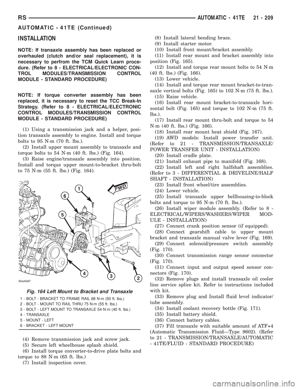
(2) Install upper mount assembly to transaxle and
torque bolts to 54 N´m (40 ft. lbs.) (Fig. 164).
(3) Raise engine/transaxle assembly into position.
Install and torque upper mount-to-bracket thru-bolt
to 75 N´m (55 ft. lbs.) (Fig. 164).
(4) Remove transmission jack and screw jack.
(5) Secure left wheelhouse splash shield.
(6) Install torque converter-to-drive plate bolts and
torque to 88 N´m (65 ft. lbs.)
(7) Install inspection cover.(8) Install lateral bending brace.
(9) Install starter motor.
(10) Install front mount/bracket assembly.
(11) Install rear mount and bracket assembly into
position (Fig. 165).
(12) Install and torque rear mount bolts to 54 N´m
(40 ft. lbs.) (Fig. 166).
(13) Lower vehicle.
(14) Install and torque rear mount bracket-to-tran-
saxle vertical bolts (Fig. 165) to 102 N´m (75 ft. lbs.).
(15) Raise vehicle.
(16) Install rear mount bracket-to-transaxle hori-
zontal bolt (Fig. 165) and torque to 102 N´m (75 ft.
lbs.).
(17) Install rear mount thru-bolt and torque to 54
N´m (40 ft. lbs.) (Fig. 166).
(18) Install rear mount heat shield (Fig. 167).
(19) AWD models: Install power transfer unit.
(Refer to 21 - TRANSMISSION/TRANSAXLE/
POWER TRANSFER UNIT - INSTALLATION)
(20) Install cradle plate.
(21) Install exhaust pipe to manifold (Fig. 168).
(22) Install left and right halfshaft assemblies.
(Refer to 3 - DIFFERENTIAL & DRIVELINE/HALF
SHAFT - INSTALLATION)
(23) Install front wheel/tire assemblies.
(24) Lower vehicle.
(25) Install transaxle upper bellhousing-to-block
bolts and torque to 95 N´m (70 ft. lbs.).
(26) Install wiper module assembly. (Refer to 8 -
ELECTRICAL/WIPERS/WASHERS/WIPER MOD-
ULE - INSTALLATION)
(27) Connect crank position sensor (if equipped).
(28) Connect gearshift cable to upper mount
bracket and transaxle manual valve lever (Fig. 169).
(29) Connect solenoid/pressure switch assembly
(Fig. 170).
(30) Connect transmission range sensor connector
(Fig. 170).
(31) Connect input and output speed sensor con-
nectors (Fig. 170).
(32) Remove plugs and install transaxle oil cooler
line service splice kit. Refer to instructions included
with kit.
(33) Remove plug and Install fluid level indicator/
tube assembly.
(34) Install coolant recovery bottle (Fig. 171).
(35) Install battery shield.
(36) Connect battery cables.
(37) Fill transaxle with suitable amount of ATF+4
(Automatic Transmission FluidÐType 9602). (Refer
to 21 - TRANSMISSION/TRANSAXLE/AUTOMATIC
- 41TE/FLUID - STANDARD PROCEDURE)
Fig. 164 Left Mount to Bracket and Transaxle
1 - BOLT - BRACKET TO FRAME RAIL 68 N´m (50 ft. lbs.)
2 - BOLT - MOUNT TO RAIL THRU 75 N´m (55 ft. lbs.)
3 - BOLT - LEFT MOUNT TO TRANSAXLE 54 N´m (40 ft. lbs.)
4 - TRANSAXLE
5 - MOUNT - LEFT
6 - BRACKET - LEFT MOUNT
RSAUTOMATIC - 41TE21 - 209
AUTOMATIC - 41TE (Continued)
Page 3198 of 4284
in 3rd and 4th gear Autostick mode. Speed control
will be deactivated if the transaxle is shifted to 2nd
gear. Shifting into OD position cancels the Autostick
mode, and the transaxle resumes the OD shift sched-
ule.
DRIVING CLUTCHES
DESCRIPTION
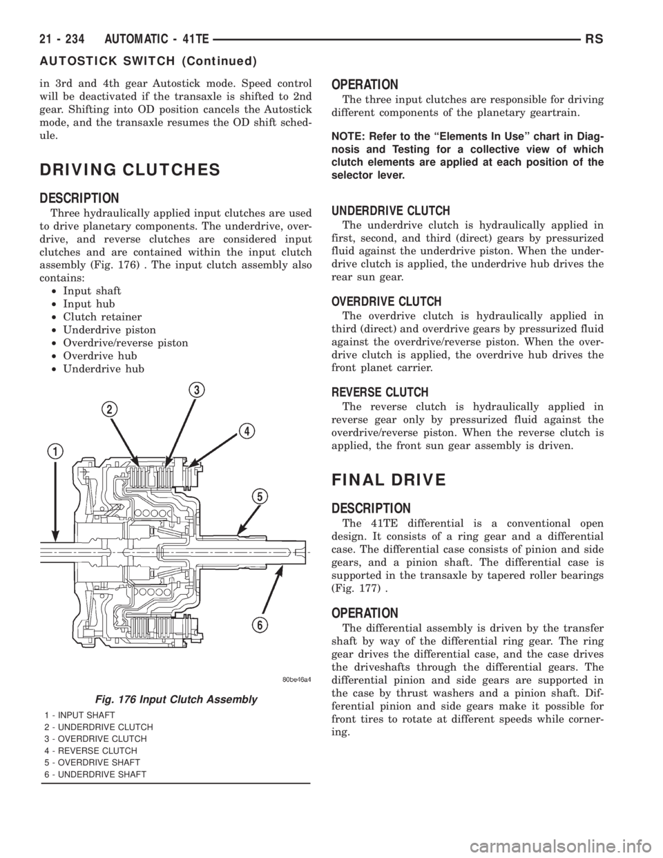
Three hydraulically applied input clutches are used
to drive planetary components. The underdrive, over-
drive, and reverse clutches are considered input
clutches and are contained within the input clutch
assembly (Fig. 176) . The input clutch assembly also
contains:
²Input shaft
²Input hub
²Clutch retainer
²Underdrive piston
²Overdrive/reverse piston
²Overdrive hub
²Underdrive hub
OPERATION
The three input clutches are responsible for driving
different components of the planetary geartrain.
NOTE: Refer to the ªElements In Useº chart in Diag-
nosis and Testing for a collective view of which
clutch elements are applied at each position of the
selector lever.
UNDERDRIVE CLUTCH
The underdrive clutch is hydraulically applied in
first, second, and third (direct) gears by pressurized
fluid against the underdrive piston. When the under-
drive clutch is applied, the underdrive hub drives the
rear sun gear.
OVERDRIVE CLUTCH
The overdrive clutch is hydraulically applied in
third (direct) and overdrive gears by pressurized fluid
against the overdrive/reverse piston. When the over-
drive clutch is applied, the overdrive hub drives the
front planet carrier.
REVERSE CLUTCH
The reverse clutch is hydraulically applied in
reverse gear only by pressurized fluid against the
overdrive/reverse piston. When the reverse clutch is
applied, the front sun gear assembly is driven.
FINAL DRIVE
DESCRIPTION
The 41TE differential is a conventional open
design. It consists of a ring gear and a differential
case. The differential case consists of pinion and side
gears, and a pinion shaft. The differential case is
supported in the transaxle by tapered roller bearings
(Fig. 177) .
OPERATION
The differential assembly is driven by the transfer
shaft by way of the differential ring gear. The ring
gear drives the differential case, and the case drives
the driveshafts through the differential gears. The
differential pinion and side gears are supported in
the case by thrust washers and a pinion shaft. Dif-
ferential pinion and side gears make it possible for
front tires to rotate at different speeds while corner-
ing.
Fig. 176 Input Clutch Assembly
1 - INPUT SHAFT
2 - UNDERDRIVE CLUTCH
3 - OVERDRIVE CLUTCH
4 - REVERSE CLUTCH
5 - OVERDRIVE SHAFT
6 - UNDERDRIVE SHAFT
21 - 234 AUTOMATIC - 41TERS
AUTOSTICK SWITCH (Continued)
Page 3228 of 4284
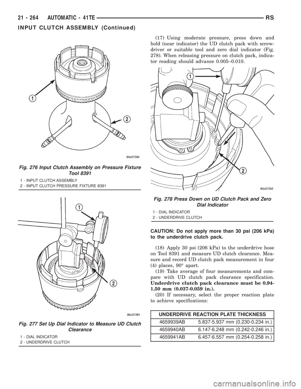
(17) Using moderate pressure, press down and
hold (near indicator) the UD clutch pack with screw-
driver or suitable tool and zero dial indicator (Fig.
278). When releasing pressure on clutch pack, indica-
tor reading should advance 0.005±0.010.
CAUTION: Do not apply more than 30 psi (206 kPa)
to the underdrive clutch pack.
(18) Apply 30 psi (206 kPa) to the underdrive hose
on Tool 8391 and measure UD clutch clearance. Mea-
sure and record UD clutch pack measurement in four
(4) places, 90É apart.
(19) Take average of four measurements and com-
pare with UD clutch pack clearance specification.
Underdrive clutch pack clearance must be 0.94-
1.50 mm (0.037-0.059 in.).
(20) If necessary, select the proper reaction plate
to achieve specifications:
UNDERDRIVE REACTION PLATE THICKNESS
4659939AB 5.837-5.937 mm (0.230-0.234 in.)
4659940AB 6.147-6.248 mm (0.242-0.246 in.)
4659941AB 6.457-6.557 mm (0.254-0.258 in.)
Fig. 276 Input Clutch Assembly on Pressure Fixture
Tool 8391
1 - INPUT CLUTCH ASSEMBLY
2 - INPUT CLUTCH PRESSURE FIXTURE 8391
Fig. 277 Set Up Dial Indicator to Measure UD Clutch
Clearance
1 - DIAL INDICATOR
2 - UNDERDRIVE CLUTCH
Fig. 278 Press Down on UD Clutch Pack and Zero
Dial Indicator
1 - DIAL INDICATOR
2 - UNDERDRIVE CLUTCH
21 - 264 AUTOMATIC - 41TERS
INPUT CLUTCH ASSEMBLY (Continued)
Page 3230 of 4284
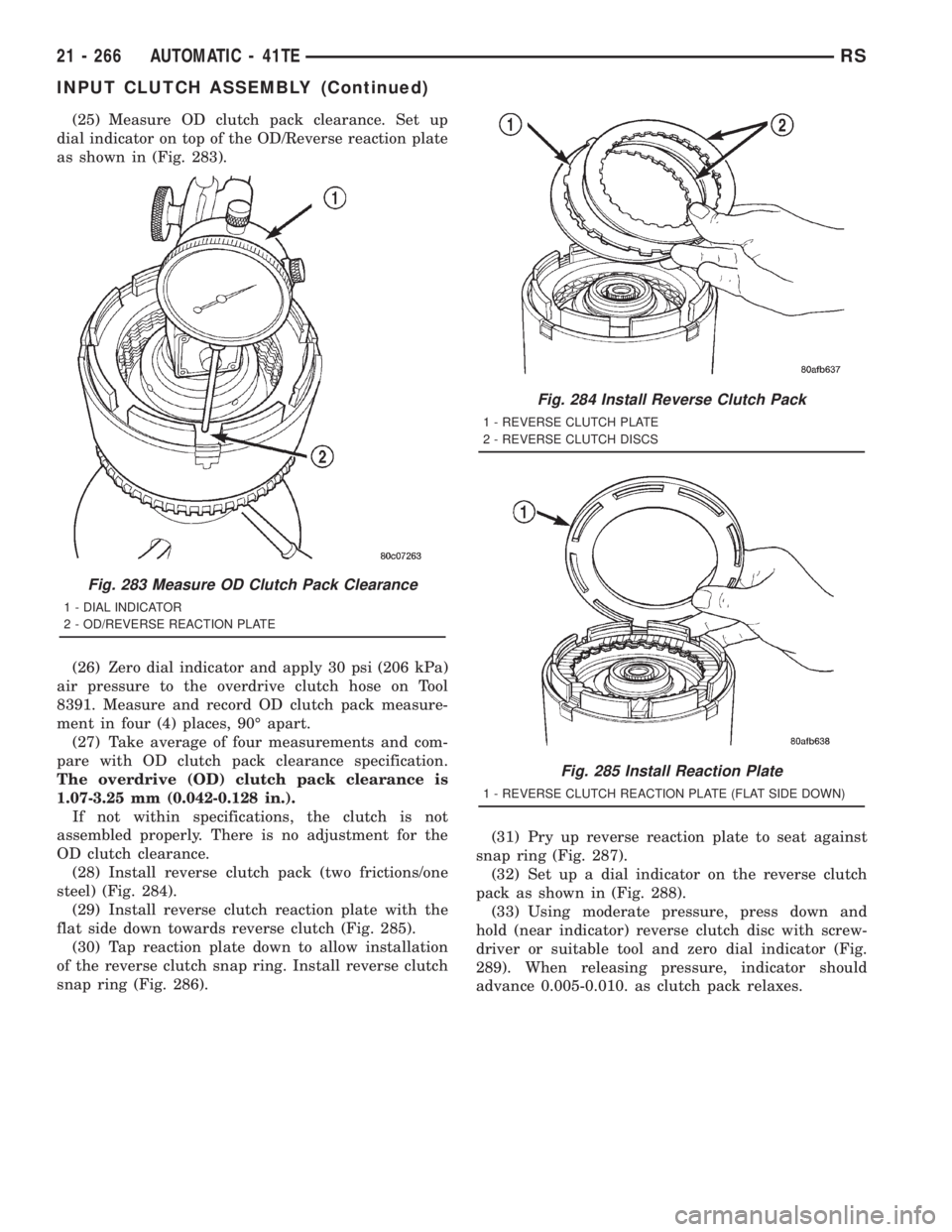
(25) Measure OD clutch pack clearance. Set up
dial indicator on top of the OD/Reverse reaction plate
as shown in (Fig. 283).
(26) Zero dial indicator and apply 30 psi (206 kPa)
air pressure to the overdrive clutch hose on Tool
8391. Measure and record OD clutch pack measure-
ment in four (4) places, 90É apart.
(27) Take average of four measurements and com-
pare with OD clutch pack clearance specification.
The overdrive (OD) clutch pack clearance is
1.07-3.25 mm (0.042-0.128 in.).
If not within specifications, the clutch is not
assembled properly. There is no adjustment for the
OD clutch clearance.
(28) Install reverse clutch pack (two frictions/one
steel) (Fig. 284).
(29) Install reverse clutch reaction plate with the
flat side down towards reverse clutch (Fig. 285).
(30) Tap reaction plate down to allow installation
of the reverse clutch snap ring. Install reverse clutch
snap ring (Fig. 286).(31) Pry up reverse reaction plate to seat against
snap ring (Fig. 287).
(32) Set up a dial indicator on the reverse clutch
pack as shown in (Fig. 288).
(33) Using moderate pressure, press down and
hold (near indicator) reverse clutch disc with screw-
driver or suitable tool and zero dial indicator (Fig.
289). When releasing pressure, indicator should
advance 0.005-0.010. as clutch pack relaxes.
Fig. 283 Measure OD Clutch Pack Clearance
1 - DIAL INDICATOR
2 - OD/REVERSE REACTION PLATE
Fig. 284 Install Reverse Clutch Pack
1 - REVERSE CLUTCH PLATE
2 - REVERSE CLUTCH DISCS
Fig. 285 Install Reaction Plate
1 - REVERSE CLUTCH REACTION PLATE (FLAT SIDE DOWN)
21 - 266 AUTOMATIC - 41TERS
INPUT CLUTCH ASSEMBLY (Continued)
Page 3303 of 4284
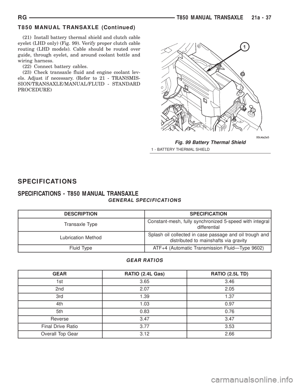
(21) Install battery thermal shield and clutch cable
eyelet (LHD only) (Fig. 99). Verify proper clutch cable
routing (LHD models). Cable should be routed over
guide, through eyelet, and around coolant bottle and
wiring harness.
(22) Connect battery cables.
(23) Check transaxle fluid and engine coolant lev-
els. Adjust if necessary. (Refer to 21 - TRANSMIS-
SION/TRANSAXLE/MANUAL/FLUID - STANDARD
PROCEDURE)
SPECIFICATIONS
SPECIFICATIONS - T850 MANUAL TRANSAXLE
GENERAL SPECIFICATIONS
DESCRIPTION SPECIFICATION
Transaxle TypeConstant-mesh, fully synchronized 5-speed with integral
differential
Lubrication MethodSplash oil collected in case passage and oil trough and
distributed to mainshafts via gravity
Fluid Type ATF+4 (Automatic Transmission FluidÐType 9602)
GEAR RATIOS
GEAR RATIO (2.4L Gas) RATIO (2.5L TD)
1st 3.65 3.46
2nd 2.07 2.05
3rd 1.39 1.37
4th 1.03 0.97
5th 0.83 0.76
Reverse 3.47 3.47
Final Drive Ratio 3.77 3.53
Overall Top Gear 3.12 2.66
Fig. 99 Battery Thermal Shield
1 - BATTERY THERMAL SHIELD
RGT850 MANUAL TRANSAXLE21a-37
T850 MANUAL TRANSAXLE (Continued)
Page 3321 of 4284
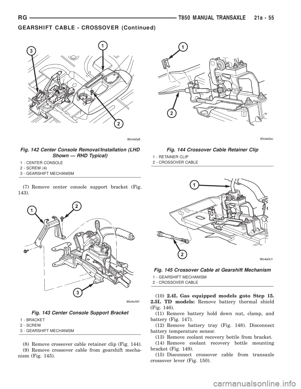
(7) Remove center console support bracket (Fig.
143).
(8) Remove crossover cable retainer clip (Fig. 144).
(9) Remove crossover cable from gearshift mecha-
nism (Fig. 145).(10)2.4L Gas equipped models goto Step 15.
2.5L TD models:Remove battery thermal shield
(Fig. 146).
(11) Remove battery hold down nut, clamp, and
battery (Fig. 147).
(12) Remove battery tray (Fig. 148). Disconnect
battery temperature sensor.
(13) Remove coolant recovery bottle from bracket.
(14) Remove coolant recovery bottle mounting
bracket (Fig. 149).
(15) Disconnect crossover cable from transaxle
crossover lever (Fig. 150).
Fig. 142 Center Console Removal/Installation (LHD
Shown Ð RHD Typical)
1 - CENTER CONSOLE
2 - SCREW (4)
3 - GEARSHIFT MECHANISM
Fig. 143 Center Console Support Bracket
1 - BRACKET
2 - SCREW
3 - GEARSHIFT MECHANISM
Fig. 144 Crossover Cable Retainer Clip
1 - RETAINER CLIP
2 - CROSSOVER CABLE
Fig. 145 Crossover Cable at Gearshift Mechanism
1 - GEARSHIFT MECHANISM
2 - CROSSOVER CABLE
RGT850 MANUAL TRANSAXLE21a-55
GEARSHIFT CABLE - CROSSOVER (Continued)