Page 165 of 4770

CRANKSHAFT INSPECTION AND REPAIR
1. INSPECT CRANKSHAFT FOR RUNOUT
(a) Place the crankshaft on V±blocks.
(b) Using a dial indicator, measure the circle runout at the
center journal.
Maximum circle runout:
0.06 mm (0.0024 In.)
If the circle runout is greater than maximum, replace
the crankshaft.
2. INSPECT MAIN JOURNALS AND CRANK PINS
(a) Using a micrometer, measure the diameter of each
main journal and crank pin.
Main journal diameter:
STD size
54.988 ± 55.003 mm (2.1653±2.1655 in.)
U/S 0.25
54.745 ± 54.755 mm (2.1553±2.1557 in.)
Crank pin diameter:
STD size
51.985 ± 52.000 mm (2.0466±2.0472 in.)
U/S 0.25
51.745 ± 51.755 mm (2.0372±2.0376 in.)
If the diameter is not as specified, check the oil clear±
ance (See pages EG1±98 to 104). If necessary, grind
or replace the crankshaft.
(b) Check each main journal and crank pin for taper and
out±of±round as shown.
Maximum taper and out±of±round:
0.02 mm (0.0008 in.)
If the taper and out±of±round is greater than maxi±
mum, replace the crankshaft.
3. IF NECESSARY. GRIND AND HONE MAIN JOUR±
NALS AND/OR CRANK PINS
Grind and hone the main journals and/or crank pins to
the finished undersized diameter (See procedure in
step 2).
Install new main journal and/or crankshaft pin under±
sized bearings.
± 5S±FE ENGINEENGINE MECHANICALEG1±115
Page 166 of 4770
B. If oil pump is installed to the cylinder block:
(a) Using a knife, cut off the oil seal lip.
(b) Using a screwdriver, pry out the oil seal.
NOTICE: Be careful not to damage the crankshaft. Tape
the screwdriver tip.
CRANKSHAFT OIL SEALS
REPLACEMENT
HINT: There are 2 methods (A and B) to replace the oil
seal which are as follows:
(b) Using SST and a hammer, tap in a new oil seal until its
surface is flush with the oil pump case edge.
SST 09223 ± 63010
(c) Apply MP grease to the oil seal lip. 1. REPLACE CRANKSHAFT FRONT OIL SEAL
A. If oil pump is removed from cylinder block:
(a) Using a screwdriver and a hammer, tap out the oil
seal.
(c) Apply MP grease to a new oil seal lip.
(d) Using SST and a hammer, tap in the oil seal until its
surface is flush with the oil pump case edge.
SST 09226 ±10010
± 5S±FE ENGINEENGINE MECHANICALEG1±116
Page 167 of 4770
(b) Using SST and a hammer, tap in a new oil seal until its
surface is flush with the rear oil seal edge.
SST 09223±63010
(c) Apply MP grease to the oil seal lip.
B. If rear oil seal retainer Is installed to cylinder block:
(a) Using a knife, cut off the oil seal lip.
(b) Using a screwdriver, pry out the oil seal.
NOTICE: Be careful not to damage the crankshaft. Tape
the screwdriver tip.
2. REPLACE CRANKSHAFT REAR OIL SEAL
A. If rear oil seal retainer is removed from cylinder
block:
(a) Using screwdriver and hammer, tap out the oil seal.
(c) Apply MP grease to a new oil seal lip.
(d) Using SST and a hammer, tap in the oil seal until its
surface is flush with the rear oil seal retainer edge.
SST 09223 ± 63010
± 5S±FE ENGINEENGINE MECHANICALEG1±117
Page 168 of 4770
PISTON AND CONNECTING ROD
ASSEMBLY
1. ASSEMBLE PISTON AND CONNECTING ROD
(a) Install a new snap ring on one side of the piston pin
hole.
(c) Coat the piston pin with engine oil.
(d) Align the front marks of the piston and connecting
rod, and push in the piston pin with your thumb.
(e) Install a new snap ring on the other side of the piston
pin hole.
2. INSTALL PISTON RINGS
(a) Install the oil ring expander and 2 side rails by hand.(b) Gradually heat the piston to 80±90�C
(176±194�F).
± 5S±FE ENGINEENGINE MECHANICALEG1±118
Page 169 of 4770

CYLINDER BLOCK ASSEMBLY
(See Components for Cylinder Block Disassembly and
Assembly)
HINT:
wThoroughly clean all parts to be assembled.
wBefore installing the parts, apply new engine oil
to all sliding and rotating surfaces.
wReplace all gaskets, 0±rings and oil seals with
new parts.
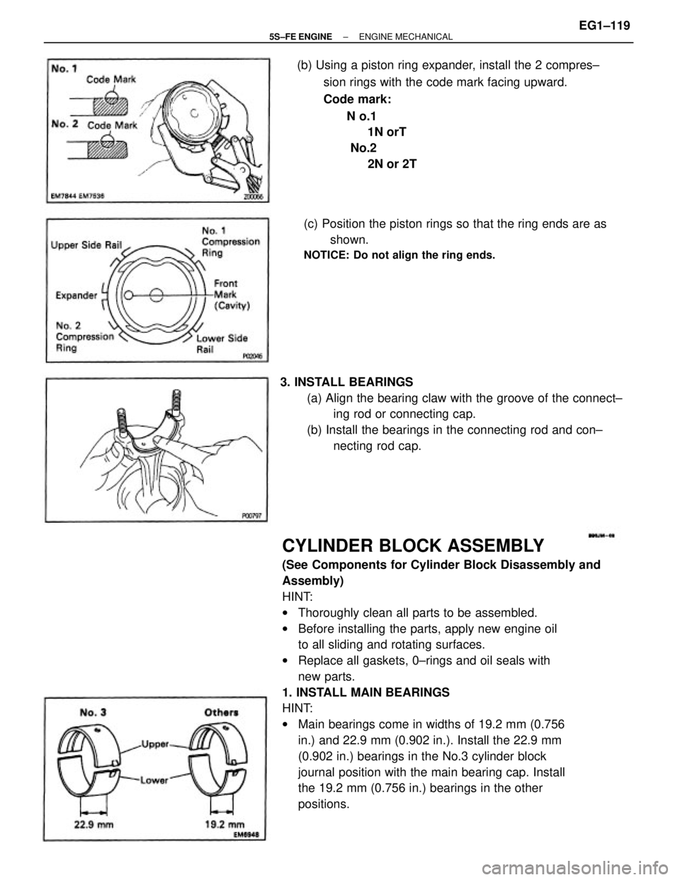
1. INSTALL MAIN BEARINGS
HINT:
wMain bearings come in widths of 19.2 mm (0.756
in.) and 22.9 mm (0.902 in.). Install the 22.9 mm
(0.902 in.) bearings in the No.3 cylinder block
journal position with the main bearing cap. Install
the 19.2 mm (0.756 in.) bearings in the other
positions. (b) Using a piston ring expander, install the 2 compres±
sion rings with the code mark facing upward.
Code mark:
N o.1
1N orT
No.2
2N or 2T
3. INSTALL BEARINGS
(a) Align the bearing claw with the groove of the connect±
ing rod or connecting cap.
(b) Install the bearings in the connecting rod and con±
necting rod cap. (c) Position the piston rings so that the ring ends are as
shown.
NOTICE: Do not align the ring ends.
± 5S±FE ENGINEENGINE MECHANICALEG1±119
Page 170 of 4770
(b) Align the bearing claw with the claw groove of the
main bearing cap, and push in the 5 lower bearings.
HINT: A number is marked on each main bearing cap
to indicate the installation position.
2. INSTALL UPPER THRUST WASHERS
Install the 2 thrust washers under the No.3 journal
position of the cylinder block with the oil grooves
facing outward.(a) Align the bearing claw with the claw groove of the
cylinder block, and push in the 5 upper bearings. wUpper bearings have an oil groove and oil holes;
lower bearings do not.
3. PLACE CRANKSHAFT ON CYLINDER BLOCK
± 5S±FE ENGINEENGINE MECHANICALEG1±120
Page 171 of 4770

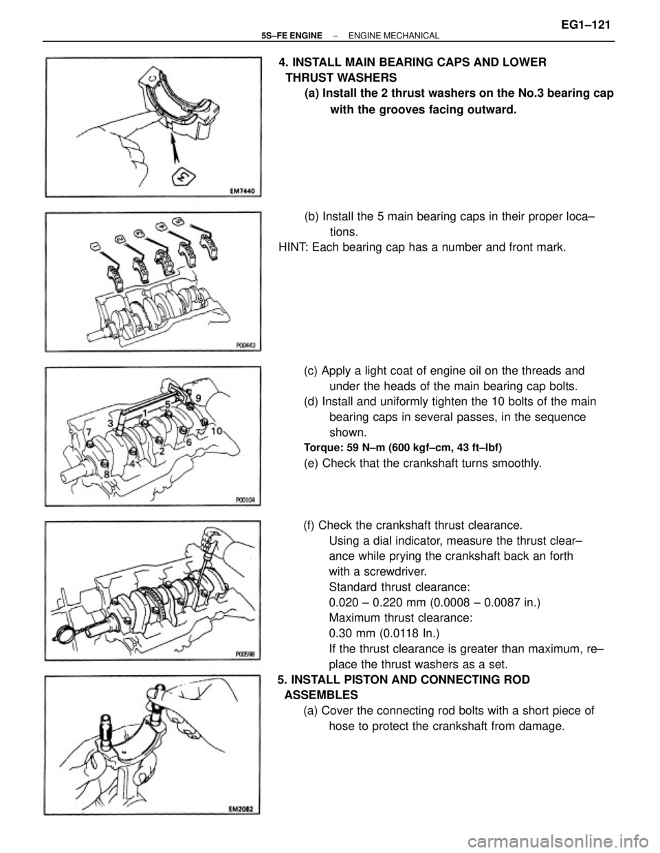
(f) Check the crankshaft thrust clearance.
Using a dial indicator, measure the thrust clear±
ance while prying the crankshaft back an forth
with a screwdriver.
Standard thrust clearance:
0.020 ± 0.220 mm (0.0008 ± 0.0087 in.)
Maximum thrust clearance:
0.30 mm (0.0118 In.)
If the thrust clearance is greater than maximum, re±
place the thrust washers as a set.
5. INSTALL PISTON AND CONNECTING ROD
ASSEMBLES
(a) Cover the connecting rod bolts with a short piece of
hose to protect the crankshaft from damage. (c) Apply a light coat of engine oil on the threads and
under the heads of the main bearing cap bolts.
(d) Install and uniformly tighten the 10 bolts of the main
bearing caps in several passes, in the sequence
shown.
Torque: 59 N±m (600 kgf±cm, 43 ft±lbf)
(e) Check that the crankshaft turns smoothly. 4. INSTALL MAIN BEARING CAPS AND LOWER
THRUST WASHERS
(a) Install the 2 thrust washers on the No.3 bearing cap
with the grooves facing outward.
(b) Install the 5 main bearing caps in their proper loca±
tions.
HINT: Each bearing cap has a number and front mark.
± 5S±FE ENGINEENGINE MECHANICALEG1±121
Page 172 of 4770

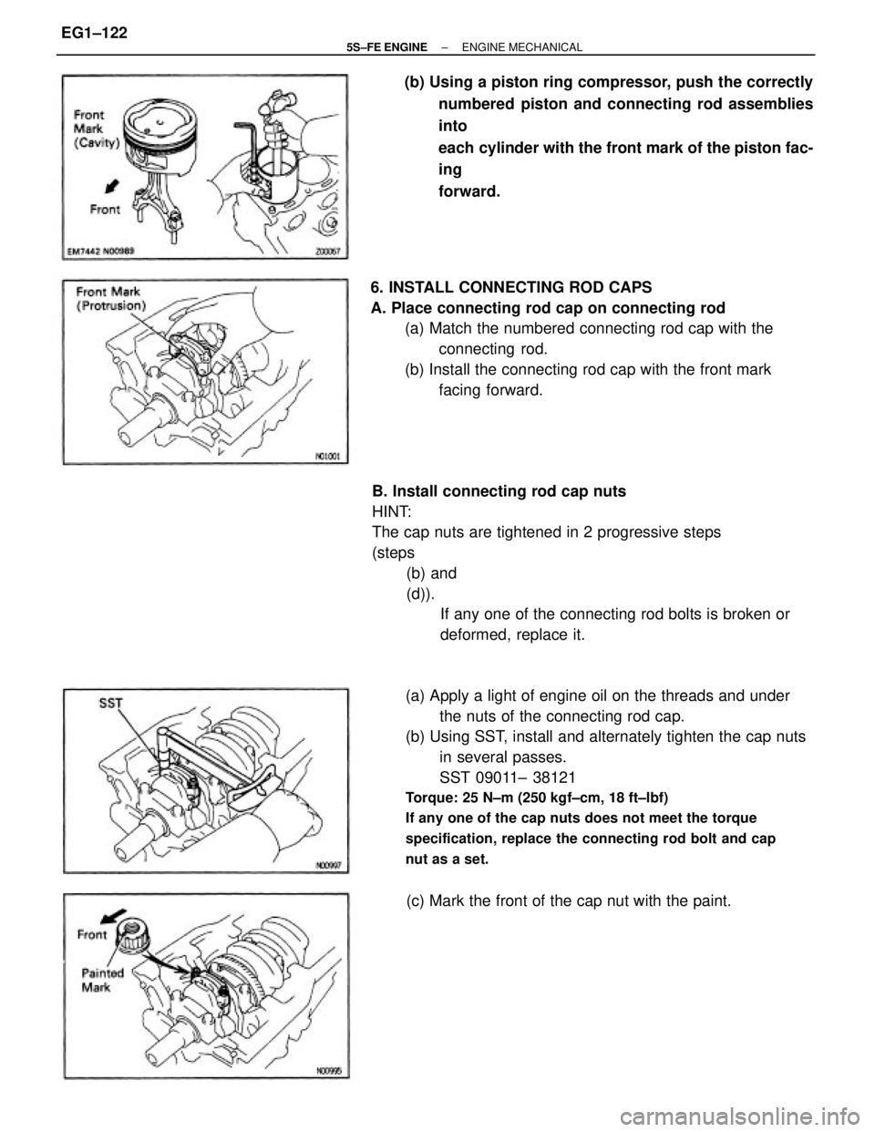
(a) Apply a light of engine oil on the threads and under
the nuts of the connecting rod cap.
(b) Using SST, install and alternately tighten the cap nuts
in several passes.
SST 09011± 38121
Torque: 25 N±m (250 kgf±cm, 18 ft±lbf)
If any one of the cap nuts does not meet the torque
specification, replace the connecting rod bolt and cap
nut as a set.
B. Install connecting rod cap nuts
HINT:
The cap nuts are tightened in 2 progressive steps
(steps
(b) and
(d)).
If any one of the connecting rod bolts is broken or
deformed, replace it. 6. INSTALL CONNECTING ROD CAPS
A. Place connecting rod cap on connecting rod
(a) Match the numbered connecting rod cap with the
connecting rod.
(b) Install the connecting rod cap with the front mark
facing forward. (b) Using a piston ring compressor, push the correctly
numbered piston and connecting rod assemblies
into
each cylinder with the front mark of the piston fac-
ing
forward.
(c) Mark the front of the cap nut with the paint.
± 5S±FE ENGINEENGINE MECHANICALEG1±122