Page 3434 of 4770

EM08A±04
A07356
A07357
P03267
P03268
P03149
EM±42
± ENGINE MECHANICAL (5S±FE)CYLINDER HEAD
1214 Author�: Date�:
INSPECTION
1. CLE AN TO P SURFACE S OF PIS TO NS AND CY L-
INDER BLOCK
(a) Turn the crankshaft, and bring each piston to top dead
center (TDC). Using a gasket scraper, remove all the car-
bon from the piston top surface.
(b) Using a gasket scraper, remove all the gasket material
from the cylinder block surface.
(c) Using compressed air, blow carbon and oil from the bolt
holes.
CAUTION:
Protect your eyes when using high±pressure compressed
air.
2. INSPECT TOP SURFACE OF CYLINDER BLOCK FOR
FLATNESS (See page EM±97)
3. CLEAN CYLINDER HEAD
(a) Using a gasket scraper, remove all the gasket material
from the cylinder block contact surface.
NOTICE:
Be careful not to scratch the cylinder block contact sur-
face.
(b) Using a wire brush, remove all the carbon from the com-
bustion chamber.
NOTICE:
Be careful not to scratch the cylinder block contact sur-
face.
(c) Using a valve guide bushing brush and solvent, clean all
the guide bushings.
Page 3456 of 4770
EM0YV±01
A02195
Radiator Reservoir Hose
Generator Drive BeltUpper Radiator
Hose
Support BracketFront Exhaust Pipe PS Oil Pressure Switch
ConnectorBattery TrayBattery
PS Pump Drive Belt
PS Pump
Support Stay Upper Radiator Support
Lower Radiator Hose
A/C Compressor
Cylinder Block Insulator
LH Front Fender Apron Seal
Oil Cooler Hose (A/T)
Cruise Control ActuatorEVAP Hose
Air Filter Upper Radiator
Support
EVAP Hose Hood
PCV Hose
Support
Bracket � Gasket
�
� Non±reusable part� Gasket
�Clamp
N´m (kgf´cm, ft´lbf)
62 (630, 46)
56 (570, 41)
�
: Specified torque
Washer Hose
for Windshield
No.1 Electric
Cooling Fan
Connector
ECT Switch
Connector No.2 Electric
Cooling Fan
ConnectorRadiator
Assembly
A/C Compressor
ConnectorLower Radiator
Support
RH Front Fender
Aplon Seal
Cruise
Control
Actuator
Connector
Battery
Hold±Down
ClampAir Cleaner
Case
VSV
Connector
for EVAP
EVAP
Hose
IAT Sensor
Connector
Air
Cleaner
Cap
EM±64
± ENGINE MECHANICAL (5S±FE)ENGINE UNIT
1236 Author�: Date�:
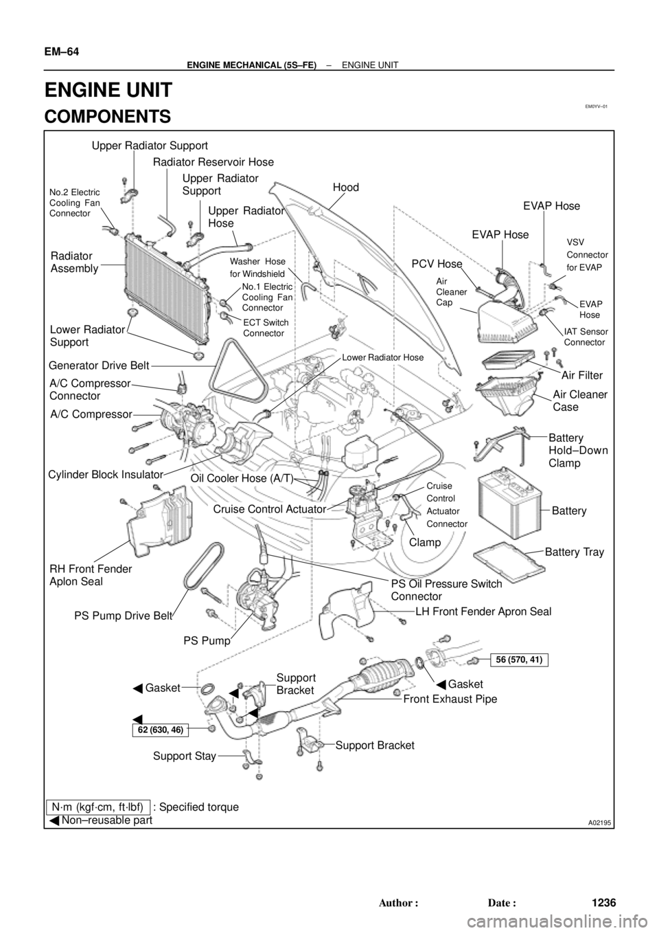
ENGINE UNIT
COMPONENTS
Page 3509 of 4770
EM04J±03
P19471Compression Gauge
± ENGINE MECHANICAL (1MZ±FE)COMPRESSION
EM±3
1289 Author�: Date�:
COMPRESSION
INSPECTION
HINT:
If there is lack of power, excessive oil consumption or poor fuel
economy, measure the compression pressure.
1. WARM UP AND STOP ENGINE
Allow the engine to warm up to normal operating temperature.
2. REMOVE IGNITION COILS AND HIGH±TENSION
CORDS (See page IG±7)
3. REMOVE SPARK PLUGS
Using a 16 mm plug wrench, remove the 6 spark plugs.
4. CHECK CYLINDER COMPRESSION PRESSURE
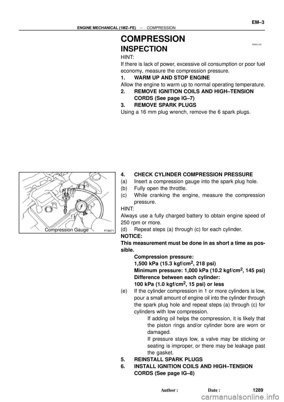
(a) Insert a compression gauge into the spark plug hole.
(b) Fully open the throttle.
(c) While cranking the engine, measure the compression
pressure.
HINT:
Always use a fully charged battery to obtain engine speed of
250 rpm or more.
(d) Repeat steps (a) through (c) for each cylinder.
NOTICE:
This measurement must be done in as short a time as pos-
sible.
Compression pressure:
1,500 kPa (15.3 kgf/cm
2, 218 psi)
Minimum pressure: 1,000 kPa (10.2 kgf/cm
2, 145 psi)
Difference between each cylinder:
100 kPa (1.0 kgf/cm
2, 15 psi) or less
(e) If the cylinder compression in 1 or more cylinders is low,
pour a small amount of engine oil into the cylinder through
the spark plug hole and repeat steps (a) through (c) for
cylinders with low compression.
�If adding oil helps the compression, it is likely that
the piston rings and/or cylinder bore are worn or
damaged.
�If pressure stays low, a valve may be sticking or
seating is improper, or there may be leakage past
the gasket.
5. REINSTALL SPARK PLUGS
6. INSTALL IGNITION COILS AND HIGH±TENSION
CORDS (See page IG±8)
Page 3529 of 4770
A02338
5th4th3rd
2nd
6th
1st
A05064
1.27 mm
Hexagon
Wrench
A05065
A05066
1.27 mm
Hexagon
Wrench
± ENGINE MECHANICAL (1MZ±FE)TIMING BELT
EM±23
1309 Author�: Date�:
7. INSTALL TIMING BELT
NOTICE:
The engine should be cold.
(a) Remove any oil or water on the pulleys, and keep them
clean.
NOTICE:
Only wipe the pulleys; do not use any cleansing agent.
(b) Face the front mark on the timing belt forward.
(c) Align the installation mark on the timing belt with the tim-
ing mark of the crankshaft timing pulley.
(d) Align the installation marks on the timing belt with the tim-
ing marks of the camshaft timing pulleys.
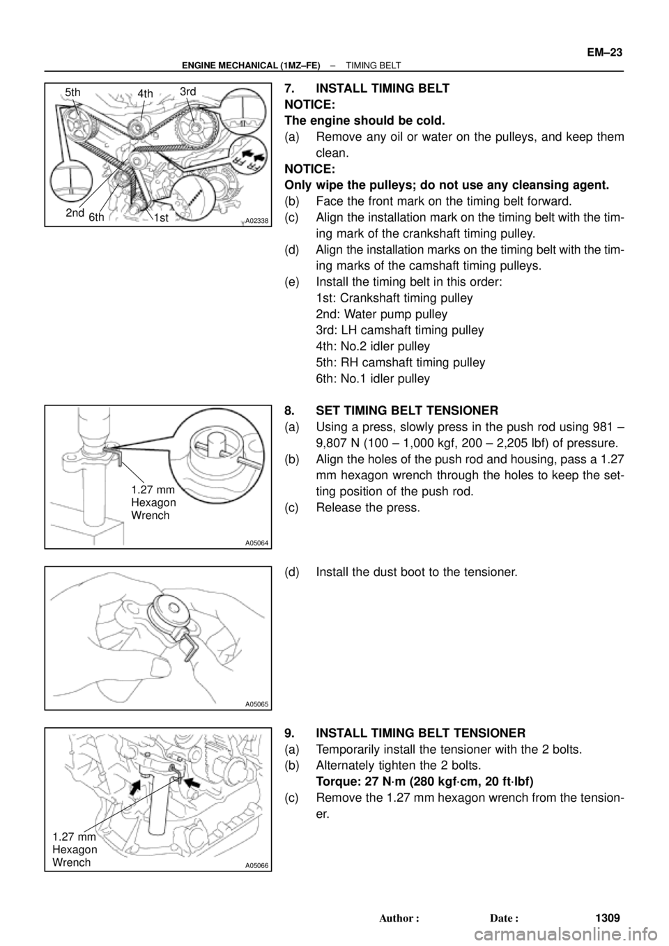
(e) Install the timing belt in this order:
1st: Crankshaft timing pulley
2nd: Water pump pulley
3rd: LH camshaft timing pulley
4th: No.2 idler pulley
5th: RH camshaft timing pulley
6th: No.1 idler pulley
8. SET TIMING BELT TENSIONER
(a) Using a press, slowly press in the push rod using 981 ±
9,807 N (100 ± 1,000 kgf, 200 ± 2,205 lbf) of pressure.
(b) Align the holes of the push rod and housing, pass a 1.27
mm hexagon wrench through the holes to keep the set-
ting position of the push rod.
(c) Release the press.
(d) Install the dust boot to the tensioner.
9. INSTALL TIMING BELT TENSIONER
(a) Temporarily install the tensioner with the 2 bolts.
(b) Alternately tighten the 2 bolts.
Torque: 27 N´m (280 kgf´cm, 20 ft´lbf)
(c) Remove the 1.27 mm hexagon wrench from the tension-
er.
Page 3549 of 4770
EM0YP±01
P12689
P12492
P12700
P12701
P12703
± ENGINE MECHANICAL (1MZ±FE)CYLINDER HEAD
EM±43
1329 Author�: Date�:
INSPECTION
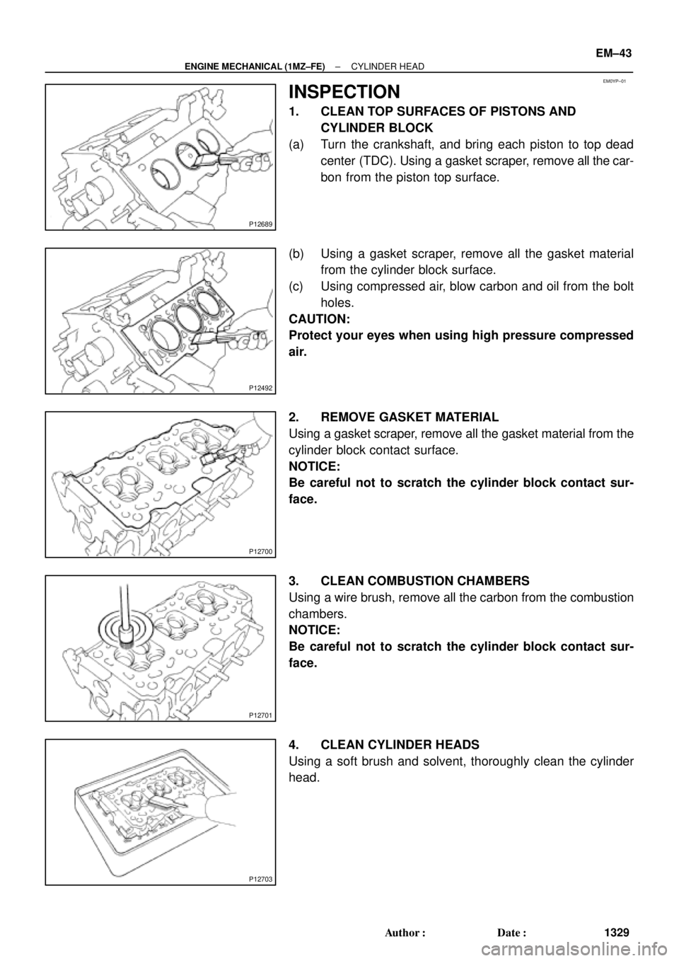
1. CLEAN TOP SURFACES OF PISTONS AND
CYLINDER BLOCK
(a) Turn the crankshaft, and bring each piston to top dead
center (TDC). Using a gasket scraper, remove all the car-
bon from the piston top surface.
(b) Using a gasket scraper, remove all the gasket material
from the cylinder block surface.
(c) Using compressed air, blow carbon and oil from the bolt
holes.
CAUTION:
Protect your eyes when using high pressure compressed
air.
2. REMOVE GASKET MATERIAL
Using a gasket scraper, remove all the gasket material from the
cylinder block contact surface.
NOTICE:
Be careful not to scratch the cylinder block contact sur-
face.
3. CLEAN COMBUSTION CHAMBERS
Using a wire brush, remove all the carbon from the combustion
chambers.
NOTICE:
Be careful not to scratch the cylinder block contact sur-
face.
4. CLEAN CYLINDER HEADS
Using a soft brush and solvent, thoroughly clean the cylinder
head.
Page 3650 of 4770

S05308
16 mm Plug
Wrench
P20584
IG0152
B06373
Ohmmeter
± IGNITION (5S±FE)IGNITION SYSTEM
IG±3
1685 Author�: Date�:
(c) Using a 16 mm plug wrench, remove the 4 spark plugs.
(d) Visually check the spark plug for thread damage and insu-
lator damage.
If abnormal, replace the spark plug.
Recommended spark plug:
DENSO madePK20TR11
NGK madeBKR6EKPB11
(e) Inspect the electrode gaps.
Maximum electrode gap for used spark plug:
1.3 mm (0.051 in.)
If the gap is greater than maximum, replace the spark plug.
Correct electrode gap for new spark plug:
1.1 mm (0.043 in.)
NOTICE:
If adjusting the gap of a new spark plug, bend only the base
of the ground electrode. Do not touch the tip. Never attempt
to adjust the gap on the used plug.
(f) Clean the spark plugs.
If the electrode has traces of wet carbon, allow it to dry and then
clean with a spark plug cleaner.
Air pressure: Below 588 kPa (6 kgf/cm
2, 85 psi)
Duration: 20 seconds or less
HINT:
If there are traces of oil, remove it with gasoline before using the
spark plug cleaner.
(g) Using a 16 mm plug wrench, install the 4 spark plugs.
Torque: 18 N´m (180 kgf´cm, 13 ft´lbf)
(h) Reconnect the high±tension cords from the spark plugs.
4. INSPECT IGNITION COILS WITH IGNITERS
(a) Disconnect the high±tension cords from the ignition coils.
(b) Inspect the secondary coil resistance.
Using an ohmmeter, measure the resistance between the
high±tension terminals.
Secondary coil resistance:
Cold9.7 ± 16.7 kW
Hot12.4 ± 19.6 kW
Page 3663 of 4770

P13225
16 mm Plug
Wrench
P25746
DENSO PK20TR11 NGK BKR6EKPB11
P20584
IG0152
± IGNITION (1MZ±FE)IGNITION SYSTEM
IG±5
1699 Author�: Date�:
(e) Using a 16 mm plug wrench, remove the 6 spark plugs
from the RH and LH cylinder heads.
(f) Check the spark plug for thread damage and insulator
damage.
If abnormal, replace the spark plug.
Recommended spark plug:
DENSO madePK20TR11
NGK madeBKR6EKPB11
(g) Inspect the electrode gaps.
Maximum electrode gap for used spark plug:
1.3 mm (0.051 in.)
If the gap is greater than maximum, replace the spark plug.
Correct electrode gap for new spark plug:
1.1 mm (0.043 in.)
NOTICE:
If adjusting the gap of a new spark plug, bend only the base
of the ground electrode. Do not touch the tip. Never attempt
to adjust the gap on the used plug.
(h) Clean the spark plugs.
If the electrode has traces of wet carbon, allow it to dry and then
clean with a spark plug cleaner.
Air pressure: Below 588 kPa (6 kgf/cm
2, 85 psi)
Duration: 20 seconds or less
HINT:
If there are traces of oil, remove it with gasoline before using the
spark plug cleaner.
(i) Using a 16 mm plug wrench, install the 6 spark plugs to
the RH and LH cylinder heads.
Torque: 18 N´m (180 kgf´cm, 13 ft´lbf)
(j) Install the ignition coils.
(k) Install the high±tension cords set. (See step 2)
4. INSPECT IGNITION COILS
(a) Disconnect the high±tension cords from the ignition coils.
(b) Disconnect the ignition coil connectors.
Page 3715 of 4770
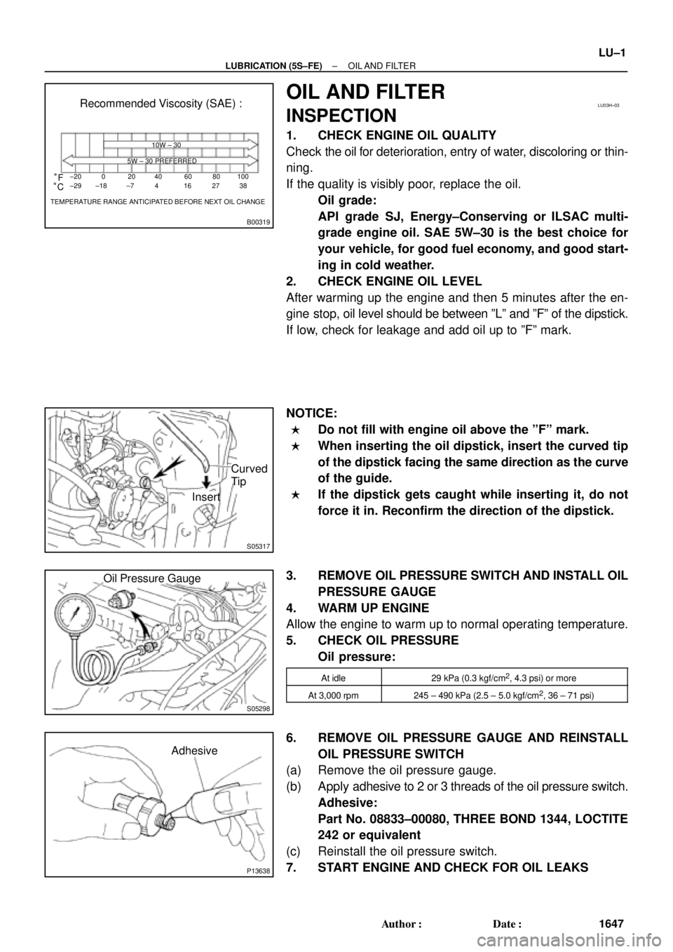
B00319
Recommended Viscosity (SAE) :
TEMPERATURE RANGE ANTICIPATED BEFORE NEXT OIL CHANGE 10W ± 30
5W ± 30 PREFERRED
±20
°C °F020406080
±29 ±18 ±7 4 16 27100
38
LU03H±03
S05317
Curved
Tip
Insert
S05298
Oil Pressure Gauge
P13638
Adhesive
± LUBRICATION (5S±FE)OIL AND FILTER
LU±1
1647 Author�: Date�:
OIL AND FILTER
INSPECTION
1. CHECK ENGINE OIL QUALITY
Check the oil for deterioration, entry of water, discoloring or thin-
ning.
If the quality is visibly poor, replace the oil.
Oil grade:
API grade SJ, Energy±Conserving or ILSAC multi-
grade engine oil. SAE 5W±30 is the best choice for
your vehicle, for good fuel economy, and good start-
ing in cold weather.
2. CHECK ENGINE OIL LEVEL
After warming up the engine and then 5 minutes after the en-
gine stop, oil level should be between ºLº and ºFº of the dipstick.
If low, check for leakage and add oil up to ºFº mark.
NOTICE:
�Do not fill with engine oil above the ºFº mark.
�When inserting the oil dipstick, insert the curved tip
of the dipstick facing the same direction as the curve
of the guide.
�If the dipstick gets caught while inserting it, do not
force it in. Reconfirm the direction of the dipstick.
3. REMOVE OIL PRESSURE SWITCH AND INSTALL OIL
PRESSURE GAUGE
4. WARM UP ENGINE
Allow the engine to warm up to normal operating temperature.
5. CHECK OIL PRESSURE
Oil pressure:
At idle29 kPa (0.3 kgf/cm2, 4.3 psi) or more
At 3,000 rpm245 ± 490 kPa (2.5 ± 5.0 kgf/cm2, 36 ± 71 psi)
6. REMOVE OIL PRESSURE GAUGE AND REINSTALL
OIL PRESSURE SWITCH
(a) Remove the oil pressure gauge.
(b) Apply adhesive to 2 or 3 threads of the oil pressure switch.
Adhesive:
Part No. 08833±00080, THREE BOND 1344, LOCTITE
242 or equivalent
(c) Reinstall the oil pressure switch.
7. START ENGINE AND CHECK FOR OIL LEAKS