Page 2389 of 4770
CO03F±03
P12487
± COOLING (1MZ±FE)WATER PUMP
CO±7
1615 Author�: Date�:
INSPECTION
1. INSPECT WATER PUMP
(a) Visually check the drain hole for coolant leakage.
If leakage is found, replace the water pump.
(b) Turn the pulley, and check that the water pump bearing
moves smoothly and quietly.
If necessary, replace the water pump.
2. INSPECT TIMING BELT COMPONENTS
(See page EM±19)
Page 2390 of 4770
CO0SO±01
P12942
CO±8
± COOLING (1MZ±FE)WATER PUMP
1616 Author�: Date�:
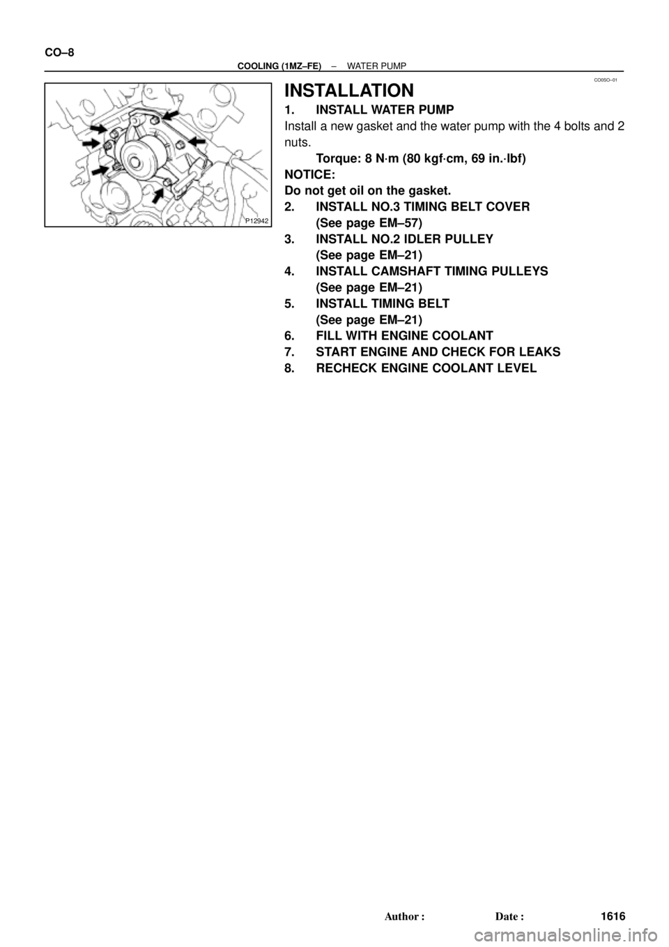
INSTALLATION
1. INSTALL WATER PUMP
Install a new gasket and the water pump with the 4 bolts and 2
nuts.
Torque: 8 N´m (80 kgf´cm, 69 in.´lbf)
NOTICE:
Do not get oil on the gasket.
2. INSTALL NO.3 TIMING BELT COVER
(See page EM±57)
3. INSTALL NO.2 IDLER PULLEY
(See page EM±21)
4. INSTALL CAMSHAFT TIMING PULLEYS
(See page EM±21)
5. INSTALL TIMING BELT
(See page EM±21)
6. FILL WITH ENGINE COOLANT
7. START ENGINE AND CHECK FOR LEAKS
8. RECHECK ENGINE COOLANT LEVEL
Page 3396 of 4770

(d) (e)
S05590
Turn
P03443
1 11 122
33 EM±4
± ENGINE MECHANICAL (5S±FE)VALVE CLEARANCE
1176 Author�: Date�:
VALVE CLEARANCE
INSPECTION
HINT:
Inspect and adjust the valve clear")
EM07Z±03
S05289
(c)
(d) (e)
S05590
Turn
P03443
1 11 122
33 EM±4
± ENGINE MECHANICAL (5S±FE)VALVE CLEARANCE
1176 Author�: Date�:
VALVE CLEARANCE
INSPECTION
HINT:
Inspect and adjust the valve clearance when the engine is cold.
1. REMOVE CYLINDER HEAD COVER
(a) Disconnect the 4 high±tension cords from the clamps on
the cylinder head cover.
(b) Disconnect the 4 high±tension cords from the spark
plugs.
(c) Disconnect the PCV hose from the intake manifold.
(d) Disconnect the PCV hose from the cylinder head cover.
(e) Disconnect the engine wire clamp from the mounting bolt
of the No.2 timing belt cover.
(f) Remove the cylinder head cover. (See page EM±33)
2. SET NO.1 CYLINDER TO TDC/COMPRESSION
(a) Turn the crankshaft pulley, and align its groove with timing
mark º0º of the No.1 timing belt cover.
(b) Check that the valve lifters on the No.1 cylinder are loose
and valve lifters on the No.4 are tight.
If not, turn the crankshaft one revolution (360°) and align the
mark as above.
3. INSPECT VALVE CLEARANCE
(a) Check only the valves indicated.
(1) Using a feeler gauge, measure the clearance be-
tween the valve lifter and camshaft.
(2) Record the out±of±specification valve clearance
measurements. They will be used later to determine
the required replacement adjusting shim.
Valve clearance (Cold):
Intake0.19 ± 0.29 mm (0.007 ± 0.011 in.)
Exhaust0.28 ± 0.38 mm (0.011 ± 0.015 in.)
(b) Turn the crankshaft one revolution (360°) and align the
mark as above.
Page 3398 of 4770

SST (B)
S05289
(b)
(c)
(d) EM±6
± ENGINE MECHANICAL (5S±FE)VALVE CLEARANCE
1178 Author�: Date�:
Exhaust: N = T + (A ± 0.33 mm (0.013 in.))
(3) Select a new shim with a thickness as")
P13989
SST (A)
SST (B)
S05289
(b)
(c)
(d) EM±6
± ENGINE MECHANICAL (5S±FE)VALVE CLEARANCE
1178 Author�: Date�:
Exhaust: N = T + (A ± 0.33 mm (0.013 in.))
(3) Select a new shim with a thickness as close as pos-
sible to the calculated value.
HINT:
Shims are available in 17 sizes in increments of 0.05 mm
(0.0020 in.), from 2.50 mm (0.0984 in.) to 3.30 mm (0.1299 in.).
(c) Install a new adjusting shim.
(1) Place a new adjusting shim on the valve lifter.
(2) Using SST (A), press down the valve lifter and re-
move SST (B).
SST 09248±55040 (09248±05410, 09248±05420)
(d) Recheck the valve clearance.
5. REINSTALL CYLINDER HEAD COVER
(a) Install the cylinder head cover. (See page EM±53)
(b) Connect the PCV hose to the intake manifold.
(c) Connect the PCV hose to the cylinder head cover.
(d) Install the engine wire clamp to the mounting bolt of the
No.2 timing belt cover.
(e) Install the 4 high±tension cords to the clamps on the cylin-
der head cover.
(f) Connect the 4 high±tension cords to the spark plugs.
Page 3407 of 4770
EM083±03
S05284
Engine Moving Control Rod
No.2 RH Engine Mounting Bracket
Generator Drive Belt
RH Front Fender Apron SealPS Pump Drive BeltGround Strap Connector
N´m (kgf´cm, ft´lbf)
52 (530, 38)64 (650, 47)
64 (650, 47)
: Specified torque
± ENGINE MECHANICAL (5S±FE)TIMING BELT
EM±15
1187 Author�: Date�:
TIMING BELT
COMPONENTS
Page 3408 of 4770
S05937
No.2 Timing Belt
Cover
No.1 Timing Belt
Cover
Tension Spring Crankshaft
Pulley
Camshaft Timing Pulley
No.1 Idler Pulley
No.2 Idler Pulley
Oil Pump Pulley
Crankshaft Timing Pulley Wire ClampWire ClampWire ClampSpark Plug High±Tension CordTiming Belt Guide Timing Belt
*
1 Gasket Wire
ClampGenerator Wire
Generator Connector
Generator
Wire
Clamp
N´m (kgf´cm, ft´lbf)
*
2 For use with SST
42 (425, 31)
42 (425, 31)
24 (245, 18)18 (180, 13) 108 (1,100, 80)
54 (550, 40)
*
2
37 (380, 27)
: Specified torque*
1 Gasket
*
1
Replace only if damaged EM±16
± ENGINE MECHANICAL (5S±FE)TIMING BELT
1188 Author�: Date�:
Page 3409 of 4770
EM084±04
S05609
S05249
S05296
S05597
± ENGINE MECHANICAL (5S±FE)TIMING BELT
EM±17
1189 Author�: Date�:
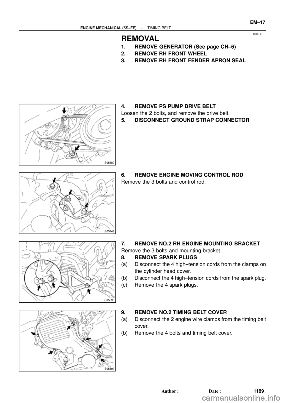
REMOVAL
1. REMOVE GENERATOR (See page CH±6)
2. REMOVE RH FRONT WHEEL
3. REMOVE RH FRONT FENDER APRON SEAL
4. REMOVE PS PUMP DRIVE BELT
Loosen the 2 bolts, and remove the drive belt.
5. DISCONNECT GROUND STRAP CONNECTOR
6. REMOVE ENGINE MOVING CONTROL ROD
Remove the 3 bolts and control rod.
7. REMOVE NO.2 RH ENGINE MOUNTING BRACKET
Remove the 3 bolts and mounting bracket.
8. REMOVE SPARK PLUGS
(a) Disconnect the 4 high±tension cords from the clamps on
the cylinder head cover.
(b) Disconnect the 4 high±tension cords from the spark plug.
(c) Remove the 4 spark plugs.
9. REMOVE NO.2 TIMING BELT COVER
(a) Disconnect the 2 engine wire clamps from the timing belt
cover.
(b) Remove the 4 bolts and timing belt cover.
Page 3410 of 4770
TIMING BELT
1190 Author�: Date�:
10. SET NO.1 CYLINDER TO TDC/COMPRESSION
(a) Turn the crankshaft pulley, an")
S05587
Turn
S05580
A02585
S05583
Pry
Move
S05593
SSTSST EM±18
± ENGINE MECHANICAL (5S±FE)TIMING BELT
1190 Author�: Date�:
10. SET NO.1 CYLINDER TO TDC/COMPRESSION
(a) Turn the crankshaft pulley, and align its groove with timing
mark º0º of the No.1 timing belt cover.
(b) Check that the hole of the camshaft timing pulley is
aligned with the timing mark of the bearing cap.
If not, turn the crankshaft 1 revolution (360°).
11. REMOVE TIMING BELT FROM CAMSHAFT TIMING
PULLEY
HINT:
When re±using timing belt:
Affix the matching marks on the timing belt and the camshaft
timing pulley, and the timing belt and the No. 1 timing belt cover.
(a) Loosen the mounting bolt of the No.1 idler pulley, and shift
the pulley toward the left as far as it will go, and temporari-
ly tighten it.
(b) Remove the timing belt from the camshaft timing pulley.
12. REMOVE CAMSHAFT TIMING PULLEY
(a) Using SST, loosen the pulley bolt.
SST 09249±63010, 09960±10010 (09962±01000,
09963±01000)
(b) Remove the bolt and timing pulley.


52 (530, 38)6")