Page 440 of 4770

CIRCUIT DESCRIPTION
The EGR system recirculates exhaust gas, which is controlled to the proper quantity to suit the
driving conditions, into the intake air mixture to slow down combustion, reduce the combustion
temperature and reduces NOx emissions. The amount of EGR is regulated by the EGR vacuum
modulator according to the engine load.
If even one of the following conditions is fulfilled,
the VSV is turned ON by a signal from the ECM.
This results in atmospheric air acting on the EGR
valve, closing the EGR valve and shutting off the
exhaust gas (EGR cut±OFF).
Under the following conditions, EGR is cut to
maintain driveability.
wEngine coolant temp. below 60�C (140�F).
wDuring deceleration (throttle valve closed).
wLight engine load (amount of intake air very
small).
wEngine speed over 4,400 rpm.
wEngine racing.
EG R gas temp. is 70�C (158�F) or below for 50
sec. under conditions (a) and (b).
(2 trip detection logic) *
(a) Engine coolant temp.: 80�C (176�F) or more.
(b) EGR operation possible (EX. A/T in 3rd speed
(5th for M/T), 55 ± 60 mph (88 ± 96 km/h),
Flat road).wOpen in EGR gas temp. sensor circuit.
wShort in VSV circuit for EGR.
wEGR hose disconnected, valve stuck.
wClogged EGR gas passage.
wECM Diagnostic Trouble Code Detecting Condition
*: See page
EG1±307.Trouble Area DTC No.
DTC 71 EGR System Malfunction
± 5S±FE ENGINECIRCUIT INSPECTIONEG1±390
Page 448 of 4770

Setting the test mode.
(1) Turn ignition switch OFF.
(2) Connect terminals TE2 and E1 of DLC2.
(3) Turn ignition switch ON.
(For checking terminal IDL, disconnect the
vacuum hose from the throttle body, then
apply vacuum to the throttle opener (See page
EG1±204).)
(For checking terminal A/C, start the engine.)
(4) Connect terminals TE1 and E1 of DLC2.
*: Before the STA signal is input (ST is not ON),
diagnostic trouble code 43 is also output. Check output condition of diagnostic trouble code 51.
Proceed to next circuit inspection shown on
matrix chart (See page EG1±327).IDL .... Go to step
A/C ... Go to step
INSPECTION PROCEDURE
PN P ... Go to page
EG1±400. Park/Neutral Position
Switch (PNP)
Accelerator pedal
depressed Accelerator pedal
released
Throttle Position
Sensor ( IDL)R, D, 2 or L position
A/C Switch (A/C)P or N position
A/C SW OFFA/C SW ONCondition
Normal*
Normal*
NormalCode
51*
51*
Check if code ª51º is output by the malfunc-
tion indicator lamp.
Diagnostic trouble code 42 is output with vehicle
speed 3 mph (5 km/h) or below.
± 5S±FE ENGINECIRCUIT INSPECTIONEG1±398
Page 449 of 4770

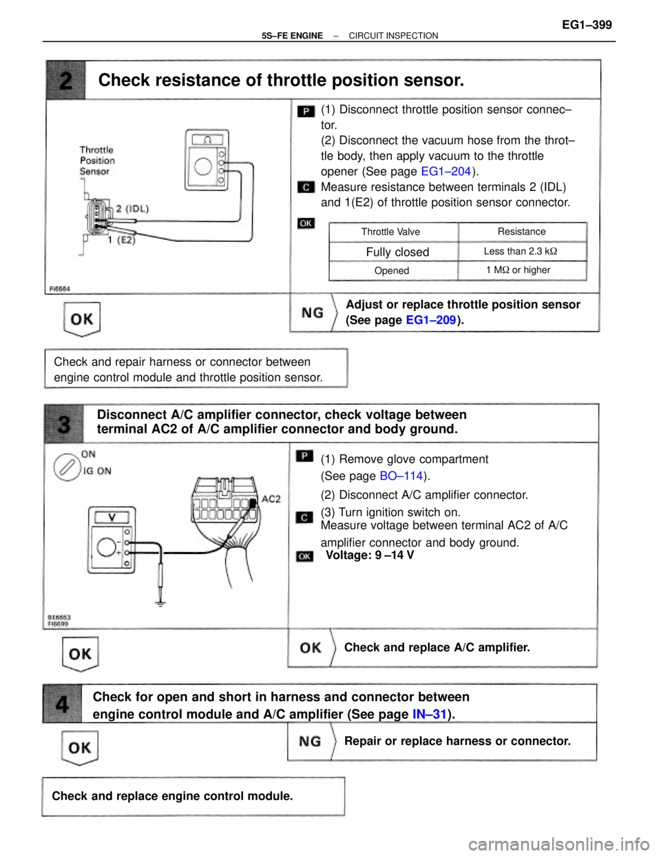
(1) Remove glove compartment
(See page BO±114).
(2) Disconnect A/C amplifier connector.
(3) Turn ignition switch on.
Measure voltage between terminal AC2 of A/C
amplifier connector and body ground.(1) Disconnect throttle position sensor connec±
tor.
(2) Disconnect the vacuum hose from the throt±
tle body, then apply vacuum to the throttle
opener (See page EG1±204).
Measure resistance between terminals 2 (IDL)
and 1(E2) of throttle position sensor connector.
Check for open and short in harness and connector between
engine control module and A/C amplifier (See page IN±31). Disconnect A/C amplifier connector, check voltage between
terminal AC2 of A/C amplifier connector and body ground.
Check and repair harness or connector between
engine control module and throttle position sensor.Adjust or replace throttle position sensor
(See page EG1±209).
Check resistance of throttle position sensor.
Check and replace engine control module.Repair or replace harness or connector. Check and replace A/C amplifier.
1 M� or higher Less than 2.3 k� Throttle Valve
Fully closed
Resistance
Opened
Voltage: 9 ±14 V
± 5S±FE ENGINECIRCUIT INSPECTIONEG1±399
Page 614 of 4770

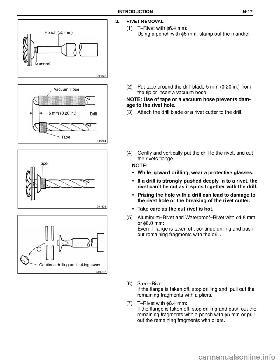
D01797
Continue drilling until taking away
D01825
Tape
D01824TapeDrill 5 mm (0.20 in.)Vacuum Hose
D01823
MandrelPonch (f5 mm)
2. RIVET REMOVAL
(1) T±Rivet with f6.4 mm:
Using a ponch with f5 mm, stamp out the mandrel.
(2) Put tape around the drill blade 5 mm (0.20 in.) from
the tip or insert a vacuum hose.
NOTE: Use of tape or a vacuum hose prevents dam-
age to the rivet hole.
(3) Attach the drill blade or a rivet cutter to the drill.
(4) Gently and vertically put the drill to the rivet, and cut
the rivets flange.
NOTE:
�While upward drilling, wear a protective glasses.
�If a drill is strongly pushed deeply in to a rivet, the
rivet can't be cut as it spins together with the drill.
�Prizing the hole with a drill can lead to damage to
the rivet hole or the breaking of the rivet cutter.
�Take care as the cut rivet is hot.
(5) Aluminum±Rivet and Waterproof±Rivet with f4.8 mm
or f6.0 mm:
Even if flange is taken off, continue drilling and push
out remaining fragments with the drill.
(6) Steel±Rivet:
If the flange is taken off, stop drilling and, pull out the
remaining fragments with a pliers.
(7) T±Rivet with f6.4 mm:
If the flange is taken off, stop drilling and push out the
remaining fragments with a ponch with f5 mm or pull
out the remaining fragments with pliers.
INTRODUCTIONIN-17
Page 1222 of 4770

E5 ENGINE COOLANT TEMP. SENSOR
1±2 : Approx. 15.04 kW (±20�C, ±4�F)
Approx. 5.74 kW (0�C, 32�F)
Approx. 2.45 kW (20�C, 68�F)
Approx. 1.15 kW (40�C, 104�F)
Approx. 0.584 kW (60�C, 140�F)
Approx. 0.318 kW (80�C, 176�F)
E7 (A), E8 (B), E9 (C), E10 (D), E11 (E)
ENGINE CONTROL MODULE
Voltage at engine control module wiring connector
BATT±E1 : Always 9.0±14.0 volts
+B±E1 :9.0±14.0 volts (Ignition SW at ON position)
VC±E2 : Always 4.5±5.5 volts (Ignition SW at ON position)
VTA1±E2 :0.3±0.8 volts (Ignition SW on and throttle valve fully closed)
:3.2±4.9 volts (Ignition SW on and throttle valve fully open)
VG±E2G :1.1±1.5 volts (Engine idling and A/C SW OFF position)
THA±E2 :0.5±3.4 volts (Engine idling and intake air temp. 20°C, 68°F)
THW±E2 :0.2±1.0 volts (Engine idling and engine coolant temp. 80°C, 176°F)
IGF±E1 :4.5±5.5 volts (Ignition SW at ON position)
Pulse generation (Engine idling)
G22+±NE± : Pulse generation (Engine idling)
NE+±NE± : Pulse generation (Engine idling)
NSW±E1 :9.0±14.0 volts (Ignition SW on and other shift position in P or N position)
Below 3.0 volts (Ignition SW on and shift position in P or N position)
SPD±E1 : Pulse generation (Ignition SW on and rotate driving wheel slowly)
TC±E1 :9.0±14.0 volts (Ignition SW at ON Position)
W±E1 : Below 3.0 volts
A/C±E1 : Below 2.0 volts (Engine idling and A/C SW on)
9.0±14.0 volts (A/C SW off)
ACT±E1 :9.0±14.0 volts (Engine idling and A/C SW on)
Below 2.0 volts (A/C SW off)
ACIS±E01 :9.0±14.0 volts (Ignition SW at ON position)
STA±E1 :6.0 volts or more (Engine cranking)
THG±E2 :4.5±5.5 volts (Ignition SW at ON position)
ELS±E1 :7.5±14.0 volts (Taillight SW at ON position)
0±1.5 volts (Taillight SW at OFF position)
ELS2±E1 :7.5±14.0 volts (Defogger SW at ON position)
0±1.5 volts (Defogger SW at OFF position)
EGR±E01 :9.0±14.0 volts (Ignition SW at ON position)
FC±E1 :9.0±14.0 volts (Ignition SW at ON position)
0±3.0 volts (Engine idling)
EVP1±E01 :9.0±14.0 volts (Ignition SW at ON position)
CF±E1 :9.0±14.0 volts (Electric cooling fan is operating on high speed)
0±2.0 volts (Electric cooling fan is operating on low speed or off)
TACH±E1 : Pulse generation (Engine idling)
TPC±E1 :9.0±14.0 volts (Ignition SW on and disconnect the vacuum hose from the vapor pressure sensor)
PTNK±E1 :3.0±3.6 volts (Ignition SW at ON position)
1.3±2.1 volts (Ignition SW on and apply vacuum 2.0 kpa (15.0 mmHg, 0.6 in.Hg)
STP±E1 :7.5±14.0 volts (Ignition SW on and brake pedal depressed)
Below 1.5 volts (Ignition SW on and brake pedal released)
SIL±E1 : Pulse generation (During transmission)
RSC, RSO±E01 :9.0±14.0 volts (Ignition SW on and disconnect E 7 of engine control module connector)
KNKL, KNKR±E1 : Pulse generation (Engine idling)
HTS, HTL, HTR±E03 :9.0±14.0 volts (Ignition SW at ON position)
0±3.0 volts (Engine idling)
OXS, OXL, OXR±E1 : Pulse generation (Maintain engine speed at 2500 rpm for two minutes after warning up)
IGT1, IGT2, IGT3±E1 : Pulse generation (Engine idling)
#10, #20, #30, #40, #50, #60±E01 :9.0±14.0 volts (Ignition SW at ON position)
Pulse generation (Engine idling)
SERVICE HINTS
Page 1532 of 4770

AC0LJ±03
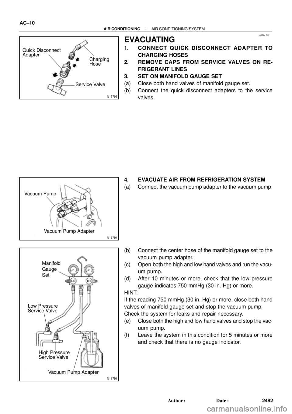
N13795
Quick Disconnect
Adapter
Charging
Service ValveHose
N13794
Vacuum Pump
Vacuum Pump Adapter
N13791
Low Pressure
Service Valve
Vacuum Pump Adapter High Pressure
Service ValveManifold
Gauge
Set
AC±10
± AIR CONDITIONINGAIR CONDITIONING SYSTEM
2492 Author�: Date�:
EVACUATING
1. CONNECT QUICK DISCONNECT ADAPTER TO
CHARGING HOSES
2. REMOVE CAPS FROM SERVICE VALVES ON RE-
FRIGERANT LINES
3. SET ON MANIFOLD GAUGE SET
(a) Close both hand valves of manifold gauge set.
(b) Connect the quick disconnect adapters to the service
valves.
4. EVACUATE AIR FROM REFRIGERATION SYSTEM
(a) Connect the vacuum pump adapter to the vacuum pump.
(b) Connect the center hose of the manifold gauge set to the
vacuum pump adapter.
(c) Open both the high and low hand valves and run the vacu-
um pump.
(d) After 10 minutes or more, check that the low pressure
gauge indicates 750 mmHg (30 in. Hg) or more.
HINT:
If the reading 750 mmHg (30 in. Hg) or more, close both hand
valves of manifold gauge set and stop the vacuum pump.
Check the system for leaks and repair necessary.
(e) Close both the high and low hand valves and stop the vac-
uum pump.
(f) Leave the system in this condition for 5 minutes or more
and check that there is no gauge indicator.
Page 2241 of 4770
BR0AM±03
F06431
± BRAKEBRAKE BOOSTER ASSEMBLY
BR±19
2042 Author�: Date�:
REMOVAL
1. REMOVE AIR CLEANER COVER WITH AIR CLEANER
HOSE
2. REMOVE MASTER CYLINDER (See page BR±11)
3. REMOVE CHARCOL CANISTER
4. DISCONNECT VACUUM HOSE FROM BRAKE
BOOSTER
5. REMOVE PEDAL RETURN SPRING
6. REMOVE CLIP AND CLEVIS PIN
7. REMOVE BRAKE BOOSTER, GASKET AND CLEVIS
(a) Remove the 4 nuts and clevis.
(b) Pull out the brake booster and gasket.
Page 2242 of 4770

BR0AN±03
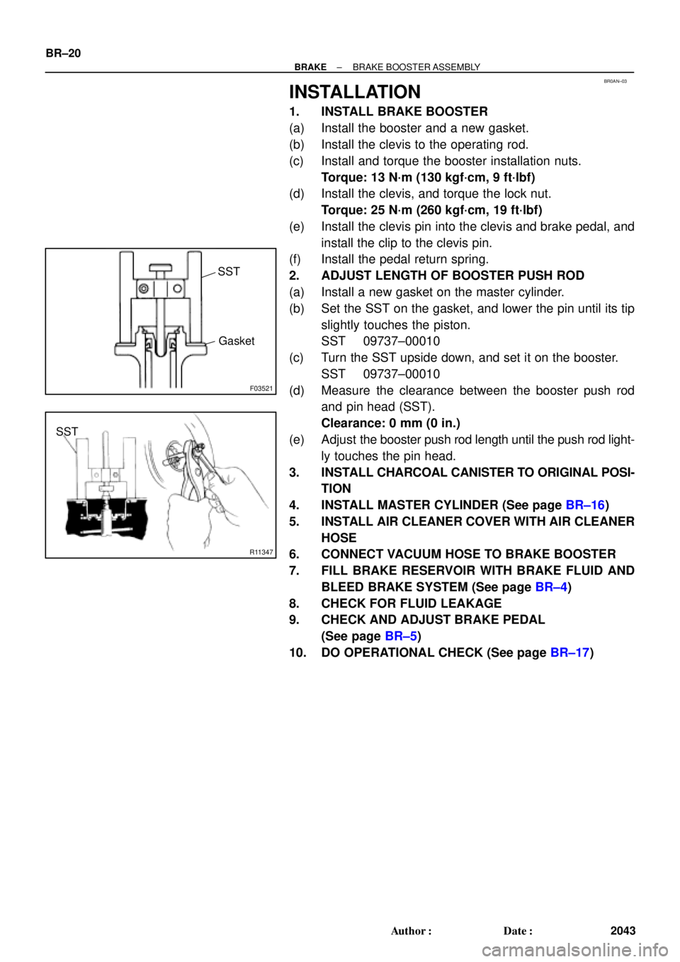
F03521
SST
Gasket
R11347
SST BR±20
± BRAKEBRAKE BOOSTER ASSEMBLY
2043 Author�: Date�:
INSTALLATION
1. INSTALL BRAKE BOOSTER
(a) Install the booster and a new gasket.
(b) Install the clevis to the operating rod.
(c) Install and torque the booster installation nuts.
Torque: 13 N´m (130 kgf´cm, 9 ft´lbf)
(d) Install the clevis, and torque the lock nut.
Torque: 25 N´m (260 kgf´cm, 19 ft´lbf)
(e) Install the clevis pin into the clevis and brake pedal, and
install the clip to the clevis pin.
(f) Install the pedal return spring.
2. ADJUST LENGTH OF BOOSTER PUSH ROD
(a) Install a new gasket on the master cylinder.
(b) Set the SST on the gasket, and lower the pin until its tip
slightly touches the piston.
SST 09737±00010
(c) Turn the SST upside down, and set it on the booster.
SST 09737±00010
(d) Measure the clearance between the booster push rod
and pin head (SST).
Clearance: 0 mm (0 in.)
(e) Adjust the booster push rod length until the push rod light-
ly touches the pin head.
3. INSTALL CHARCOAL CANISTER TO ORIGINAL POSI-
TION
4. INSTALL MASTER CYLINDER (See page BR±16)
5. INSTALL AIR CLEANER COVER WITH AIR CLEANER
HOSE
6. CONNECT VACUUM HOSE TO BRAKE BOOSTER
7. FILL BRAKE RESERVOIR WITH BRAKE FLUID AND
BLEED BRAKE SYSTEM (See page BR±4)
8. CHECK FOR FLUID LEAKAGE
9. CHECK AND ADJUST BRAKE PEDAL
(See page BR±5)
10. DO OPERATIONAL CHECK (See page BR±17)