Page 4198 of 4770
H06696
SST
H00401Weight
x y
y
R04211
Inner Diam.
Tires
(3 or More)Width
± SUPPLEMENTAL RESTRAINT SYSTEMSTEERING WHEEL PAD AND SPIRAL CABLE
RS±23
2168 Author�: Date�:
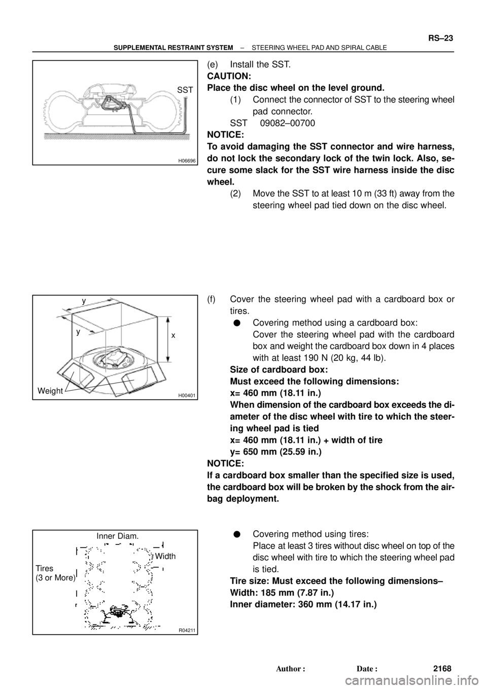
(e) Install the SST.
CAUTION:
Place the disc wheel on the level ground.
(1) Connect the connector of SST to the steering wheel
pad connector.
SST 09082±00700
NOTICE:
To avoid damaging the SST connector and wire harness,
do not lock the secondary lock of the twin lock. Also, se-
cure some slack for the SST wire harness inside the disc
wheel.
(2) Move the SST to at least 10 m (33 ft) away from the
steering wheel pad tied down on the disc wheel.
(f) Cover the steering wheel pad with a cardboard box or
tires.
�Covering method using a cardboard box:
Cover the steering wheel pad with the cardboard
box and weight the cardboard box down in 4 places
with at least 190 N (20 kg, 44 lb).
Size of cardboard box:
Must exceed the following dimensions:
x= 460 mm (18.11 in.)
When dimension of the cardboard box exceeds the di-
ameter of the disc wheel with tire to which the steer-
ing wheel pad is tied
x= 460 mm (18.11 in.) + width of tire
y= 650 mm (25.59 in.)
NOTICE:
If a cardboard box smaller than the specified size is used,
the cardboard box will be broken by the shock from the air-
bag deployment.
�Covering method using tires:
Place at least 3 tires without disc wheel on top of the
disc wheel with tire to which the steering wheel pad
is tied.
Tire size: Must exceed the following dimensions±
Width: 185 mm (7.87 in.)
Inner diameter: 360 mm (14.17 in.)
Page 4199 of 4770
R13763
10 m (33 ft) or more
AB0166
RS±24
± SUPPLEMENTAL RESTRAINT SYSTEMSTEERING WHEEL PAD AND SPIRAL CABLE
2169 Author�: Date�:
CAUTION:
Do not use tires with disc wheels.
NOTICE:
The tires may be marked by the airbag deployment, so use
the redundant tires.
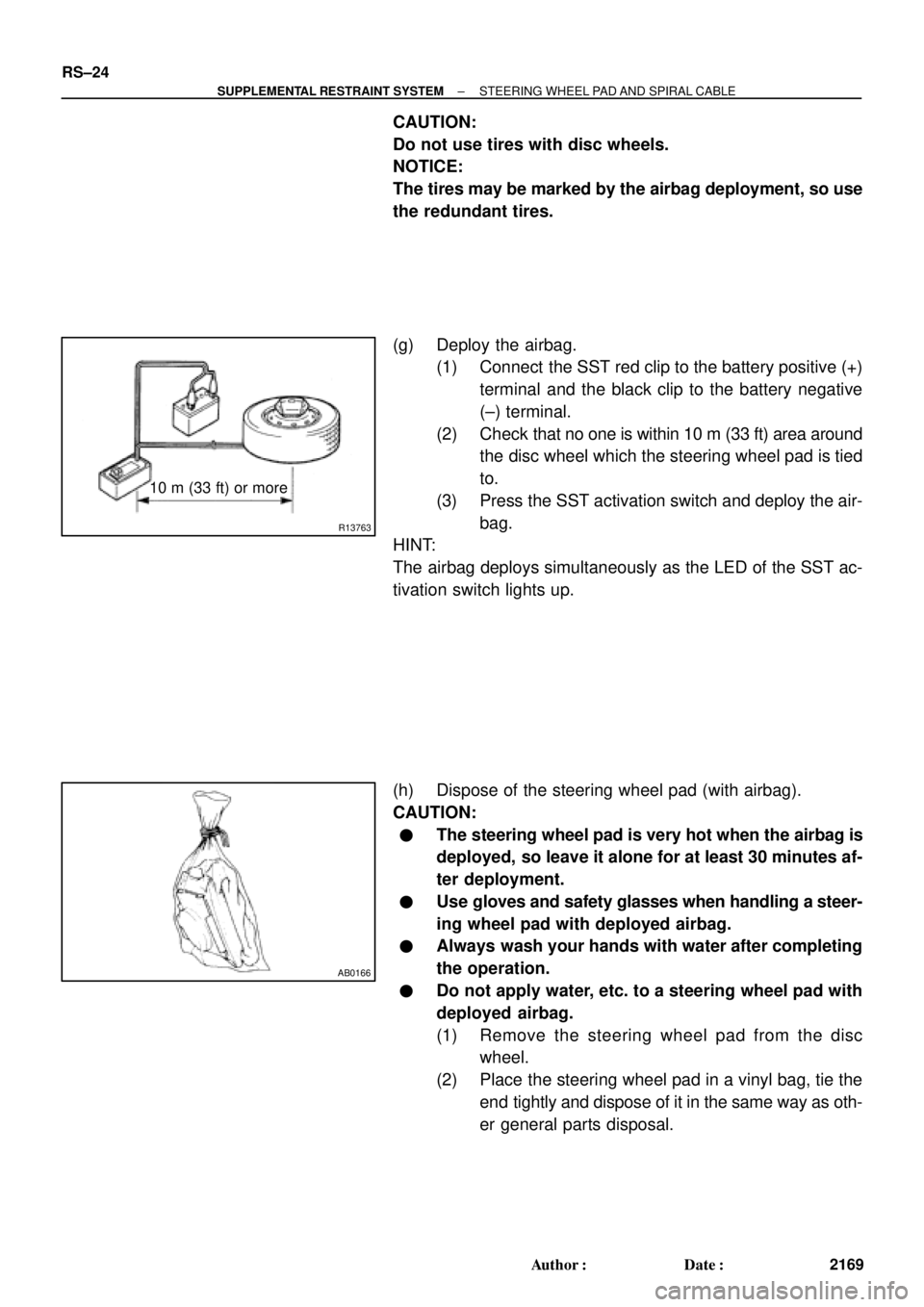
(g) Deploy the airbag.
(1) Connect the SST red clip to the battery positive (+)
terminal and the black clip to the battery negative
(±) terminal.
(2) Check that no one is within 10 m (33 ft) area around
the disc wheel which the steering wheel pad is tied
to.
(3) Press the SST activation switch and deploy the air-
bag.
HINT:
The airbag deploys simultaneously as the LED of the SST ac-
tivation switch lights up.
(h) Dispose of the steering wheel pad (with airbag).
CAUTION:
�The steering wheel pad is very hot when the airbag is
deployed, so leave it alone for at least 30 minutes af-
ter deployment.
�Use gloves and safety glasses when handling a steer-
ing wheel pad with deployed airbag.
�Always wash your hands with water after completing
the operation.
�Do not apply water, etc. to a steering wheel pad with
deployed airbag.
(1) Remove the steering wheel pad from the disc
wheel.
(2) Place the steering wheel pad in a vinyl bag, tie the
end tightly and dispose of it in the same way as oth-
er general parts disposal.
Page 4200 of 4770
RS012±19
± SUPPLEMENTAL RESTRAINT SYSTEMSTEERING WHEEL PAD AND SPIRAL CABLE
RS±25
2170 Author�: Date�:
REPLACEMENT
REPLACEMENT REQUIREMENTS
In the following cases, replace the steering wheel pad, steering wheel or spiral cable.
CaseReplacing part
If the airbag has been deployed.Steering wheel pad
If the steering wheel pad has been found to be faulty in troubleshooting.Steering wheel pad
If the spiral cable has been found to be faulty in troubleshooting.Spiral cable
If the steering wheel pad has been found to be faulty during checking items.
(See page RS±16)Steering wheel pad
If the steering wheel has been found to be faulty during checking items.
(See page RS±16)Steering wheel
If the spiral cable has been found to be faulty during checking items.
(See page RS±16)Spiral cable
If the steering wheel pad has been dropped.Steering wheel pad
CAUTION:
For removal and installation of the steering wheel pad, see page SR±11 and SR±16. Be sure to follow
the correct procedure.
Page 4201 of 4770
RS013±15
RS±26
± SUPPLEMENTAL RESTRAINT SYSTEMSTEERING WHEEL PAD AND SPIRAL CABLE
2171 Author�: Date�:
INSTALLATION
HINT:
For step 1 to 4, refer to page SR±16.
1. INSTALL SPIRAL CABLE
2. INSTALL UPPER AND LOWER COLUMN COVERS
3. INSTALL STEERING WHEEL
4. INSTALL STEERING WHEEL PAD
Page 4210 of 4770
AB0158
Battery
SST
H04528
Tires
(5 or more)
R05403
R09690
Battery
SSTFront Passenger
Airbag Assembly
10 m (33 ft) or more
± SUPPLEMENTAL RESTRAINT SYSTEMFRONT PASSENGER AIRBAG ASSEMBLY
RS±35
2180 Author�: Date�:
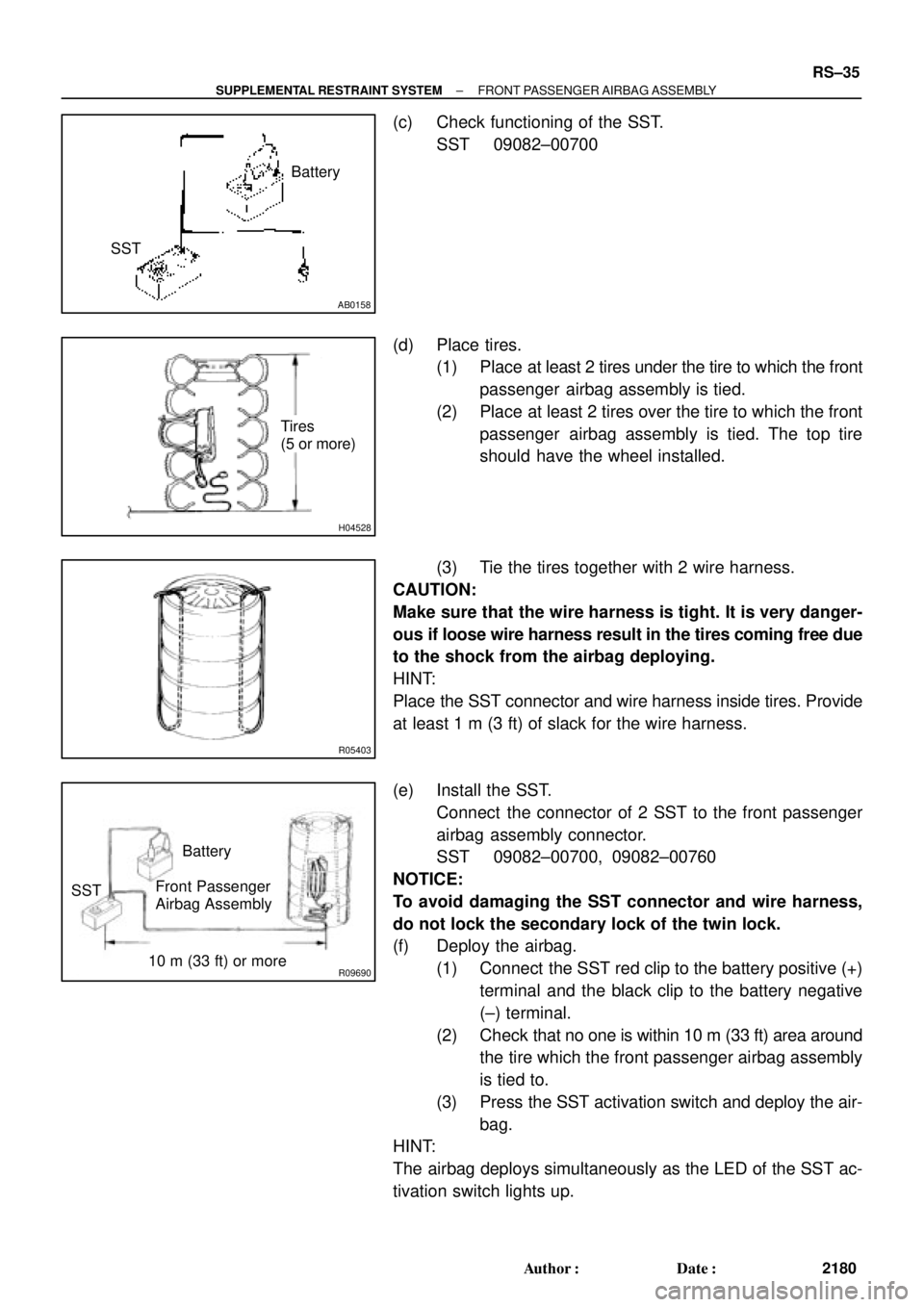
(c) Check functioning of the SST.
SST 09082±00700
(d) Place tires.
(1) Place at least 2 tires under the tire to which the front
passenger airbag assembly is tied.
(2) Place at least 2 tires over the tire to which the front
passenger airbag assembly is tied. The top tire
should have the wheel installed.
(3) Tie the tires together with 2 wire harness.
CAUTION:
Make sure that the wire harness is tight. It is very danger-
ous if loose wire harness result in the tires coming free due
to the shock from the airbag deploying.
HINT:
Place the SST connector and wire harness inside tires. Provide
at least 1 m (3 ft) of slack for the wire harness.
(e) Install the SST.
Connect the connector of 2 SST to the front passenger
airbag assembly connector.
SST 09082±00700, 09082±00760
NOTICE:
To avoid damaging the SST connector and wire harness,
do not lock the secondary lock of the twin lock.
(f) Deploy the airbag.
(1) Connect the SST red clip to the battery positive (+)
terminal and the black clip to the battery negative
(±) terminal.
(2) Check that no one is within 10 m (33 ft) area around
the tire which the front passenger airbag assembly
is tied to.
(3) Press the SST activation switch and deploy the air-
bag.
HINT:
The airbag deploys simultaneously as the LED of the SST ac-
tivation switch lights up.
Page 4221 of 4770
H01336
Tires
(5 or More)
R05403
H0133710 m (33 ft) or more SSTBattery
Side Airbag
Assembly
H00544
RS±46
± SUPPLEMENTAL RESTRAINT SYSTEMSIDE AIRBAG ASSEMBLY (TMC Made)
2191 Author�: Date�:
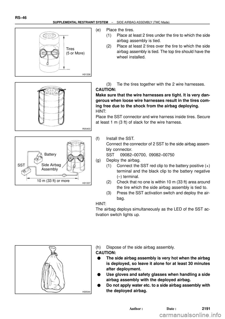
(e) Place the tires.
(1) Place at least 2 tires under the tire to which the side
airbag assembly is tied.
(2) Place at least 2 tires over the tire to which the side
airbag assembly is tied. The top tire should have the
wheel installed.
(3) Tie the tires together with the 2 wire harnesses.
CAUTION:
Make sure that the wire harnesses are tight. It is very dan-
gerous when loose wire harnesses result in the tires com-
ing free due to the shock from the airbag deploying.
HINT:
Place the SST connector and wire harness inside tires. Secure
at least 1 m (3 ft) of slack for the wire harness.
(f) Install the SST.
Connect the connector of 2 SST to the side airbag assem-
bly connector.
SST 09082±00700, 09082±00750
(g) Deploy the airbag.
(1) Connect the SST red clip to the battery positive (+)
terminal and the black clip to the battery negative
(±) terminal.
(2) Check that no one is within 10 m (33 ft) area around
the tire which the side airbag assembly is tied to.
(3) Press the SST activation switch and deploy the air-
bag.
HINT:
The airbag deploys simultaneously as the LED of the SST ac-
tivation switch lights up.
(h) Dispose of the side airbag assembly.
CAUTION:
�The side airbag assembly is very hot when the airbag
is deployed, so leave it alone for at least 30 minutes
after deployment.
�Use gloves and safety glasses when handling a side
airbag assembly with the deployed airbag.
�Do not apply water etc. to a side airbag assembly with
the deployed airbag.
Page 4248 of 4770
RS01V±11
H08282
Spiral CableCombination Meter
(Warning Light)Front Passenger Airbag Assembly
Side Airbag Assembly (RH)
Side Airbag Sensor
Assembly (RH)
Seat Belt Pretensioner (RH) Steering Wheel Pad
(with Airbag)
Side Airbag Sensor
Assembly (LH)
Seat Belt Pretensioner (LH)
Side Airbag Assembly (LH)
Airbag Sensor Assembly
Front Airbag Sensor (RH)
Front Airbag
Sensor (LH)
± SUPPLEMENTAL RESTRAINT SYSTEMWIRE HARNESS AND CONNECTOR
RS±73
2218 Author�: Date�:
WIRE HARNESS AND CONNECTOR
LOCATION
Page 4260 of 4770
P13481
No Continuity Ohmmeter
B01162
Lock
Free
B01163
Ohmmeter
Terminal 50Terminal C
Continuity
B01164
Ohmmeter
Terminal 50Continuity
ST±10
± STARTING (5S±FE)STARTER
1717 Author�: Date�:
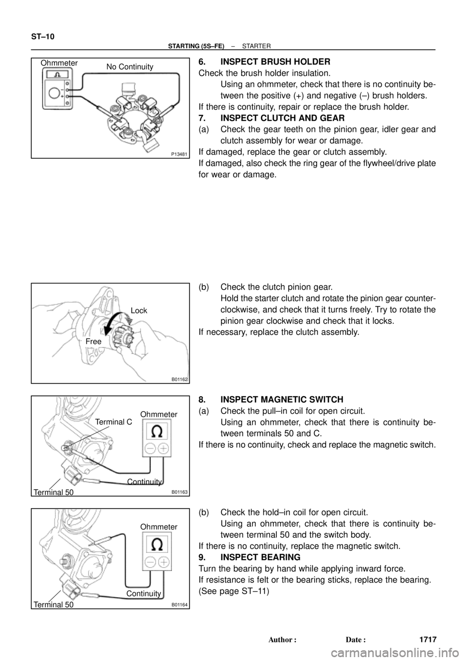
6. INSPECT BRUSH HOLDER
Check the brush holder insulation.
Using an ohmmeter, check that there is no continuity be-
tween the positive (+) and negative (±) brush holders.
If there is continuity, repair or replace the brush holder.
7. INSPECT CLUTCH AND GEAR
(a) Check the gear teeth on the pinion gear, idler gear and
clutch assembly for wear or damage.
If damaged, replace the gear or clutch assembly.
If damaged, also check the ring gear of the flywheel/drive plate
for wear or damage.
(b) Check the clutch pinion gear.
Hold the starter clutch and rotate the pinion gear counter-
clockwise, and check that it turns freely. Try to rotate the
pinion gear clockwise and check that it locks.
If necessary, replace the clutch assembly.
8. INSPECT MAGNETIC SWITCH
(a) Check the pull±in coil for open circuit.
Using an ohmmeter, check that there is continuity be-
tween terminals 50 and C.
If there is no continuity, check and replace the magnetic switch.
(b) Check the hold±in coil for open circuit.
Using an ohmmeter, check that there is continuity be-
tween terminal 50 and the switch body.
If there is no continuity, replace the magnetic switch.
9. INSPECT BEARING
Turn the bearing by hand while applying inward force.
If resistance is felt or the bearing sticks, replace the bearing.
(See page ST±11)