Page 2007 of 4770
N22592
N20984
N15432
20 mm
(0.79 in.)
BO±48
± BODYWINDSHIELD
2396 Author�: Date�:
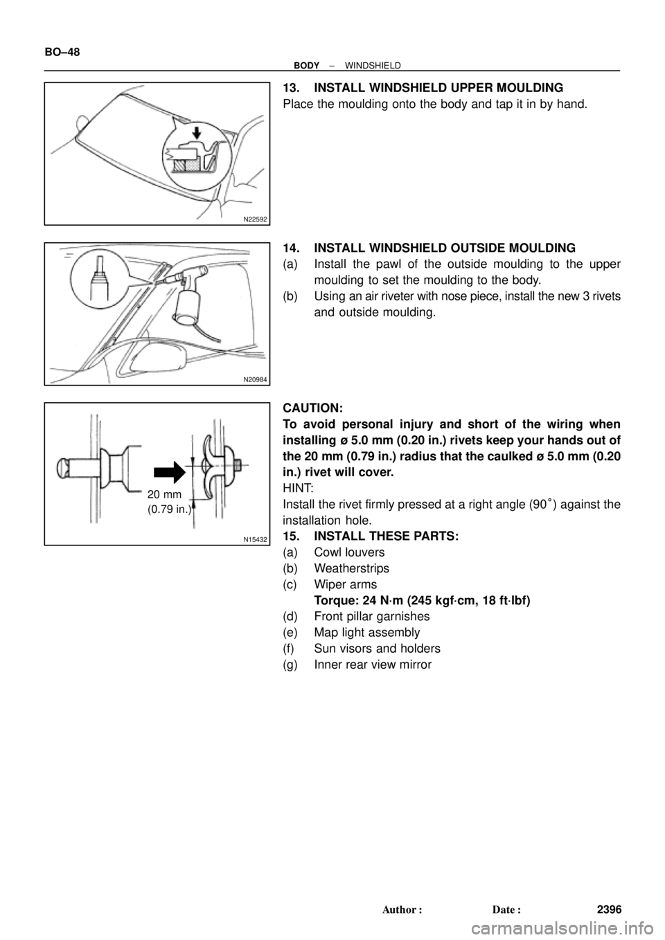
13. INSTALL WINDSHIELD UPPER MOULDING
Place the moulding onto the body and tap it in by hand.
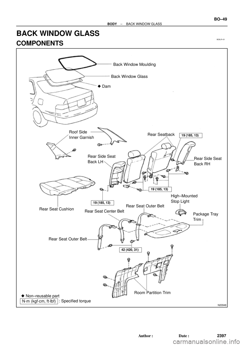
14. INSTALL WINDSHIELD OUTSIDE MOULDING
(a) Install the pawl of the outside moulding to the upper
moulding to set the moulding to the body.
(b) Using an air riveter with nose piece, install the new 3 rivets
and outside moulding.
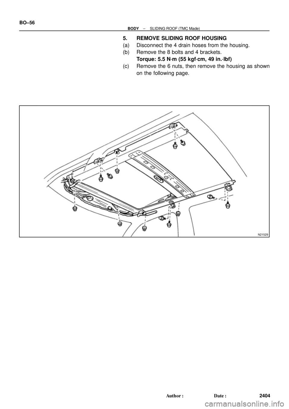
CAUTION:
To avoid personal injury and short of the wiring when
installing ù 5.0 mm (0.20 in.) rivets keep your hands out of
the 20 mm (0.79 in.) radius that the caulked ù 5.0 mm (0.20
in.) rivet will cover.
HINT:
Install the rivet firmly pressed at a right angle (90°) against the
installation hole.
15. INSTALL THESE PARTS:
(a) Cowl louvers
(b) Weatherstrips
(c) Wiper arms
Torque: 24 N´m (245 kgf´cm, 18 ft´lbf)
(d) Front pillar garnishes
(e) Map light assembly
(f) Sun visors and holders
(g) Inner rear view mirror
Page 2008 of 4770
BO0LR±01
N20948
Back Window Moulding
Back Window Glass
� Dam
Roof Side
Inner GarnishRear Seatback
19 (185, 13)
42 (420, 31)
Rear Side Seat
Back RH Rear Side Seat
Back LH
Rear Seat Cushion
19 (185, 13)
19 (185, 13)
Rear Seat Center BeltRear Seat Outer BeltHigh±Mounted
Stop Light
Package Tray
Trim
Rear Seat Outer Belt
Room Partition Trim
� Non±reusable part
N´m (kgf´cm, ft´lbf): Specified torque
± BODYBACK WINDOW GLASS
BO±49
2397 Author�: Date�:
BACK WINDOW GLASS
COMPONENTS
Page 2011 of 4770
BO±52
± BODYBACK WINDOW GLASS
2400 Author�: Date�:
(d) Room partition trims
(e) Seat belt lower side bolts
Torque: 42 N´m (420 kgf´cm, 31 ft´lbf)
(f) High±mounted stop light
(g) Roof side inner garnish
(h) Rear seatbacks and seat cushion
Torque: 18 N´m (185 kgf´cm, 13 ft´lbf)
Page 2013 of 4770
BO0M2±01
N22654
Side Garnish
Sliding Roof Glass
Rear Roof
Drip Channel
Roof Window
Deflector Panel
Side Garnish
Drive Cable
Guide Block
Guide Block
Sliding Roof
Housing
Drive Gear
Sunshade Trim
Sliding Roof
Panel Stopper Guide Rail Stopper
Roof Rail
Rear Frame
5.5 (55, 49 in.´lbf)N´m (kgf´cm, ft´lbf): Specified torque BO±54
± BODYSLIDING ROOF (TMC Made)
2402 Author�: Date�:
COMPONENTS
Page 2015 of 4770
N21529
BO±56
± BODYSLIDING ROOF (TMC Made)
2404 Author�: Date�:
5. REMOVE SLIDING ROOF HOUSING
(a) Disconnect the 4 drain hoses from the housing.
(b) Remove the 8 bolts and 4 brackets.
Torque: 5.5 N´m (55 kgf´cm, 49 in.´lbf)
(c) Remove the 6 nuts, then remove the housing as shown
on the following page.
Page 2023 of 4770
H01813
Wind deflector
Roof Drip Channel
RH Lift Arm and Cable
AssemblyDeflector Spring
Sunshade Trim RH Roof Drip Channel
Guide
LH Roof Drip Channel
Guide
Drain Cap
Drive Rail AssemblyLH Lift Arm and Cable
Assembly
5.5 (55, 49 in.´lbf)
N´m (kgf´cm, ft´lbf): Specified torque BO±64
± BODYSLIDING ROOF (TMMK Made)
2412 Author�: Date�:
Page 2024 of 4770
BO0LW±01
H01824
H01825
± BODYSLIDING ROOF (TMMK Made)
BO±65
2413 Author�: Date�:
REMOVAL
1. REMOVE ROOF HEADLINING
(See page BO±83)
2. REMOVE SIDE GARNISHES
HINT:
At the time of installation, please refer to the following item.
Soak the garnishes in water to soften them before assembly.
3. REMOVE GLASS PANEL ASSEMBLY
(a) Remove the 4 glass panel adjustment screws.
HINT:
At the time of installation, please refer to the following item.
Adjust the height of the glass panel, then tighten the 4 screws.
(b) Pull the glass upward to remove it.
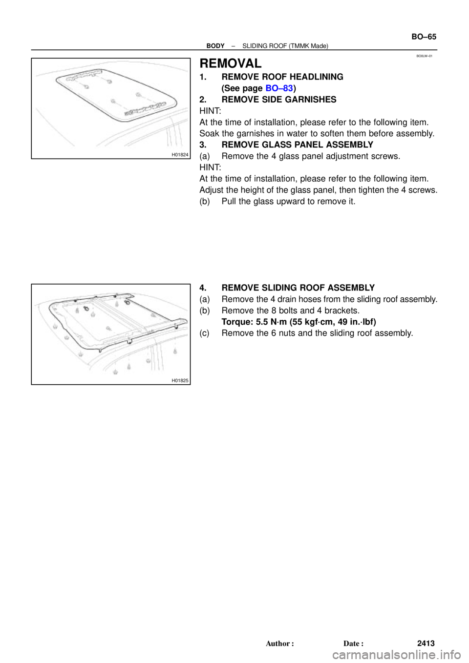
4. REMOVE SLIDING ROOF ASSEMBLY
(a) Remove the 4 drain hoses from the sliding roof assembly.
(b) Remove the 8 bolts and 4 brackets.
Torque: 5.5 N´m (55 kgf´cm, 49 in.´lbf)
(c) Remove the 6 nuts and the sliding roof assembly.
Page 2031 of 4770

BO0MB±01
N20950
Instrument Panel ReinforcementNN
DD
No.2 Instrumental Panel Bracket
No.1 Instrumental Panel Bracket
No.2 Instrumental Panel Brace
QQH N
N
N
N
GG
NG
NOB
NN
Instrument Panel Brace Mount
No.1 Instrument
Panel BraceFront Pillar Garnish
Front Pillar
GarnishFront
Passenger
Airbag
Assembly
20 (200, 14)
No.2 Side Defroster Nozzle
Cowl Side Trim
Front Door Openin
g
Cover
Instrument Panel
C
Remote Control
Mirror Hole Base
Upper Column
CoverHazard Warning
Switch
Lower Finish
PlateGlove Compartment
Door Finish PlateFront Door
Inside Scuff Plate
FFF
FJ
Glove
Compartment
No.2 Lower
Panel A
A
Cluster Finish
Panel
Lower Column
Cover
Front Door
Opening
Cover
Cowl Side
TrimD
DD
D
D
F
AA
Lower Panel
InsertCoin
BoxCombination SwitchCombination
MeterRadio Assembly
Center Cluster
Finish Panel
A/C
Control Assembly
35 (360, 26)
Steering
Wheel
Pad Steering Wheel No.1 Lower
Panel
Front Door
Inside Scuff PlateFront Console
Box
Center Console
Upper PanelF
F
B
B
Rear Console
Box
N´m (kgf´cm, ft´lbf) : Specified torque BO±72
± BODYINSTRUMENT PANEL
2420 Author�: Date�:
INSTRUMENT PANEL
COMPONENTS