Page 2079 of 4770

BO±119
2467 Author�: Date�:
REMOVAL
1. REMOVE SEAT CUSHION ASSEMBLY
(a) Remove the seat cushion assembly.
HINT:
Remove the rear seat inner with center belt from")
BO0N6±01
± BODYREAR SEAT (TMMK Made)
BO±119
2467 Author�: Date�:
REMOVAL
1. REMOVE SEAT CUSHION ASSEMBLY
(a) Remove the seat cushion assembly.
HINT:
Remove the rear seat inner with center belt from seat cushion slit to remove the seat cushion.
(b) Remove the 2 lock hooks.
2. REMOVE LH SEATBACK ASSEMBLY
(a) Release lock to lean the seatback to front.
(b) Remove the 2 bolts and LH seatback assembly.
3. w/ CRS:
REMOVE CHILD RESTRAINT SEAT
(a) Remove child restraint seat cover.
(b) Remove the 3 bolts and 2 nuts.
Torque: 13 N´m (130 kgf´cm, 9 ft´lbf)
(c) Remove the child restraint seat.
4. w/o CRS:
REMOVE RH SEATBACK ASSEMBLY
(a) Release lock to lean the seatback to front.
(b) Remove the clips.
(c) Remove the bolts and RH seatback assembly.
5. w/ CRS:
REMOVE RH SEATBACK ASSEMBLY
(a) Remove the 3 bolts.
Torque:
RH bolt: 7.8 N´m (80 kgf´cm, 69 in.´lbf)
Center bolt: 42 N´m (428 kgf´cm, 31 ft´lbf)
(b) Remove the RH seatback assembly.
6. REMOVE LH AND RH REAR SIDE SEATBACK
(a) Remove the bolt and LH rear side seatback.
(b) Remove the bolt and RH rear side seatback.
7. REMOVE SEATBACK HINGE
(a) Remove the bolt and LH seatback hinge.
(b) Remove the 2 bolts and center seatback hinge.
Torque: 18 N´m (185 kgf´cm, 13 ft´lbf)
(c) w/o CRS:
Remove the bolt and RH seatback hinge.
Torque: 18 N´m (185 kgf´cm, 13 ft´lbf)
Page 2080 of 4770
BO0N7±01
BO±120
± BODYREAR SEAT (TMMK Made)
2468 Author�: Date�:
DISASSEMBLY
1. REMOVE SEAT CUSHION COVER
Remove the hog rings and seat cushion cover from the seat cushion pad.
2. REMOVE THESE PARTS:
HINT:
Remove the clips to turn over the seatback cover before performing the following steps.
(a) Headrest
(b) Rear seatback control Bezel
(c) Headrest supports
(d) Seatback lock knob
(e) Seatback lock knob cover
(f) Rear seat center armrest
3. REMOVE SEATBACK COVER
(a) Remove the hog rings and seatback frame from the seatback cover with pad.
(b) Remove the hog rings and seatback cover from the satback pad.
4. REMOVE SEATBACK LOCK
(a) Remove the rear seatback lock control cable.
(b) Remove the 2 bolts and rear seatback lock control.
Torque: 17.5 N´m (178 kgf´cm, 12.5 ft´lbf)
Page 2083 of 4770
BO0NF±01
H01877
42 (420, 31)
Front Seat
Outer Belt
42 (420, 31)
Rear Seat
Center Belt
42 (420, 31)
Front Seat
42 (420, 31)
Front Seat Inner
Belt
42 (420, 31)
Rear Seat Inner Belt
N´m (kgf´cm, ft´lbf): Specified torque
Rear Seat
Outer Belt
7.8 (79, 69 in.´lbf)
42 (420, 31)
± BODYSEAT BELT
BO±123
2471 Author�: Date�:
SEAT BELT
COMPONENTS
Page 2094 of 4770

BO0NL±01
H01352
BO±134
± BODYSEAT BELT PRETENSIONER
2482 Author�: Date�:
INSTALLATION
NOTICE:
Never use seat belt pretensioner from another vehicle.
When replace parts, replace them with new parts.
1. INSTALL FRONT SEAT OUTER BELT
(a) Install the front seat belt parts by following the reverse or-
der of removal and torque the following bolts.
(1) Front seat outer belt retractor
Torque: 7.8 N´m (80 kgf´cm, 69 in.´lbf)
(2) Seat belt shoulder anchor
Torque: 42 N´m (430 kgf´cm, 31 ft´lbf)
(3) Seat belt floor anchor
Torque: 42 N´m (430 kgf´cm, 31 ft´lbf)
NOTICE:
�Make sure that the front seat outer belt is installed
with the specified torque.
�If the front seat outer belt has been dropped, or there
are cracks, dents or other defects in the case or con-
nector, replace the front seat outer belt with a new
one.
�When installing the front seat outer belt, take care that
the wiring does not interfere with other parts and is
not pinched between other parts.
(b) Connect the pretensioner connector as shown in the il-
lustration.
(c) w/ Seat Belt Warning:
Connect the retractor switch connector.
2. INSTALL THESE PARTS:
(a) Center pillar lower garnish
(b) Front door scuff plate
Page 2226 of 4770

F05595
F05596
BR0AB±03
F05597
R00252
BR±4
± BRAKEBRAKE FLUID
2027 Author�: Date�:
BRAKE FLUID
BLEEDING
HINT:
If any work is done on the brake system or if air is suspected in
the brake lines, bleed the air from the system.
NOTICE:
Do not let brake fluid remain on a painted surface. Wash it
off immediately.
1. FILL BRAKE RESERVOIR WITH BRAKE FLUID
Check the fluid level in the reservoir after bleeding each wheel.
Add fluid, if necessary.
Fluid: SAEJ1703 or FMVSS No.116 DOT 3
2. BLEED MASTER CYLINDER
HINT:
If the master cylinder has been disassembled or if the reservoir
becomes empty, bleed the air from the master cylinder.
(a) Disconnect the 2 brake lines from the master cylinder.
(b) Slowly depress the brake pedal and hold it.
(c) Block off the outlet plugs with your fingers, and release
the brake pedal.
(d) Repeat (b) and (c) 3 or 4 times.
3. CONNECT VINYL TUBE TO BRAKE CALIPER OR
WHEEL CYLINDER BLEEDER PLUG
Insert the other end of the tube in a half±full container of brake
fluid.
NOTICE:
Bleed air of the rear brake first. If front brake is bled first,
rear brake air cannot be bled.
4. BLEED BRAKE LINE
(a) Slowly depress the brake pedal several times.
(b) While an assistant depresses the pedal, loosen the
bleeder plug until fluid starts to run out. Then tighten the
bleeder plug.
(c) Repeat this procedure until there are no more air bubbles
in the fluid.
Torque: (Bleeder plug)
8.3 N´m (85 kgf´cm, 74 in.´lbf)
5. REPEAT PROCEDURE FOR EACH WHEEL
Page 2227 of 4770

R00954
Stop Light
Switch
Push Rod
Pedal HeightBR0YH±01
R00935
Pedal Freeplay
± BRAKEBRAKE PEDAL
BR±5
2028 Author�: Date�:
BRAKE PEDAL
ON±VEHICLE INSPECTION
1. CHECK PEDAL HEIGHT
Pedal height from asphalt sheet:
152.0 ± 162.0 mm (5.984 ± 6.378 in.)
2. IF NECESSARY, ADJUST PEDAL HEIGHT
(a) Disconnect the connector from the stop light switch.
(b) Loosen the stop light switch lock nut and remove the stop
light switch.
(c) Loosen the push rod lock nut.
(d) Adjust the pedal height by turning the pedal push rod.
(e) Tighten the push rod lock nut.
Torque: 25 N´m (260 kgf´cm, 19 ft´lbf)
(f) Install the stop light switch and turn it until it lightly con-
tacts the pedal stopper.
(g) Push in the brake pedal 5±15 mm (0.20±0.59 in.), turn the
stop light switch to lock the nut in the position where the
stop light goes off.
(h) Connect the connector to the stop light switch.
(i) After installation, push in the brake pedal 5±15 mm
(0.20±0.59 in.), check that stop light lights up.
(j) Connect the connector to the stop light switch.
(k) After adjusting the pedal height, check the pedal freeplay.
3. CHECK PEDAL FREEPLAY
(a) Stop the engine and depress the brake pedal several
times until there is no more vacuum left in the booster.
(b) Push in the pedal by hand until the resistance begins to
be felt, then measure the distance.
Pedal freeplay: 1 ± 6 mm (0.04 ± 0.24 in.)
HINT:
The freeplay to the 1st resistance is due to the play between the
clevis and pin. This is magnified up to 1 ± 6 mm (0.04 ± 0.24 in.)
at the pedal.
If incorrect, check the stop light switch clearance.
If the clearance is OK, then troubleshoot the brake system.
Stop light switch clearance:
0.5 ± 2.4 mm (0.020 ± 0.094 in.)
Page 2229 of 4770
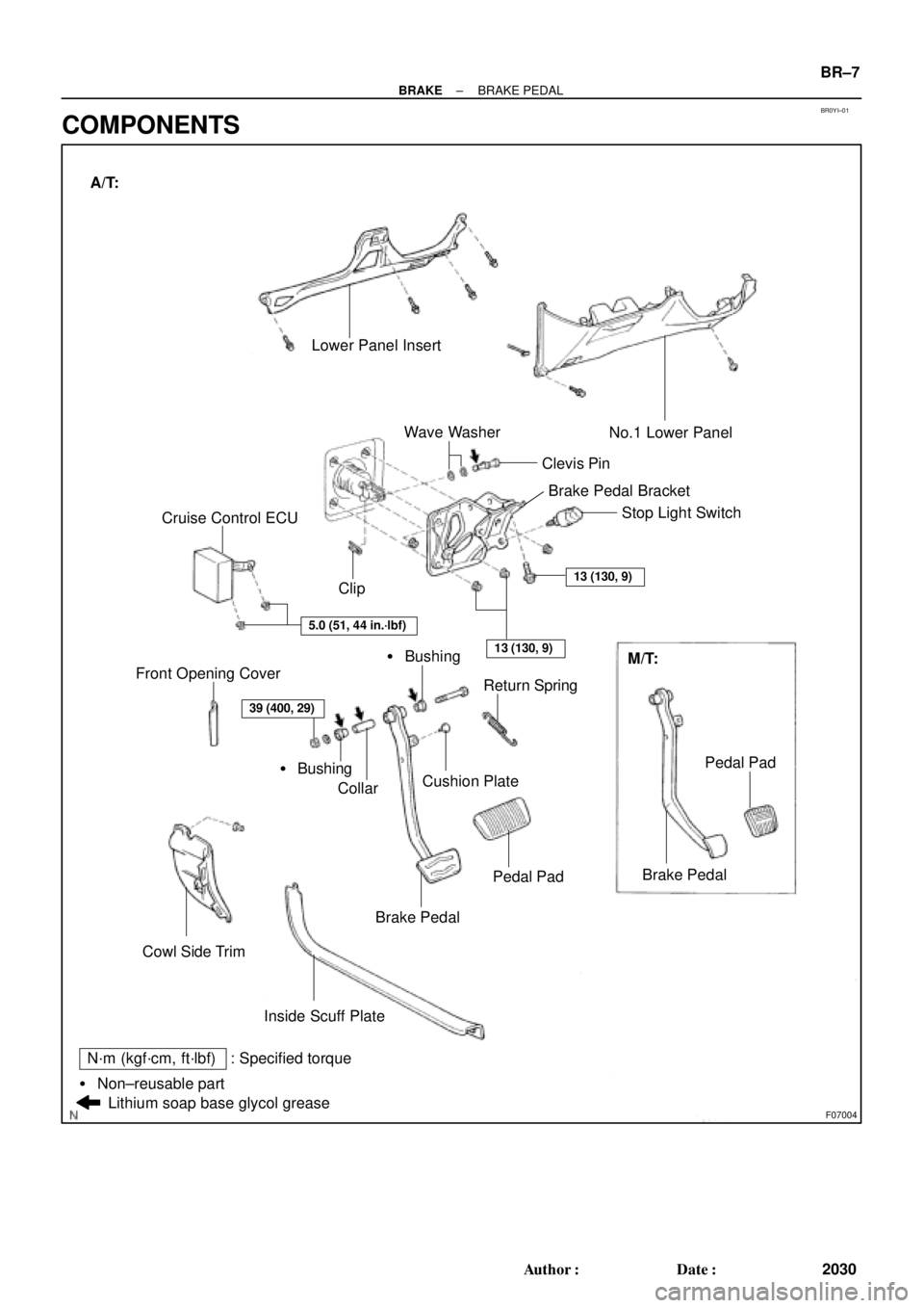
BR0YI±01
F07004
Lower Panel Insert
� Bushing ClipClevis PinNo.1 Lower Panel
Return Spring
Cushion Plate
Collar
Brake Pedal
Cowl Side Trim Front Opening Cover
Brake Pedal
Inside Scuff PlateM/T: Stop Light Switch
Wave Washer
Cruise Control ECU
Lithium soap base glycol grease
13 (130, 9)
5.0 (51, 44 in.´lbf)
13 (130, 9)
Pedal Pad
Pedal Pad� Bushing A/T:
39 (400, 29)
: Specified torqueN´m (kgf´cm, ft´lbf)
� Non±reusable partBrake Pedal Bracket
± BRAKEBRAKE PEDAL
BR±7
2030 Author�: Date�:
COMPONENTS
Page 2230 of 4770
W03254
W03255
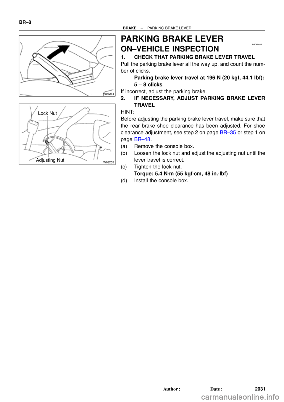
Lock Nut
Adjusting Nut
BR0AD±03
BR±8
± BRAKEPARKING BRAKE LEVER
2031 Author�: Date�:
PARKING BRAKE LEVER
ON±VEHICLE INSPECTION
1. CHECK THAT PARKING BRAKE LEVER TRAVEL
Pull the parking brake lever all the way up, and count the num-
ber of clicks.
Parking brake lever travel at 196 N (20 kgf, 44.1 lbf):
5 ± 8 clicks
If incorrect, adjust the parking brake.
2. IF NECESSARY, ADJUST PARKING BRAKE LEVER
TRAVEL
HINT:
Before adjusting the parking brake lever travel, make sure that
the rear brake shoe clearance has been adjusted. For shoe
clearance adjustment, see step 2 on page BR±35 or step 1 on
page BR±48.
(a) Remove the console box.
(b) Loosen the lock nut and adjust the adjusting nut until the
lever travel is correct.
(c) Tighten the lock nut.
Torque: 5.4 N´m (55 kgf´cm, 48 in.´lbf)
(d) Install the console box.


Front Seat
Outer Belt
42 (420, 31)
Rear Seat
Center Belt
42 (420, 31)
Front Seat
42 (420, 31)
Front Seat Inner
Belt
42 (420, 31)
Rear Seat Inner Belt
N´m (kgf´cm, ft´l")