Page 1756 of 4770
AUTOMATIC TRANSAXLECOMPONENT PARTS INSTALLATION ±
AX±123
48. CONNECT SOLENOID WIRING
(a) Connect the No.1 solenoid connector. (white and shorter
wire)
(b) Connect the No.2 solenoid connector. (black and longer
wire)
49. INSTALL 3 MAGNETS IN PLACE
NOTICE: Make sure that the magnets do not interfere with
the oil tubes.
50. INSTALL OIL PAN WITH NEW GASKET
Torque: 4.9 N´m (50 kgf´cm, 43 in.´lbf)
51. INSTALL COVER
52. INSTALL COVER BRACKET
Page 1763 of 4770

14 (0.551)36 (1.417)
AT2711
Z10940
20
(0.787)mm (in.)
45
(1.772)50
(1.969)
AT3336
± AUTOMATIC TRANSAXLE (A140E)VALVE BODY ASSEMBLY
AX±5
1898 Author�: Date�:
V")
AX038±01
Q00073
AT0103
Z10944
mm (in.)
14 (0.551)36 (1.417)
AT2711
Z10940
20
(0.787)mm (in.)
45
(1.772)50
(1.969)
AT3336
± AUTOMATIC TRANSAXLE (A140E)VALVE BODY ASSEMBLY
AX±5
1898 Author�: Date�:
VALVE BODY ASSEMBLY
ON±VEHICLE REPAIR
1. DRAIN TRANSAXLE FLUID
2. REMOVE OIL PAN AND GASKET
NOTICE:
Some fluid will remain in the oil pan.
Remove the oil pan bolts, and carefully remove the oil pan as-
sembly. Discard the gasket.
3. EXAMINE PARTICLES IN PAN
Remove the magnets and use them to collect any steel chips.
Look carefully at the chips and particles in the pan and on the
magnet to anticipate what type of wear you will find in the trans-
axle.
�Steel (magnetic): bearing, gear and plate wear
�Brass (non±magnetic): bushing wear
4. REMOVE MANUAL VALVE BODY DETENT SPRING
AND MANUAL VALVE BODY
(a) Remove the detent spring on the manual valve body.
(b) Remove the manual valve body.
5. REMOVE OIL STRAINER AND OIL PIPE BRACKET
(a) Remove the 3 bolts and the oil strainer.
(b) Remove the 2 bolts and oil pipe bracket.
NOTICE:
Be careful as oil will come out of the strainer when it is re-
moved.
Page 1764 of 4770
Z10941 AT0493
AT7868
AT0399
OR0038
Z19291
16 (0.63)
Shift Solenoid
Valve No.1
16 (0.63)Shift Solenoid
Valve No.2
AT3008
mm (in.) AX±6
± AUTOMATIC TRANSAXLE (A140E)VALVE BODY ASSEMBLY
1899 Author�: Date�:
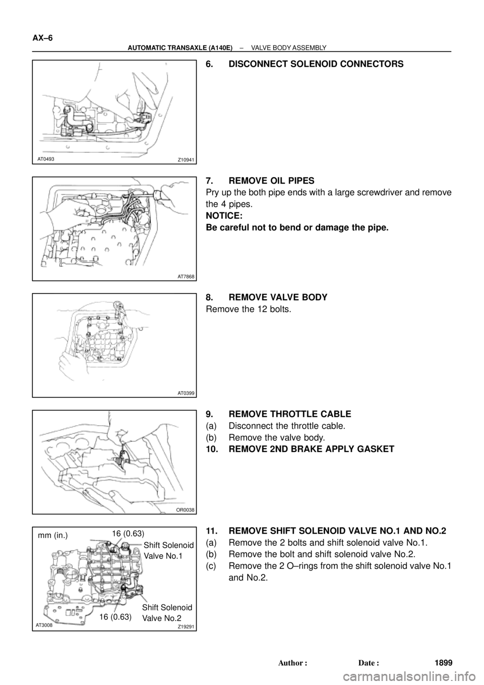
6. DISCONNECT SOLENOID CONNECTORS
7. REMOVE OIL PIPES
Pry up the both pipe ends with a large screwdriver and remove
the 4 pipes.
NOTICE:
Be careful not to bend or damage the pipe.
8. REMOVE VALVE BODY
Remove the 12 bolts.
9. REMOVE THROTTLE CABLE
(a) Disconnect the throttle cable.
(b) Remove the valve body.
10. REMOVE 2ND BRAKE APPLY GASKET
11. REMOVE SHIFT SOLENOID VALVE NO.1 AND NO.2
(a) Remove the 2 bolts and shift solenoid valve No.1.
(b) Remove the bolt and shift solenoid valve No.2.
(c) Remove the 2 O±rings from the shift solenoid valve No.1
and No.2.
Page 1765 of 4770
VALVE BODY ASSEMBLY
AX±7
1900 Author�: Date�:
12. I")
OR0038
Z10942
C
DB
A
CBA B
AT0492
AT7870
Z10941 AT0493
Shift Solenoid Valve No.2
BlackWhite
Shift Solenoid Valve No.1
± AUTOMATIC TRANSAXLE (A140E)VALVE BODY ASSEMBLY
AX±7
1900 Author�: Date�:
12. INSTALL SHIFT SOLENOID VALVE NO.1 AND NO.2
(a) Coat 2 new O±rings with ATF.
(b) Install the 2 O±rings to the shift solenoid valve No.1 and
No.2.
(c) Install the shift valve No.1 with the 2 bolts.
Torque: 5.4 N´m (55 kgf´cm, 48 in.´lbf)
(d) Install the shift valve No.2 with the bolt.
Torque: 5.4 N´m (55 kgf´cm, 48 in.´lbf)
13. INSTALL NEW 2ND BRAKE APPLY GASKET
14. INSTALL VALVE BODY
(a) While holding the cam down by your hand, slip the cable
end into the slot.
NOTICE:
Do not entangle the solenoid wire.
(b) Install the valve body with the 12 bolts.
HINT:
Temporarily install the 12 bolts first, then tighten the 12 bolts.
Torque: 10 N´m (100 kgf´cm, 7 ft´lbf)
Bolt length:
Bolt A: 20 mm (0.79 in.)
Bolt B: 25 mm (0.98 in.)
Bolt C: 36 mm (1.42 in.)
Bolt D: 50 mm (1.97 in.)
15. INSTALL OIL PIPES
Using a plastic hammer, install the 4 pipes into the positions in-
dicated in the illustration.
NOTICE:
Be careful not to bend or damage the pipes.
16. CONNECT SOLENOID CONNECTORS
Connect the black wire harness to shift solenoid valve No.2 and
white wire harness to shift solenoid valve No.1.
Page 1766 of 4770

20
(0.78)
45
(1.772)50
(1.969)
AT3336
Z10944
mm (in.)
36 (1.417)
14 (0.551)
AT2711
Z10945
Magnets
AT2368
Q00073
AX±8
± AUTOMATIC TRANSAXLE (A140E)VALVE BODY ASSEMBLY
1901 Author�: Da")
Z10940
mm (in.)
20
(0.78)
45
(1.772)50
(1.969)
AT3336
Z10944
mm (in.)
36 (1.417)
14 (0.551)
AT2711
Z10945
Magnets
AT2368
Q00073
AX±8
± AUTOMATIC TRANSAXLE (A140E)VALVE BODY ASSEMBLY
1901 Author�: Date�:
17. INSTALL OIL STRAINER AND OIL PIPE BRACKET
(a) Install the 2 bolts and oil pipe bracket.
Torque: 10 N´m (100 kgf´cm, 7 ft´lbf)
(b) Install the 3 bolts and oil strainer.
Torque: 10 N´m (100 kgf´cm, 7 ft´lbf)
18. INSTALL MANUAL VALVE BODY DETENT SPRING
AND MANUAL VALVE BODY
(a) Align the manual valve with the pin on the manual shaft
lever.
(b) Lower the manual valve body into place.
(c) Temporarily install the 4 bolts first. Then, tighten them with
a torque wrench.
Torque: 10 N´m (100 kgf´cm, 7 ft´lbf)
(d) Place the detent spring on the manual valve body and
temporarily install the 2 bolts first.
Torque: 10 N´m (100 kgf´cm, 7 ft´lbf)
(e) Check that the manual valve lever is touching the center
of the detent spring tip roller.
19. INSTALL MAGNETS IN OIL PAN
NOTICE:
Make sure that the magnets do not interfere with the oil
pipes.
20. INSTALL OIL PAN AND GASKET
Install a new gasket and oil pan with the 15 bolts.
Torque: 4.9 N´m (50 kgf´cm, 43 in.´lbf)
21. FILL FLUID AND CHECK FLUID LEVEL
(See page DI±389)
Page 1769 of 4770
Q00394
SST
AX03B±01
Q00247
SST
± AUTOMATIC TRANSAXLE (A140E)DIFFERENTIAL OIL SEAL
AX±11
1904 Author�: Date�:
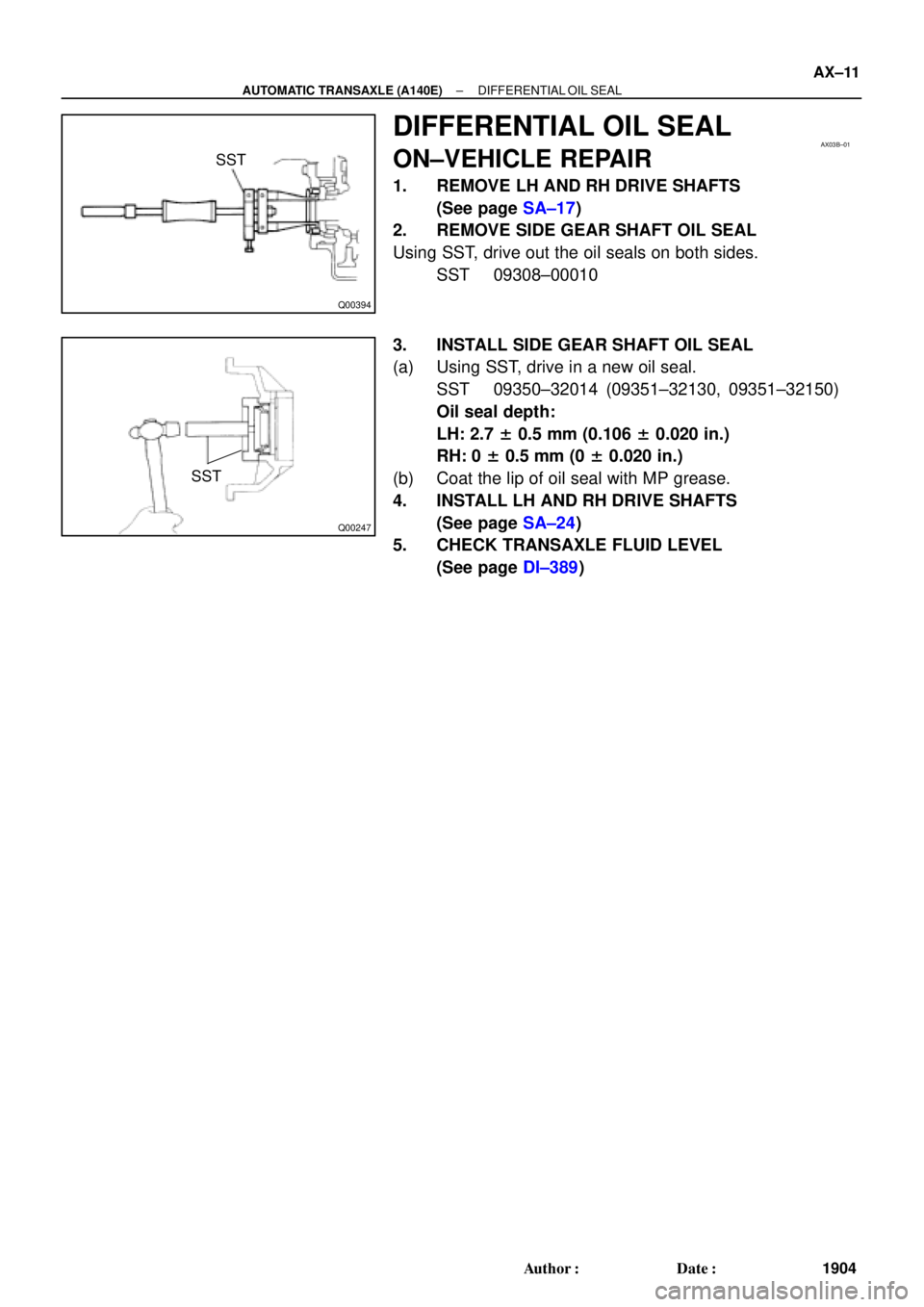
DIFFERENTIAL OIL SEAL
ON±VEHICLE REPAIR
1. REMOVE LH AND RH DRIVE SHAFTS
(See page SA±17)
2. REMOVE SIDE GEAR SHAFT OIL SEAL
Using SST, drive out the oil seals on both sides.
SST 09308±00010
3. INSTALL SIDE GEAR SHAFT OIL SEAL
(a) Using SST, drive in a new oil seal.
SST 09350±32014 (09351±32130, 09351±32150)
Oil seal depth:
LH: 2.7 ± 0.5 mm (0.106 ± 0.020 in.)
RH: 0 ± 0.5 mm (0 ± 0.020 in.)
(b) Coat the lip of oil seal with MP grease.
4. INSTALL LH AND RH DRIVE SHAFTS
(See page SA±24)
5. CHECK TRANSAXLE FLUID LEVEL
(See page DI±389)
Page 1775 of 4770
AX03G±01
Q10053
14 (145, 10)
No.1 Exhaust Pipe Support BracketClip Engine Hood
Air Cleaner Assembly
14 (145, 10)
Starter
Cruise Control Actuator
RH Drive Shaft
42 (430, 31)66 (670, 48)
39 (400, 29)
39 (400, 29)
39 (400, 29)
Hold Down Clamp
Manifold Stay
Stiffener
PlateBattery
Battery Tray � Snap Ring
�
32 (330, 24)
27 (280, 20)
Torque Converter
Clutch
x6
42 (430, 31)
42 (430, 31)
Stiffener Plate66 (670, 48)
42 (430, 31)
Exhaust
Manifold Stay66 (670, 48)
� Snap RingLH Drive Shaft
Plug for Line Pressure Test
Rear End Plate
15 (150, 11)
19 (195, 14)
25 (250, 18)
Oil Pan Insulator Shift Control Cable
N´m (kgf´cm, ft´lbf): Specified torque
� Non±reusable partTMMK
TMC
± AUTOMATIC TRANSAXLE (A140E)AUTOMATIC TRANSAXLE UNIT
AX±17
1910 Author�: Date�:
AUTOMATIC TRANSAXLE UNIT
COMPONENTS
Page 1777 of 4770
AUTOMATIC TRANSAXLE UNIT
AX±19
1912 Author�: Date�:
REMOVAL
1. REMOVE BATTERY
2. REMOVE AIR CLEANER ASSEMBLY
3. DISCONNECT THROTTLE")
AX03H±01
Q10055
Q00211
Q10056
Q10057
± AUTOMATIC TRANSAXLE (A140E)AUTOMATIC TRANSAXLE UNIT
AX±19
1912 Author�: Date�:
REMOVAL
1. REMOVE BATTERY
2. REMOVE AIR CLEANER ASSEMBLY
3. DISCONNECT THROTTLE CABLE
4. w/ CRUISE CONTROL:
REMOVE CRUISE CONTROL ACTUATOR
(a) Disconnect the connector.
(b) Remove the 3 bolts and disconnect cruise control actua-
tor with the bracket.
5. DISCONNECT OIL COOLER HOSE
6. DISCONNECT VEHICLE SPEED SENSOR CONNEC-
TOR
7. DISCONNECT PARK/NEUTRAL POSITION SWITCH
CONNECTOR
8. DISCONNECT SHIFT SOLENOID VALVE NO.1 AND
NO.2 CONNECTOR
9. DISCONNECT SHIFT SOLENOID VALVE SL CONNEC-
TOR
10. REMOVE 2 FRONT SIDE ENGINE MOUNTING BOLTS
Torque:
TMC made: 80 N´m (820 kgf´cm, 59 ft´lbf)
TMMK made:
Green color bolt: 66 N´m (670 kgf´cm, 48 ft´lbf)
Silver color bolt: 44 N´m (450 kgf´cm, 32 ft´lbf)
11. DISCONNECT 2 GROUND CABLES
12. REMOVE STARTER
(a) Disconnect the connector and remove the nut.
(b) Remove the 2 bolts, shift cable clamp and starter.
Torque: 39 N´m (400 kgf´cm, 29 ft´lbf)
13. REMOVE 3 TRANSAXLE±TO±ENGINE BOLTS
Torque: 66 N´m (670 kgf´cm, 48 ft´lbf)
 Connect the No.1 solenoid connector. (white and shorter
wire)
(b) Connect the No.2 solenoid connector. (bla")

No.1 Exhaust Pipe Support BracketClip Engine Hood
Air Cleaner Assembly
14 (145, 10)
Starter
Cruise Control Actuator
RH Drive Shaft
42 (430, 31)66 (670, 48)
39 (400, 29)
3")