Page 1531 of 4770
 Warm up engine.
(b) Inspect idle±up speed when the these conditions are es-
tablished.
�Warm up en")
± AIR CONDITIONINGAIR CONDITIONING SYSTEM
AC±9
2491 Author�: Date�:
3. INSPECT IDLE±UP SPEED
(a) Warm up engine.
(b) Inspect idle±up speed when the these conditions are es-
tablished.
�Warm up engine
�Blower speed control switch at ºHIº position
�A/C switch ON
�Temperature control dial at ºCOOLº position
Magnetic clutch conditionIdle±up speed
Magnetic clutch not engaged700 ± 50 rpm
Magnetic clutch engaged700 ± 50 rpm
If idle speed is not as specified, check ISC valve and air intake
system.
4. INSPECT FOR LEAKAGE OF REFRIGERANT
(a) Perform in these conditions:
�Stop engine.
�Secure good ventilation (If not the gas leak detector
may react to volatile gases witch are not refrigerant,
such as evaporated gasoline and exhaust gas.)
�Repeat the test 2 or 3 times.
�Make sure that there is some refrigerant remaining
in the refrigeration system.
When compressor is OFF: approx. 392 ± 588 kPa
(4 ± 6 kgf/ cm
2, 57 ± 85 psi)
(b) Bring the gas leak detector close to the drain hose before
performing the test.
HINT:
�After the blower motor stopped, leave the cooling unit for
more than 15 minutes.
�Expose the gas leak detector sensor the under the drain
hose.
�When bring the gas leak detector close to the drain hose,
make sure that the gas leak detector does not react to the
volatile gases.
If such reaction is unavoidable, the vehicle must be lifted up.
(c) If gas leak is not detected on the drain hose, remove the
blower resistor from the cooling unit. Then insert the gas
leak detector sensor into the unit and perform the test.
(d) Disconnect the connector and leave the pressure switch
for approx. 20 minutes. Then bring the gas leak detector
close to the pressure switch and perform the test.
(e) Bring the gas leak detector close to the refrigerant lines
and perform the test.
Page 1534 of 4770

N13790
Low Pressure
Service Valve
High Pressure
Service Valve
I07055
Properly
Charged
Insufficiently
Charged AC±12
± AIR CONDITIONINGAIR CONDITIONING SYSTEM
2494 Author�: Date�:
3. CHARGE REFRIGERANT INTO REFRIGERANT SYS-
TEM
If there is no leak after refrigerant leak check, charge the proper
amount of refrigerant into refrigeration system.
CAUTION:
�Never run the engine when charging the system
through the high pressure side.
�Do not open the low pressure hand valve when the
system is being charged with liquid refrigerant.
(a) Open the high pressure hand valve fully.
(b) Charge specified amount of refrigerant, then close the
high pressure hand valve.
HINT:
A fully charged system is indicated by the sight glass being free
of any bubbles.
(c) Charge partially refrigeration system with refrigerant.
(1) Set vehicle in these conditions:
�Running engine at 1,500 rpm
�Blower speed control set at ºHIº
�Temperature control set at ºMAX. COOLº
�Air inlet control set at ºRECIRCº
�Fully open doors (Sliding roof: closed)
(2) Open the low pressure hand valve.
CAUTION:
Do not open the high pressure hand valve.
(d) Charge refrigerant until bubbles disappear and check the
pressure on the gauge through the sight glass.
Page 1536 of 4770

AC21T±01
AC±14
± AIR CONDITIONINGTROUBLESHOOTING
2496 Author�: Date�:
TROUBLESHOOTING
PROBLEM SYMPTOMS TABLE
Use the table below to help you find the cause of the problem. The numbers indicate the priority of the likely
cause of the problem. Check each part in order. If necessary, replace these parts.
SymptomSuspect AreaSee page
No blower operation
4. HTR Fuse
5. Heater main relay
6. Blower motor
7. Blower resistor
8. Blower speed control switch
9. Wire harness±
AC±70
AC±63
AC±64
AC±84
±
No air temperature control1. Engine coolant volume
2. A/C control assembly±
AC±80
No air inlet control1. A/C control assemblyAC±80
No air outlet control
1. HTR Fuse
2. Air outlet servomotor
3. Mode switch±
AC±65
AC±84
No compressor operation
1. Refrigerant volume
2. A.C Fuse
3. HTR Fuse
4. Magnetic clutch relay
5. Magnetic clutch
6. Compressor
7. Pressure switch
8. Heater main relay
9. Blower speed control switch
10.A/C switch
11. *1 ECM
*
2 A/C amplifier
12.Wire harness
AC±3
±
±
AC±71
AC±39
AC±39
AC±67
AC±70
AC±84
AC±84
DI±218
AC±88
±
No compressor operates intermittently
1. Refrigerant volume
2. Condenser fan
3. Pressure switch
4. *1 ECM
*2 A/C amplifier
5. Thermistor
6. Wire harnessAC±3
AC±74
AC±67
DI±218
AC±88
AC±24
±
No cool air comes out
1. Refrigerant volume
2. Refrigerant pressure
3. Drive belt
4. Compressor lock sensor
5. Magnetic clutch
6. Compressor
7. Pressure switch
8. Thermistor
9. A/C switch
10.*1 ECM
*2 A/C amplifier
11. Wire harnessAC±3
AC±3
AC±16
AC±16
AC±39
AC±39
AC±67
AC±24
AC±84
DI±218
AC±88
±
Page 1538 of 4770
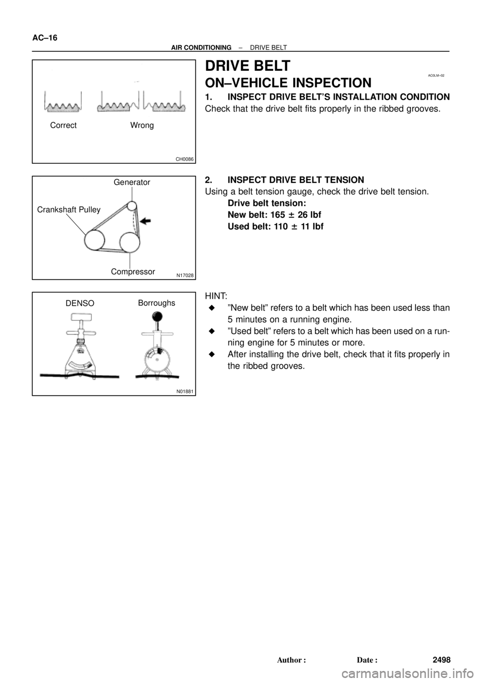
CH0086
Correct Wrong
AC0LM±02
N17028
Generator
Crankshaft Pulley
Compressor
N01881
DENSOBorroughs AC±16
± AIR CONDITIONINGDRIVE BELT
2498 Author�: Date�:
DRIVE BELT
ON±VEHICLE INSPECTION
1. INSPECT DRIVE BELT'S INSTALLATION CONDITION
Check that the drive belt fits properly in the ribbed grooves.
2. INSPECT DRIVE BELT TENSION
Using a belt tension gauge, check the drive belt tension.
Drive belt tension:
New belt: 165 ± 26 lbf
Used belt: 110 ± 11 lbf
HINT:
�ºNew beltº refers to a belt which has been used less than
5 minutes on a running engine.
�ºUsed beltº refers to a belt which has been used on a run-
ning engine for 5 minutes or more.
�After installing the drive belt, check that it fits properly in
the ribbed grooves.
Page 1561 of 4770

AC0M4±02
N01143
W
N01150
± AIR CONDITIONINGCOMPRESSOR AND MAGNETIC CLUTCH
AC±39
2521 Author�: Date�:
COMPRESSOR AND MAGNETIC
CLUTCH
ON±VEHICLE INSPECTION
1. INSPECT COMPRESSOR FOR METALLIC SOUND
(a) Start engine.
(b) Check if there is a metallic sound from the compressor
when the A/C switch is on.
If metallic sound is heard, replace the compressor assembly.
2. INSPECT REFRIGERANT PRESSURE
See ºON±VEHICLE INSPECTIONº of AIR CONDITIONING
SYSTEM on page AC±3.
3. INSPECT COMPRESSOR LOCK SENSOR RESIS-
TANCE
(a) Disconnect the connector.
(b) Measure resistance between terminals 1 and 2.
Standard resistance: 65 ± 125 W at 20 °C (68 °F)
If resistance is not as specified, replace the compressor assem-
bly.
4. INSPECT VISUALLY FOR LEAKAGE OF REFRIGER-
ANT FROM SAFETY SEAL
Using a gas leak detector, check for leakage of refrigerant.
If there is any leakage, replace the compressor assembly.
5. CHECK FOR LEAKAGE OF GREASE FROM CLUTCH
BEARING
6. CHECK FOR SIGNS OF OIL ON PRESSURE PLATE OR
ROTOR
7. INSPECT MAGNETIC CLUTCH BEARING FOR NOISE
(a) Start engine.
(b) Check for abnormal noise from near the compressor
when the A/C switch is OFF.
If abnormal noise is being emitted, replace the magnetic clutch.
8. INSPECT MAGNETIC CLUTCH OPERATION
(a) Disconnect the connector.
(b) Connect the positive (+) lead from the battery to terminal
4 and the negative (±) lead to the body ground.
(c) Check that the magnetic clutch is energized.
If operation is not as specified, replace the magnetic clutch.
Page 1570 of 4770

AC±48
± AIR CONDITIONINGCOMPRESSOR AND MAGNETIC CLUTCH
2530 Author�: Date�:
5. 1MZ±FE engine models:
CONNECT DISCHARGE HOSE
Connect the discharge hose with the bolt.
Torque: 10 N´m (100 kgf´cm, 7 ft´lbf)
NOTICE:
Hoses should be connected immediately after the caps
have been removed.
HINT:
Lubricate a new O±ring with compressor oil and install the tube.
6. INSTALL SUCTION HOSE
(a) Install the suction hose and tighten the bolt and nut.
Torque:
Piping joint: 32 N´m (330 kgf´cm, 24 ft´lbf)
Block joint: 10 N´m (100 kgf´cm, 7 ft´lbf)
HINT:
Lubricate 2 new O±rings with compressor oil and install the
hose.
(b) Install the suction hose clamping bolt.
(c) Connect the wire harness clamp.
7. INSTALL AND CHECK DRIVE BELT
(See page AC±18, AC±16)
8. CONNECT NEGATIVE (±) TERMINAL CABLE TO BAT-
TERY
9. EVACUATE AIR FROM REFRIGERATION SYSTEM
AND CHARGE SYSTEM WITH REFRIGERANT
Specified amount: 800 ± 50 g (28.22 ± 1.76 oz.)
10. INSPECT FOR LEAKAGE OF REFRIGERANT
Using a gas leak detector, check for leakage of refrigerant.
If there is leakage, check the tightening torque at the joints.
11. INSPECT A/C OPERATION
Page 1581 of 4770
AC0MM±02
± AIR CONDITIONINGEXPANSION VALVE
AC±59
2541 Author�: Date�:
EXPANSION VALVE
ON±VEHICLE INSPECTION
1. CHECK QUANTITY OF GAS DURING REFRIGERATION CYCLE
2. SET ON MANIFOLD GAUGE SET (See page AC±19)
3. RUN ENGINE
Run the engine at 1,500 rpm for at least 5 minutes.
Then check that the high pressure reading is 1.37 ± 1.57 MPa (14 ± 16 kgf/cm
2, 199 ± 228 psi).
4. CHECK EXPANSION VALVE
If the expansion valve is faulty, the low pressure reading will drop to 0 kPa (0 kgf/cm
2, 0 psi).
HINT:
When the low pressure drops to 0 kPa (0 kgf/cm
2, 0 psi), check the receiver's IN and OUT sides is no temper-
ature difference.
Page 1589 of 4770

196 kPa
(2.0 kgf/cm
2, 28 psi)High pressure side
3, 140 kPa
(32.0kgf/cm2, 455 psi)
OFF (No Continuity")
N20291
AC0N2±02
Z13470
Magnetic clutch control
Low pressure side
ON (Continuity)
196 kPa
(2.0 kgf/cm
2, 28 psi)High pressure side
3, 140 kPa
(32.0kgf/cm2, 455 psi)
OFF (No Continuity)
Z13471
1, 226 kPa
(12.5 kgf/cm2, 178 psi)OFF
(No Continuity) Condenser fan control
ON
(Continuity)150 kPa
(15.5 kgf/cm
2, 220 psi)
± AIR CONDITIONINGPRESSURE SWITCH
AC±67
2549 Author�: Date�:
PRESSURE SWITCH
ON±VEHICLE INSPECTION
1. SET ON MANIFOLD GAUGE SET
(See page AC±19)
2. DISCONNECT CONNECTOR FROM PRESSURE
SWITCH
3. RUN ENGINE AT APPROX. 1,500 RPM
4. Magnetic clutch control:
INSPECT PRESSURE SWITCH OPERATION
(a) Connect the positive (+) lead from the ohmmeter to termi-
nal 4 and negative (±) lead to terminal 1.
(b) Check continuity between terminals when refrigerant
pressure is changed, as shown in the illustration.
If operation is not as specified, replace the pressure switch.
5. Condenser fan control:
INSPECT PRESSURE SWITCH OPERATION
(a) Connect the positive (+) lead from the ohmmeter to termi-
nal 2 and negative (±) lead to terminal 3.
(b) Check continuity between terminals when refrigerant
pressure is changed, as shown in the illustration.
If operation is not as specified, replace the pressure switch.
6. STOP ENGINE AND REMOVE MANIFOLD GAUGE
SET
7. CONNECT CONNECTOR TO PRESSURE SWITCH