Page 1017 of 4770
1
GENERAL 1999 FEATURES
159EG07
VSV
(for EVAP)Service Port
Intake Air ChamberCharcoal
CanisterFuel Tank3
ENGINE
�EMISSION CONTROL SYSTEM
A service port for inspecting the evaporative emission control system has been provided between the charcoal
canister and the VSV for EVAP.
The evaporative emission control system can be inspected by connecting a pressure gauge to the service port
and performing a vacuum or a pressure test.
Refer to the repair manual for the respective model for details on the check method.
Page 1076 of 4770
![TOYOTA CAMRY 2000 Service Repair Manual NF
NEW FEATURES Ð 5S-FNE ENGINE13
�FUEL SYSTEM
1. General
�The compressed gas [maximum pressure approximately 250 kg/cm2 (3600 psi, 24.8 MPa) @215C (705F)]
from the CNG fuel tank located in the rear TOYOTA CAMRY 2000 Service Repair Manual NF
NEW FEATURES Ð 5S-FNE ENGINE13
�FUEL SYSTEM
1. General
�The compressed gas [maximum pressure approximately 250 kg/cm2 (3600 psi, 24.8 MPa) @215C (705F)]
from the CNG fuel tank located in the rear](/manual-img/14/57447/w960_57447-1075.png)
NF
NEW FEATURES Ð 5S-FNE ENGINE13
�FUEL SYSTEM
1. General
�The compressed gas [maximum pressure approximately 250 kg/cm2 (3600 psi, 24.8 MPa) @215C (705F)]
from the CNG fuel tank located in the rear section of the vehicle is routed via a fuel filter to the engine
compartment. The pressure of the fuel is then reduced to 8 kg/cm
2 (114 psi, 785 kPa).
�A pressure regulator and injectors designed exclusively for CNG application have been adopted.
�A fuel pressure sensor and a fuel temperature sensor that are used for the correction of the fuel injection
volume are located on the delivery pipe.
�The fuel tank, pressure regulator, and the delivery pipe are provided with shutoff valves that shut off
the fuel when the ignition switch is turned OFF.
In addition, these valves shut off the fuel when the engine stalls, the SRS airbag is deployed, or the
pressure in the main pipe becomes abnormally low.
�A fuel temperature sensor for the fuel gauge is mounted on the tank valve assembly, and a fuel pressure
sensor is mounted immediately upstream of the pressure regulator.
�Fuel System Diagram �
167CN12
Discharge
Valve
Fuel
Pressure
SensorFuel Temp.
SensorFuel
Pressure
RegulatorFuel Shutoff ValveFuel TankFuel Shutoff Valve
Relief Valve
Inlet Check
Valve
Fuel Temp.
Sensor
Coupler
Tank Valve Assembly
Vent Tube Manual
Shutoff
Valve Fuel
Filter
Fuel
Pressure
Sensor
Fuel Shutoff Valve Injectors
Delivery Pipe
Page 1077 of 4770
NEW FEATURES Ð 5S-FNE ENGINE 14
2. Fuel Tank
�A fuel tank made with carbon fiber and alumi-
num lining has been adopted to prevent weight
increase.
�Because the fuel tank expands along with the
increase in the pressure of the compressed gas,
the tank bands contain coil springs to accommo-
date the fluctuation in the perimeter of the tank.
�The fuel tank is provided with a tank valve as-
sembly.
3. Tank Valve Assembly
General
The tank valve assembly is mounted on the tank
and consists of a fuel shutoff valve, inlet check
valve, relief valve and two manual cutoff valves.
167CN08
Coil Springs
Tank Valve
AssemblyTank Band
167CN26
Fuel
Temperatur
Sensor
Tank Valve Assembly
Page 1078 of 4770

NF
NEW FEATURES Ð 5S-FNE ENGINE15
Fuel Shutoff Valve for Fuel Tank
This valve uses an solenoid valve. The main pipe that supplies compressed gas to the engine is connected
to this valve, which opens when the ignition switch is turned ON. If the engine stalls, this valve automatical-
ly shuts off the fuel even if the ignition switch is turned ON. The valve reopens upon restarting the engine.
Also, this valve shuts off the fuel if the SRS airbag is deployed in a collision or if the pressure in the
main pipe becomes abnormally low.
Inlet Check Valve
Connected to a filler pipe that guides the fuel that fills through the coupler, the inlet check valve shuts
off by the force of a spring and by the pressure of the gas in the tank.
During filling, the pressure of the filling gas opens the inlet check valve.
Relief Valve
A vent tube is connected to this valve.
If the fuel tank is exposed to an abnormally high temperature, this valve opens (by melting) to discharge
the CNG at a predetermined temperature, thus preventing the fuel tank from bursting due to the increase
in gas pressure.
The discharged CNG is guided under the floor through a vent tube and is released outside of the vehicle.
4. Coupler
The coupler allows the fuel to be filled when it is connected with a fuel filling nozzle. The coupler has
a built-in check valve to prevent the CNG from flowing backward.
5. Manual Shutoff Valve
This valve is mounted below the vehicle floor.
When servicing the vehicle, this valve can be manu-
ally turned 90 degrees to shut off the main pipe.
167CN09
Page 1111 of 4770
SCHEDULED MAINTENANCE LOGS19 Towing a Trailer or Using a Camper
or Car-Top Carrier
•Inspect brake linings/drums and brake pads/discs
•Inspect nuts and bolts on chassis and body
•Replace differential oil
•Replace transmission fluid or oil
•Replace transfer oil *
•Lubricate propeller shaft and re- torque bolts*
Off-Road Maintenance
If you own a Land Cruiser or a four- wheel drive RAV4,
Tacoma or 4Runner, you should check the following items
daily whenever you drive off- road through deep sand, mud
or water:
•Brake lines and hoses
•Brake linings/drums and brake pads/discs
•Engine air filter
•Differential oil
•Steering linkage
•Transfer oil
•Transmission fluid or oil
•Wheel bearings
For all four- wheel drive vehicles except RAV4, you should
also lubricate the propeller shafts daily.
Determining Your Vehicle’s Maintenance Needs
Page 1113 of 4770

SCHEDULED MAINTENANCE LOGS21 Brake Linings/Drums and Brake Pads/Discs
Check the brake linings (shoes) and drums for scoring, burning,
fluid leakage, broken parts and excessive wear. Check the pads for
excessive wear and the discs for runout, excessive wear and fluid
leakage. A qualified technician should perform these inspections.
Charcoal Canister (CA, MA and NY vehicles)
Check for internal damage and clogging. If necessary, clean
with compressed air or replace. A qualified technician should
perform these operations.
Differential Oil
Inspect each component for signs of leakage. If you discover any
leakage, have it repaired by a qualified technician immediately.
Drive Belts
Inspect for cracks, excessive wear and oiliness. Check the belt ten-
sion and adjust if necessary. Replace the belts if they are damaged.
Drive Shaft Boots
Check the drive shaft boots and clamps for cracks, deteriora-
tion and damage. Replace any damaged parts and, if necessary,
repack the grease. Selected models also require periodic inspec-
tion of the flange bolts for proper torque. A qualified technician
should perform these operations.
Engine Air Filter
Check for damage, excessive wear and oiliness. Replace if necessary.
Engine Coolant
Drain and flush the cooling system and refill with an ethylene-
glycol type coolant. A qualified technician should perform
this operation.
Engine Oil and Oil Filter
Change the oil filter and replace the engine oil with API SH,
Energy- Conserving II multigrade or ILSAC multigrade oil.
For recommended viscosity, refer to your
Owner’s Manual.
Explanation of Maintenance Items
Page 1525 of 4770

AC0LI±02
N20242
Sight Glass
± AIR CONDITIONINGAIR CONDITIONING SYSTEM
AC±3
2485 Author�: Date�:
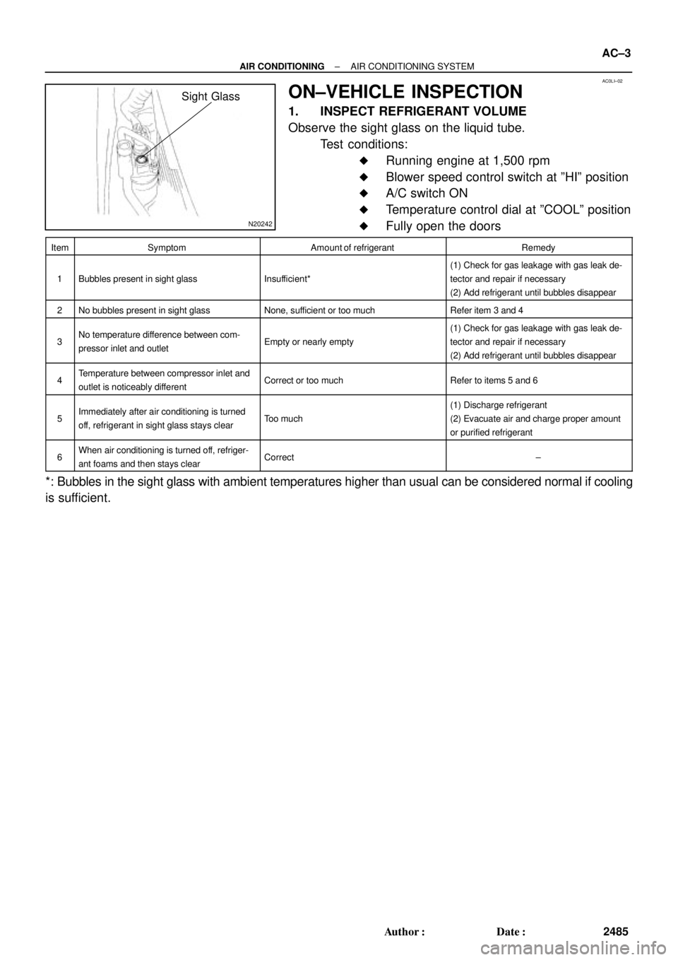
ON±VEHICLE INSPECTION
1. INSPECT REFRIGERANT VOLUME
Observe the sight glass on the liquid tube.
Test conditions:
�Running engine at 1,500 rpm
�Blower speed control switch at ºHIº position
�A/C switch ON
�Temperature control dial at ºCOOLº position
�Fully open the doors
ItemSymptomAmount of refrigerantRemedy
1Bubbles present in sight glassInsufficient*
(1) Check for gas leakage with gas leak de-
tector and repair if necessary
(2) Add refrigerant until bubbles disappear
2No bubbles present in sight glassNone, sufficient or too muchRefer item 3 and 4
3No temperature difference between com-
pressor inlet and outletEmpty or nearly empty
(1) Check for gas leakage with gas leak de-
tector and repair if necessary
(2) Add refrigerant until bubbles disappear
4Temperature between compressor inlet and
outlet is noticeably differentCorrect or too muchRefer to items 5 and 6
5Immediately after air conditioning is turned
off, refrigerant in sight glass stays clearToo much
(1) Discharge refrigerant
(2) Evacuate air and charge proper amount
or purified refrigerant
6When air conditioning is turned off, refriger-
ant foams and then stays clearCorrect±
*: Bubbles in the sight glass with ambient temperatures higher than usual can be considered normal if cooling
is sufficient.
Page 1529 of 4770

I01390
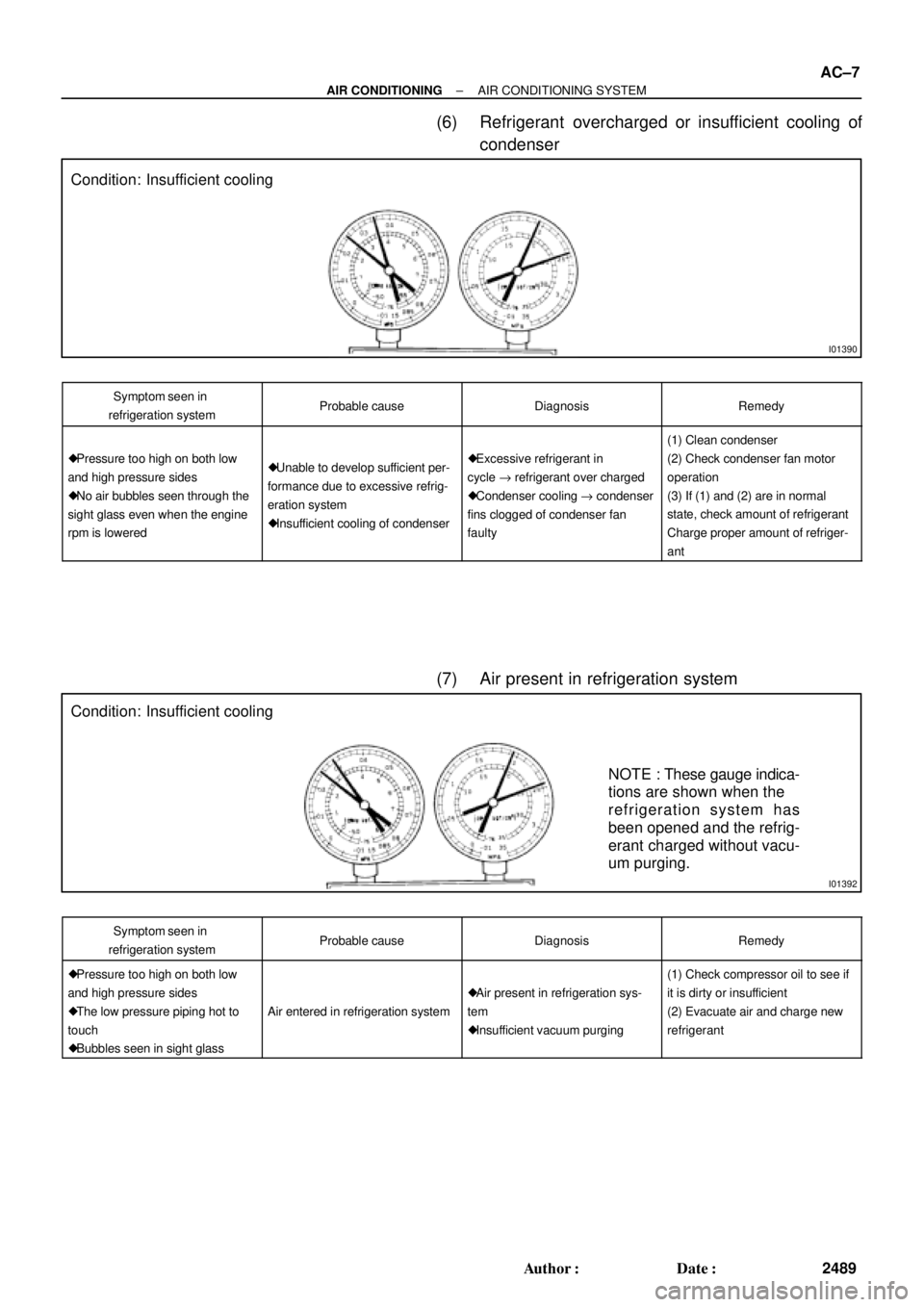
Condition: Insufficient cooling
I01392
Condition: Insufficient cooling
NOTE : These gauge indica-
tions are shown when the
refrigeration system has
been opened and the refrig-
erant charged without vacu-
um purging.
± AIR CONDITIONINGAIR CONDITIONING SYSTEM
AC±7
2489 Author�: Date�:
(6) Refrigerant overcharged or insufficient cooling of
condenser
Symptom seen in
refrigeration systemProbable causeDiagnosisRemedy
� Pressure too high on both low
and high pressure sides
� No air bubbles seen through the
sight glass even when the engine
rpm is lowered� Unable to develop sufficient per-
formance due to excessive refrig-
eration system
� Insufficient cooling of condenser� Excessive refrigerant in
cycle " refrigerant over charged
� Condenser cooling " condenser
fins clogged of condenser fan
faulty
(1) Clean condenser
(2) Check condenser fan motor
operation
(3) If (1) and (2) are in normal
state, check amount of refrigerant
Charge proper amount of refriger-
ant
(7) Air present in refrigeration system
Symptom seen in
refrigeration systemProbable causeDiagnosisRemedy
� Pressure too high on both low
and high pressure sides
� The low pressure piping hot to
touch
� Bubbles seen in sight glass
Air entered in refrigeration system
� Air present in refrigeration sys-
tem
� Insufficient vacuum purging
(1) Check compressor oil to see if
it is dirty or insufficient
(2) Evacuate air and charge new
refrigerant