Page 2222 of 4770
I03099
BE0B4±05
BE±128
± BODY ELECTRICALENGINE IMMOBILISER SYSTEM
2348 Author�: Date�:
INSPECTION
INSPECTION TRANSPONDER KEY COIL CONTINUITY
Check that continuity exists between terminal 1 and 2.
If continuity is not as specified, replace the coil.
Page 2227 of 4770

R00954
Stop Light
Switch
Push Rod
Pedal HeightBR0YH±01
R00935
Pedal Freeplay
± BRAKEBRAKE PEDAL
BR±5
2028 Author�: Date�:
BRAKE PEDAL
ON±VEHICLE INSPECTION
1. CHECK PEDAL HEIGHT
Pedal height from asphalt sheet:
152.0 ± 162.0 mm (5.984 ± 6.378 in.)
2. IF NECESSARY, ADJUST PEDAL HEIGHT
(a) Disconnect the connector from the stop light switch.
(b) Loosen the stop light switch lock nut and remove the stop
light switch.
(c) Loosen the push rod lock nut.
(d) Adjust the pedal height by turning the pedal push rod.
(e) Tighten the push rod lock nut.
Torque: 25 N´m (260 kgf´cm, 19 ft´lbf)
(f) Install the stop light switch and turn it until it lightly con-
tacts the pedal stopper.
(g) Push in the brake pedal 5±15 mm (0.20±0.59 in.), turn the
stop light switch to lock the nut in the position where the
stop light goes off.
(h) Connect the connector to the stop light switch.
(i) After installation, push in the brake pedal 5±15 mm
(0.20±0.59 in.), check that stop light lights up.
(j) Connect the connector to the stop light switch.
(k) After adjusting the pedal height, check the pedal freeplay.
3. CHECK PEDAL FREEPLAY
(a) Stop the engine and depress the brake pedal several
times until there is no more vacuum left in the booster.
(b) Push in the pedal by hand until the resistance begins to
be felt, then measure the distance.
Pedal freeplay: 1 ± 6 mm (0.04 ± 0.24 in.)
HINT:
The freeplay to the 1st resistance is due to the play between the
clevis and pin. This is magnified up to 1 ± 6 mm (0.04 ± 0.24 in.)
at the pedal.
If incorrect, check the stop light switch clearance.
If the clearance is OK, then troubleshoot the brake system.
Stop light switch clearance:
0.5 ± 2.4 mm (0.020 ± 0.094 in.)
Page 2228 of 4770
R00934
Pedal Reserve Distance BR±6
± BRAKEBRAKE PEDAL
2029 Author�: Date�:
4. CHECK PEDAL RESERVE DISTANCE
(a) Release the parking brake.
(b) With the engine running, depress the pedal and measure
the pedal reserve distance, as shown.
Pedal reserve distance from asphalt sheet at 490 N
(50 kgf, 110.2 lbf): More than 70 mm (2.76 in.)
If the reserve distance is incorrect, troubleshoot the brake sys-
tem.
Page 2239 of 4770
BR2237
BR0AK±03
BR2238
1st3rd
2nd
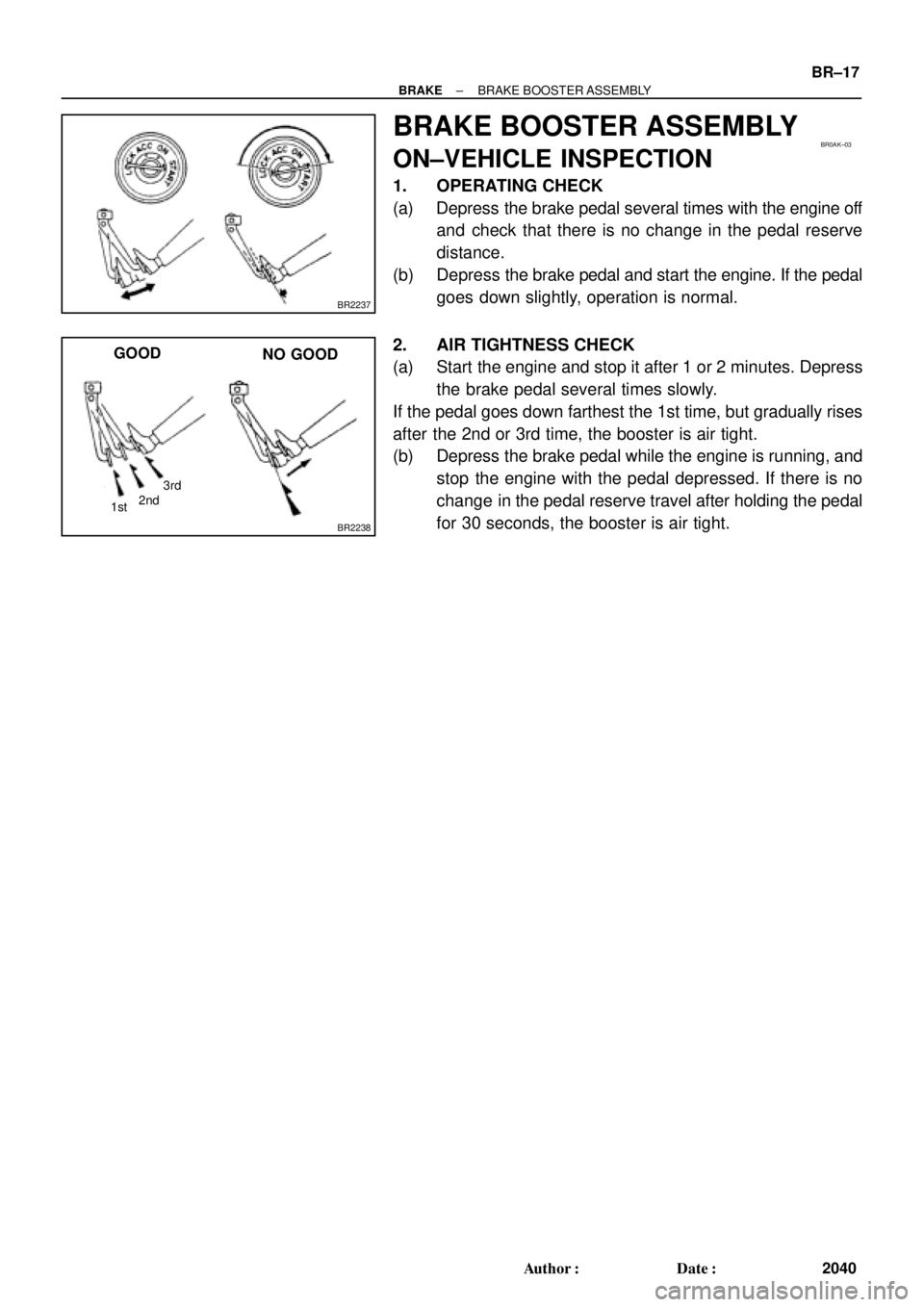
GOOD
NO GOOD
± BRAKEBRAKE BOOSTER ASSEMBLY
BR±17
2040 Author�: Date�:
BRAKE BOOSTER ASSEMBLY
ON±VEHICLE INSPECTION
1. OPERATING CHECK
(a) Depress the brake pedal several times with the engine off
and check that there is no change in the pedal reserve
distance.
(b) Depress the brake pedal and start the engine. If the pedal
goes down slightly, operation is normal.
2. AIR TIGHTNESS CHECK
(a) Start the engine and stop it after 1 or 2 minutes. Depress
the brake pedal several times slowly.
If the pedal goes down farthest the 1st time, but gradually rises
after the 2nd or 3rd time, the booster is air tight.
(b) Depress the brake pedal while the engine is running, and
stop the engine with the pedal depressed. If there is no
change in the pedal reserve travel after holding the pedal
for 30 seconds, the booster is air tight.
Page 2244 of 4770

BR0AP±03
F07213
R02874
BR±22
± BRAKEFRONT BRAKE PAD
2045 Author�: Date�:
REPLACEMENT
1. REMOVE FRONT WHEEL
Remove the wheel and temporarily fasten the disc with hub
nuts.
2. INSPECT PAD LINING THICKNESS
Check the pad thickness through the caliper inspection hole
and replace the pads if they are not within the specification.
Minimum thickness: 1.0 mm (0.039 in.)
3. LIFT UP CALIPER
(a) Remove the bolt and flexible hose from the bracket.
(b) 5S±FE engine:
Hold the sliding pin on the bottom and loosen the installa-
tion bolt, and remove the installation bolt.
(c) 1MZ±FE engine:
Remove the bottom side installation bolt.
(d) Lift up the caliper and suspend it securely.
HINT:
Do not disconnect the flexible hose from the caliper.
4. 5S±FE engine:
REMOVE 2 ANTI±SQUEAL SPRINGS
5. REMOVE 2 BRAKE PADS
6. REMOVE 4 ANTI±SQUEAL SHIMS
7. 1MZ±FE engine:
REMOVE PAD WEAR INDICATOR PLATE
8. 1MZ±FE engine:
REMOVE 2 PAD SUPPORT PLATES
9. 5S±FE engine:
REMOVE 4 PAD SUPPORT PLATES
NOTICE:
The anti±squeal springs and support plates can be used
again provided that they have sufficient rebound, no de-
formation, cracks or wear, and have had all rust, dirt and
foreign particles cleaned off.
10. CHECK DISC THICKNESS AND RUNOUT
(See page BR±28)
11. INSTALL 2 OR 4 PAD SUPPORT PLATES
12. INSTALL NEW PADS
NOTICE:
When replacing worn pads, the anti±squeal shims and
wear indicator plates must be replaced together with the
pads.
Page 2245 of 4770
 1MZ±FE engine:
Install a pad wear indicator plate on the inner pad.
(b) Apply disc brake grease to both sides of the inner anti±")
R00595
R02981
± BRAKEFRONT BRAKE PAD
BR±23
2046 Author�: Date�:
(a) 1MZ±FE engine:
Install a pad wear indicator plate on the inner pad.
(b) Apply disc brake grease to both sides of the inner anti±
squeal shims (See page BR±21).
(c) Install the 2 anti±squeal shims on each pad.
(d) Install inner pad with the pad wear indicator plate facing
upward.
(e) Install inner pad.
(f) Install outer pad.
NOTICE:
There should be no oil or grease adhering to the friction
surfaces of the pads or the disc.
(g) 5S±FE engine:
Install the 2 anti±squeal springs.
13. INSTALL CALIPER
(a) Draw out a small amount of brake fluid from the reservoir.
(b) Press in the piston with a hammer handle or similar imple-
ment.
HINT:
If the piston is difficult to push in, loosen the bleeder plug and
push in the piston while letting some brake fluid escape.
(c) Install the caliper.
(d) 5S±FE engine:
Hold the sliding pin and torque the installation bolt.
(e) 1MZ±FE engine:
Install the installation bolt.
Torque: 34 N´m (350 kgf´cm, 25 ft´lbf)
(f) Install the flexible hose and bolt to the bracket.
Torque: 29 N´m (300 kgf´cm, 21 ft´lbf)
14. INSTALL FRONT WHEEL
Torque: 103 N´m (1,050 kgf´cm, 76 ft´lbf)
15. DEPRESS BRAKE PEDAL SEVERAL TIMES
16. CHECK THAT FLUID LEVEL IS AT MAX LINE
Page 2249 of 4770

BR0AS±03
R00121
R00122
R00123
R02877
± BRAKEFRONT BRAKE CALIPER
BR±27
2050 Author�: Date�:
DISASSEMBLY
1. REMOVE SET RING AND CYLINDER BOOT
Using a screwdriver, remove the set ring and cylinder boot from
the caliper.
2. REMOVE PISTON
(a) Place a piece of cloth or similar, between the piston and
the caliper.
(b) Use compressed air to remove the piston from the cylin-
der.
CAUTION:
Do not place your fingers in front of the piston when using
compressed air.
3. REMOVE PISTON SEAL
Using a screwdriver, remove the piston seal from the cylinder.
4. REMOVE SLIDING PINS AND DUST BOOTS
(a) Remove the 2 sliding pins from the torque plate.
NOTICE:
At the time of reassembly, please refer to the following
item.
Insert the sliding pin with sliding bushing into the bottom
side (5S±FE engine) or top side (1MZ±FE engine).
(b) Using a screwdriver and hammer, tap out the 2 dust
boots.
HINT:
At the time of reassembly, please refer to the following item.
Use a 22 mm (5S±FE engine) or 24 mm (1MZ±FE engine) sock-
et wrench and tap in 2 new dust boots into the torque plate.
NOTICE:
At the time of reassembly, please refer to the following
item.
Check that the metal plate portion of the dust boot fits
snugly in the torque plate.
Page 2250 of 4770

F06988
BR0AT±03
R02878
R02879
R02880
BR±28
± BRAKEFRONT BRAKE CALIPER
2051 Author�: Date�:
INSPECTION
1. MEASURE PAD LINING THICKNESS
Using a ruler, measure the pad lining thickness.
Standard thickness:
5S±FE engine: 12.0 mm (0.472 in.)
1MZ±FE engine: 11.0 mm (0.433 in.)
Minimum thickness: 1.0 mm (0.039 in.)
Replace the pad if the pad's thickness is at the minimum thick-
ness or less, or if the pad has severe and uneven wear.
2. MEASURE DISC THICKNESS
Using a micrometer, measure the disc thickness.
Standard thickness: 28.0 mm (1.102 in.)
Minimum thickness: 26.0 mm (1.024 in.)
Replace the disc if the disc's thickness is at the minimum thick-
ness or less. Replace the disc or grind it on a lathe if it is badly
scored or worn unevenly.
3. MEASURE DISC RUNOUT
Using a dial indicator, measure disc runout 10 mm (0.39 in.)
away from the outer edge of the disc.
Maximum disc runout: 0.05 mm (0.0020 in.)
If the disc's runout is the maximum value or greater, check the
bearing play in the axial direction and check the axle hub runout
(See page SA±10). If the bearing play and axle hub runout are
not abnormal, adjust the disc runout or grind it on a ºOn±Carº
brake lathe.
4. IF NECESSARY, ADJUST DISC RUNOUT
(a) Remove the torque plate from the knuckle.
(b) Remove the hub nuts and the disc. Reinstall the disc in
the position turned 1/5 from its original position on the
hub. Install and torque the hub nuts.
Remeasure the disc runout. Make a note of the runout
and the disc's position on the hub.
Torque: 103 N´m (1,050 kgf´cm, 76 ft´lbf)
(c) Repeat (b) until the disc has been installed on the 3 re-
maining hub positions.
(d) If the minimum runout recorded in (b) and (c) is less than
0.05 mm (0.0020 in.), install the disc in that position.
(e) If the minimum runout recorded in (b) and (c) is greater
than 0.05 mm (0.0020 in.), replace the disc and repeat
step 3.
(f) Install the torque plate and torque the mounting bolts.
Torque: 107 N´m (1,090 kgf´cm, 79 ft´lbf)