Page 1596 of 4770

AC0N6±02
N20290
21
A AC±74
± AIR CONDITIONINGCONDENSER FAN
2556 Author�: Date�:
CONDENSER FAN
ON±VEHICLE INSPECTION
1. INSPECT CONDENSER FAN OPERATION
Inspect the fan operation, as shown in the chart below.
Test conditions:
�Ignition switch ON
�Blower speed control switch position ºHIº
�A/C switch ON
ConditionFan operation (Fan speed)
Engine coolant temperature
83°C (181°F) or belowNot rotate
Engine coolant temperature
98°C (208°F) or aboveRotate
Refrigerant pressure is less than
1,520 kPa (15.5 kgf/cm2, 220 psi)Not rotate (Low Speed)
Refrigerant pressure is 1,520 kPa
(15.5 kgf/cm2, 220 psi) or aboveRotate (High Speed)
If operation is not as specified, proceed next inspection.
2. INSPECT CONDENSER FAN MOTOR OPERATION
(a) Disconnect the fan connector.
(b) Connect the battery and ammeter to the connector, as
shown in the illustation.
(c) Check that the fan rotates smoothly, and then check that
the reading on the ammeter.
Specified amperage: 10.1 ± 1.8 A at 20 °C (68 °F)
�If operation is not as specified, replace the fan mo-
tor.
�If operation is as specified, check the pressure
switch, cooling fan relays and engine coolant temp.
switch.
Page 1614 of 4770
 SWITCH
2574 Author�: Date�:
ENGINE COOLANT")
AC227±01
P15233
5S±FE:
ECT Switch
P19584
1MZ±FE:No. 1 ECT Switch
No. 2 ECT Switch
P01924
P01924
AC±92
± AIR CONDITIONINGENGINE COOLANT TEMPERATURE (ECT) SWITCH
2574 Author�: Date�:
ENGINE COOLANT
TEMPERATURE (ECT) SWITCH
INSPECTION
1. DRAIN ENGINE COOLANT FROM RADIATOR
HINT:
It is not necessary to drain out all the coolant.
2. REMOVE ECT SWITCHES
(a) Disconnect the connector.
(b) Remove the ECT switch.
3. 5S±FE engine:
INSPECT ECT SWITCH CONTINUITY
(a) Using an ohmmeter, check that no continuity exists be-
tween the terminals when the coolant temperature is
above 93°C (199°F).
If continuity exists, replace the switch.
(b) Using an ohmmeter, check that continuity exists between
the terminals when the coolant temperature is below
83°C (181°F).
If no continuity exists, replace the switch.
4. 1MZ±FE engine:
INSPECT No. 1 SWITCH CONTINUITY
(a) Using an ohmmeter, check that no continuity exists be-
tween the terminals when the coolant temperature is
above 98°C (208°F).
If continuity exists, replace the switch.
(b) Using an ohmmeter, check that continuity exists between
the terminals when the coolant temperature is below
88°C (190°F).
If no continuity exists, replace the switch.
Page 1615 of 4770
P06722
P15233
5S± FE:
ECT Switch
P19584
1MZ±FE:
No. 1 ECT Switch
No. 2 ECT Switch
± AIR CONDITIONINGENGINE COOLANT TEMPERATURE (ECT) SWITCH
AC±93
2575 Author�: Date�:
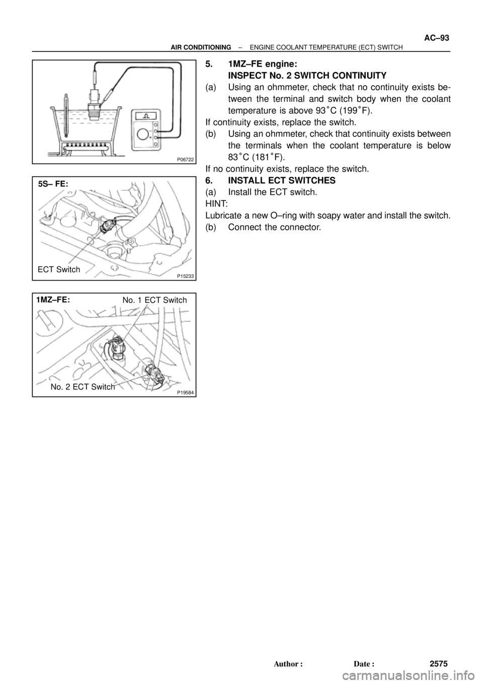
5. 1MZ±FE engine:
INSPECT No. 2 SWITCH CONTINUITY
(a) Using an ohmmeter, check that no continuity exists be-
tween the terminal and switch body when the coolant
temperature is above 93°C (199°F).
If continuity exists, replace the switch.
(b) Using an ohmmeter, check that continuity exists between
the terminals when the coolant temperature is below
83°C (181°F).
If no continuity exists, replace the switch.
6. INSTALL ECT SWITCHES
(a) Install the ECT switch.
HINT:
Lubricate a new O±ring with soapy water and install the switch.
(b) Connect the connector.
Page 1621 of 4770

INTRODUCTIONGLOSSARY OF SAE AND TOYOTA TERMS ±
IN±6
GLOSSARY OF SAE AND TOYOTA TERMS
This glossary lists all SAE±J1930 terms and abbreviations used in this manual in compliance with SAE
recommendations, as well as their Toyota equivalents.
SAE
ABBREVIATIONSSAE TERMSTOYOTA TERMS
( )±±ABBREVIATIONS
A/CAir ConditioningAir Conditioner
ACLAir CleanerAir Cleaner
AIRSecondary Air InjectionAir Injection (AI)
APAccelerator Pedal±
B+Battery Positive Voltage+B, Battery Voltage
BAROBarometric Pressure±
CACCharge Air CoolerIntercooler
CARBCarburetorCarburetor
CFIContinuous Fuel Injection±
CKPCrankshaft PositionCrank Angle
CLClosed LoopClosed Loop
CMPCamshaft PositionCam Angle
CPPClutch Pedal Position±
CTOXContinuous Trap Oxidizer±
CTPClosed Throttle Position±
DFIDirect Fuel Injection (Diesel)Direct Injection (DI)
DIDistributor Ignition±
DLC1
DLC2
DLC3Data Link Connector 1
Data Link Connector 2
Data Link Connector 31: Check Connector
2: Toyota Diagnosis Communication Link (TDCL)
3: OBD@@@@@: [g 2] Diagnostic Connector
DTCDiagnostic Trouble CodeDiagnostic Code
DTMDiagnostic Test Mode±
ECLEngine Control Level±
ECMEngine Control ModuleEngine ECU (Electronic Control Unit)
ECTEngine Coolant TemperatureCoolant Temperature, Water Temperature (THW)
EEPROMElectrically Erasable Programmable Read Only
MemoryElectrically Erasable Programmable Read Only Memory
(EEPROM),
Erasable Programmable Read Only Memory(EPROM)
EFEEarly Fuel EvaporationCold Mixture Heater (CMH), Heat Control Valve (HCV)
EGRExhaust Gas RecirculationExhaust Gas Recirculation (EGR)
EIElectronic IgnitionToyota Distributorless Ignition (TDI)
EMEngine ModificationEngine Modification (EM)
EPROMErasable Programmable Read Only MemoryProgrammable Read Only Memory (PROM)
EVAPEvaporative EmissionEvaporative Emission Control (EVAP)
FCFan Control±
FEEPROMFlash Electrically Erasable Programmable
Read Only Memory±
FEPROMFlash Erasable Programmable Read Only Memory±
FFFlexible Fuel±
FPFuel PumpFuel Pump
GENGeneratorAlternator
GNDGroundGround (GND)
HO2SHeated Oxygen SensorHeated Oxygen Sensor (HO2S)
IN016±02
Page 1622 of 4770

IATIntake Air TemperatureIntake or Inlet Air Temperature
ICMIgnition Control Module±
IFIIndirect Fuel")
INTRODUCTIONGLOSSARY OF SAE AND TOYOTA TERMS ±
IN±7
IACIdle Air ControlIdle Speed Control (ISC)
IATIntake Air TemperatureIntake or Inlet Air Temperature
ICMIgnition Control Module±
IFIIndirect Fuel InjectionIndirect Injection
IFSInertia Fuel±Shutoff±
ISCIdle Speed Control±
KSKnock SensorKnock Sensor
MAFMass Air FlowAir Flow Meter
MAPManifold Absolute PressureManifold Pressure
Intake Vacuum
MCMixture Control
Electric Bleed Air Control Valve (EBCV)
Mixture Control Valve (MCV)
Electric Air Control Valve (EACV)
MDPManifold Differential Pressure±
MFIMultiport Fuel InjectionElectronic Fuel Injection (EFI)
MILMalfunction Indicator LampCheck Engine Light
MSTManifold Surface Temperature±
MVZManifold Vacuum Zone±
NVRAMNon±Volatile Random Access Memory±
O2SOxygen SensorOxygen Sensor, O2 Sensor (O2S)
OBDOn±Board DiagnosticOn±Board Diagnostic (OBD)
OCOxidation Catalytic ConverterOxidation Catalyst Converter (OC), CCo
OPOpen LoopOpen Loop
PAIRPulsed Secondary Air InjectionAir Suction (AS)
PCMPowertrain Control Module±
PNPPark/Neutral Position±
PROMProgrammable Read Only Memory±
PSPPower Steering Pressure±
PTOXPeriodic Trap OxidizerDiesel Particulate Filter (DPF)
Diesel Particulate Trap (DPT)
RAMRandom Access MemoryRandom Access Memory (RAM)
RMRelay Module±
ROMRead Only MemoryRead Only Memory (ROM)
RPMEngine SpeedEngine Speed
SCSuperchargerSupercharger
SCBSupercharger Bypass±
SFISequential Multiport Fuel InjectionElectronic Fuel Injection (EFI), Sequential Injection
SPLSmoke Puff Limiter±
SRIService Reminder Indicator±
SRTSystem Readiness Test±
STScan Tool±
TBThrottle BodyThrottle Body
TBIThrottle Body Fuel InjectionSingle Point Injection
Central Fuel Injection (Ci)
TCTurbochargerTurbocharger
TCCTorque Converter ClutchTorque Converter
TCMTransmission Control ModuleTransmission ECU (Electronic Control Unit)
TPThrottle PositionThrottle Position
TRTransmission Range±
Page 1767 of 4770
200 mm
(7.87 in.)
± AUTOMATIC TRANSAXLE (A140E)THROTTLE CABLE
AX±9
1902 Author�: Date�:
THROTTLE CABLE
ON±VEHICLE REPAIR
1. DISCONNECT THROT")
AX039±01
Q10052
Q10339
0.8 ± 1.5 mm(0.031 ± 0.059 in.)200 mm
(7.87 in.)
± AUTOMATIC TRANSAXLE (A140E)THROTTLE CABLE
AX±9
1902 Author�: Date�:
THROTTLE CABLE
ON±VEHICLE REPAIR
1. DISCONNECT THROTTLE CABLE
(a) Disconnect the cable from the throttle linkage.
(b) Disconnect the cable from the cable clamps in the engine
compartment.
2. REMOVE PARK/NEUTRAL POSITION SWITCH
(See page AX±4)
3. REMOVE VALVE BODY (See page AX±5)
4. REMOVE THROTTLE CABLE
(a) Remove the retaining bolt and plate.
(b) Pull out the cable from the transaxle case.
5. IF THROTTLE CABLE IS NEW, STAKE STOPPER OR
PAINT MARK ON INNER CABLE
HINT:
New cable does not have a staked cable stopper.
(a) Bend the cable to ensure a radius of about 200 mm (7.87
in.).
(b) Pull the inner cable lightly until a slight resistance is felt,
and hold it there.
(c) Stake the stopper, 0.8 ± 1.5 mm (0.031 ± 0.059 in.) from
the end of the outer cable.
(d) Install a new O±ring to the throttle cable.
(e) Push in the throttle cable and install the retaining bolt.
6. INSTALL VALVE BODY (See page AX±5)
7. INSTALL PARK/NEUTRAL POSITION SWITCH
(See page AX±4)
8. CONNECT THROTTLE CABLE
9. FILL FLUID AND CHECK FLUID LEVEL
(See page DI±389)
10. ADJUST THROTTLE CABLE (See page DI±389)
Page 1783 of 4770
AX03I±01
AT3412
± AUTOMATIC TRANSAXLE (A140E)AUTOMATIC TRANSAXLE UNIT
AX±25
1918 Author�: Date�:
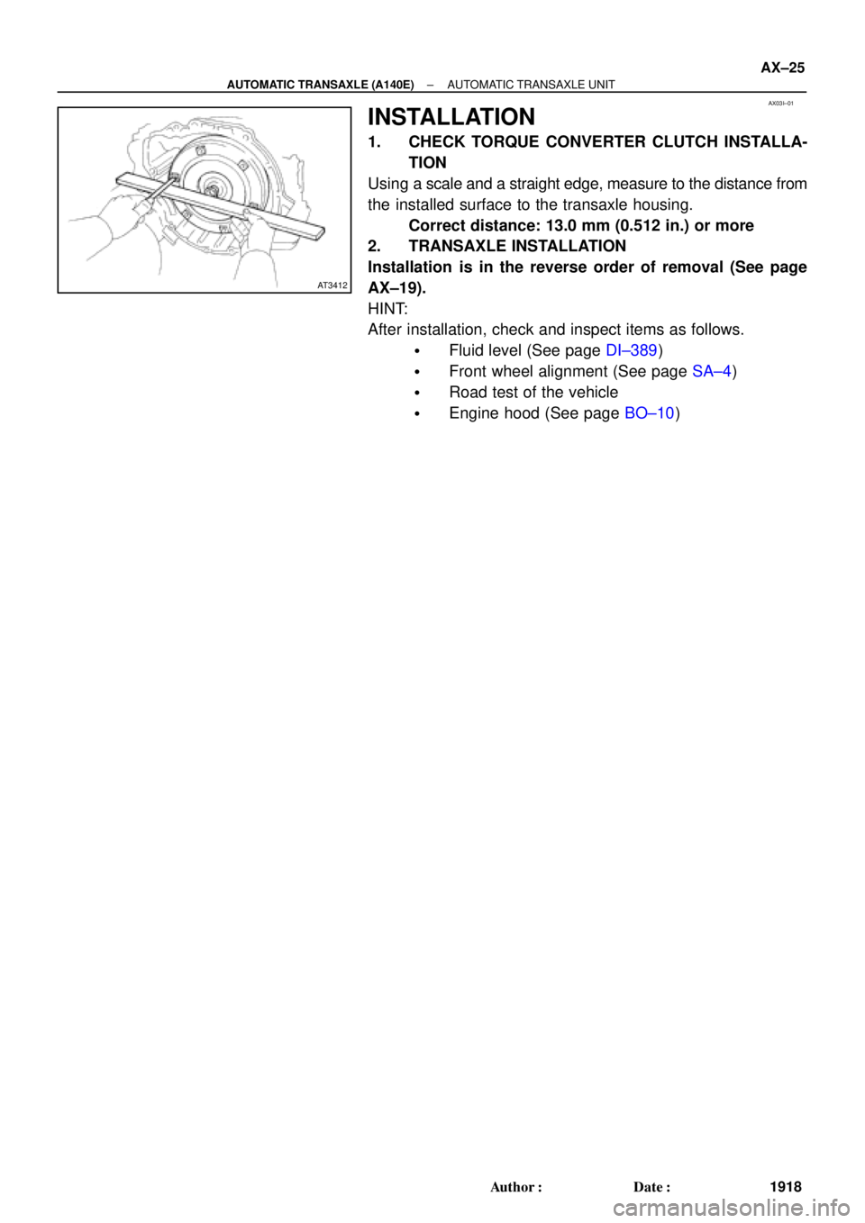
INSTALLATION
1. CHECK TORQUE CONVERTER CLUTCH INSTALLA-
TION
Using a scale and a straight edge, measure to the distance from
the installed surface to the transaxle housing.
Correct distance: 13.0 mm (0.512 in.) or more
2. TRANSAXLE INSTALLATION
Installation is in the reverse order of removal (See page
AX±19).
HINT:
After installation, check and inspect items as follows.
�Fluid level (See page DI±389)
�Front wheel alignment (See page SA±4)
�Road test of the vehicle
�Engine hood (See page BO±10)
Page 1791 of 4770

INTRODUCTIONGLOSSARY OF SAE AND TOYOTA TERMS ±
IN±6
GLOSSARY OF SAE AND TOYOTA TERMS
This glossary lists all SAE±J1930 terms and abbreviations used in this manual in compliance with SAE
recommendations, as well as their Toyota equivalents.
SAE
ABBREVIATIONSSAE TERMSTOYOTA TERMS
( )±±ABBREVIATIONS
A/CAir ConditioningAir Conditioner
ACLAir CleanerAir Cleaner
AIRSecondary Air InjectionAir Injection (AI)
APAccelerator Pedal±
B+Battery Positive Voltage+B, Battery Voltage
BAROBarometric Pressure±
CACCharge Air CoolerIntercooler
CARBCarburetorCarburetor
CFIContinuous Fuel Injection±
CKPCrankshaft PositionCrank Angle
CLClosed LoopClosed Loop
CMPCamshaft PositionCam Angle
CPPClutch Pedal Position±
CTOXContinuous Trap Oxidizer±
CTPClosed Throttle Position±
DFIDirect Fuel Injection (Diesel)Direct Injection (DI)
DIDistributor Ignition±
DLC1
DLC2
DLC3Data Link Connector 1
Data Link Connector 2
Data Link Connector 31: Check Connector
2: Toyota Diagnosis Communication Link (TDCL)
3: OBD@@@@@: [g 2] Diagnostic Connector
DTCDiagnostic Trouble CodeDiagnostic Code
DTMDiagnostic Test Mode±
ECLEngine Control Level±
ECMEngine Control ModuleEngine ECU (Electronic Control Unit)
ECTEngine Coolant TemperatureCoolant Temperature, Water Temperature (THW)
EEPROMElectrically Erasable Programmable Read Only
MemoryElectrically Erasable Programmable Read Only Memory
(EEPROM),
Erasable Programmable Read Only Memory(EPROM)
EFEEarly Fuel EvaporationCold Mixture Heater (CMH), Heat Control Valve (HCV)
EGRExhaust Gas RecirculationExhaust Gas Recirculation (EGR)
EIElectronic IgnitionToyota Distributorless Ignition (TDI)
EMEngine ModificationEngine Modification (EM)
EPROMErasable Programmable Read Only MemoryProgrammable Read Only Memory (PROM)
EVAPEvaporative EmissionEvaporative Emission Control (EVAP)
FCFan Control±
FEEPROMFlash Electrically Erasable Programmable
Read Only Memory±
FEPROMFlash Erasable Programmable Read Only Memory±
FFFlexible Fuel±
FPFuel PumpFuel Pump
GENGeneratorAlternator
GNDGroundGround (GND)
HO2SHeated Oxygen SensorHeated Oxygen Sensor (HO2S)
IN016±02