Page 3208 of 4770

H01026H06508H06509
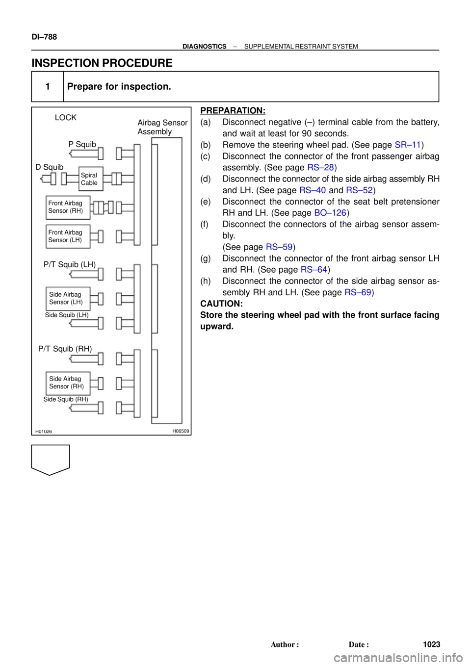
LOCK
Airbag Sensor
Assembly
P Squib
D Squib
P/T Squib (LH)
Side Squib (LH)
P/T Squib (RH)
Side Squib (RH)Spiral
Cable
Side Airbag
Sensor (LH)
Side Airbag
Sensor (RH) Front Airbag
Sensor (LH) Front Airbag
Sensor (RH)
DI±788
± DIAGNOSTICSSUPPLEMENTAL RESTRAINT SYSTEM
1023 Author�: Date�:
INSPECTION PROCEDURE
1 Prepare for inspection.
PREPARATION:
(a) Disconnect negative (±) terminal cable from the battery,
and wait at least for 90 seconds.
(b) Remove the steering wheel pad. (See page SR±11)
(c) Disconnect the connector of the front passenger airbag
assembly. (See page RS±28)
(d) Disconnect the connector of the side airbag assembly RH
and LH. (See page RS±40 and RS±52)
(e) Disconnect the connector of the seat belt pretensioner
RH and LH. (See page BO±126)
(f) Disconnect the connectors of the airbag sensor assem-
bly.
(See page RS±59)
(g) Disconnect the connector of the front airbag sensor LH
and RH. (See page RS±64)
(h) Disconnect the connector of the side airbag sensor as-
sembly RH and LH. (See page RS±69)
CAUTION:
Store the steering wheel pad with the front surface facing
upward.
Page 3209 of 4770

AB0119H01298H01299
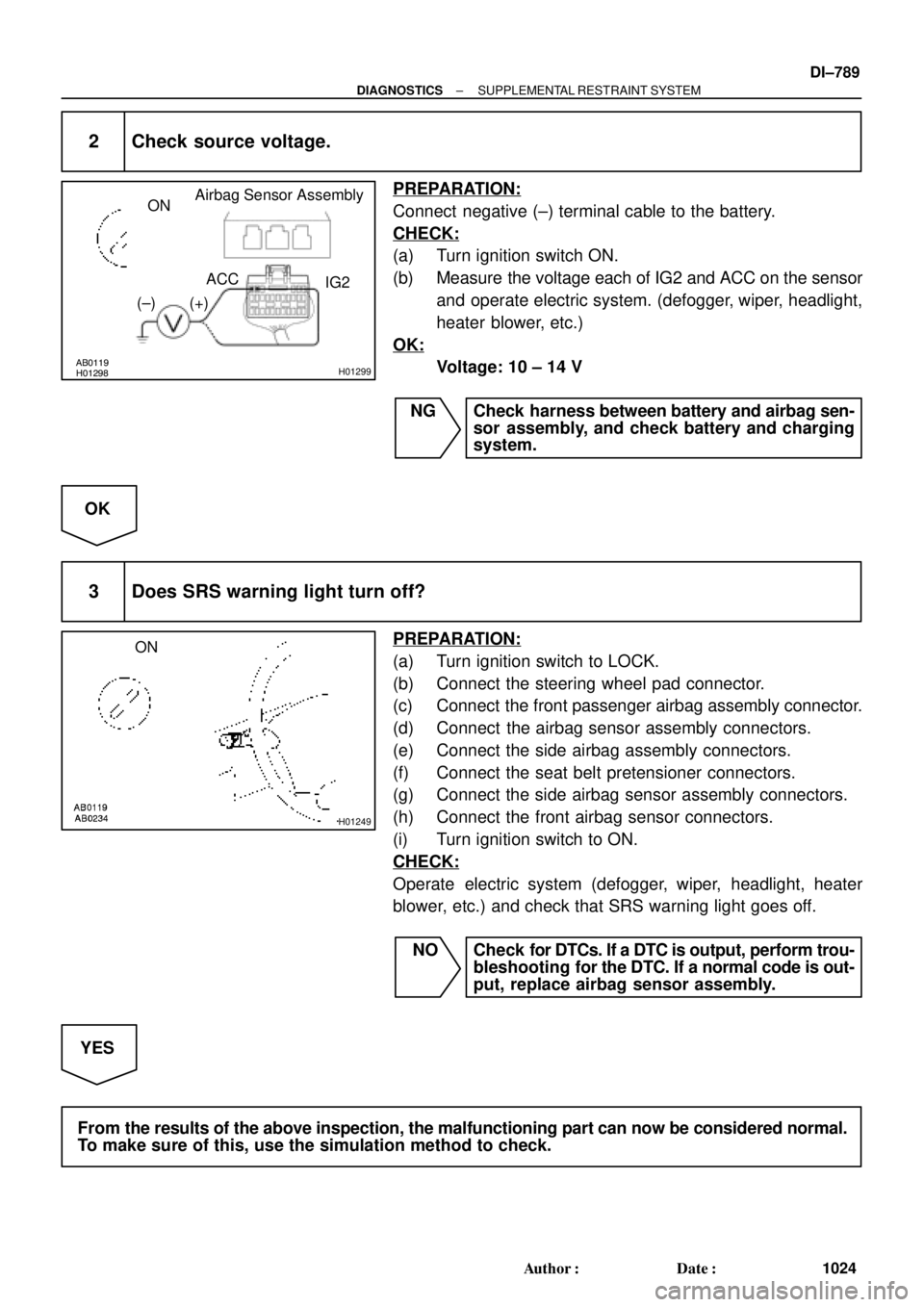
Airbag Sensor Assembly
ON
ACC
IG2
(+) (±)
H01249
ON
± DIAGNOSTICSSUPPLEMENTAL RESTRAINT SYSTEM
DI±789
1024 Author�: Date�:
2 Check source voltage.
PREPARATION:
Connect negative (±) terminal cable to the battery.
CHECK:
(a) Turn ignition switch ON.
(b) Measure the voltage each of IG2 and ACC on the sensor
and operate electric system. (defogger, wiper, headlight,
heater blower, etc.)
OK:
Voltage: 10 ± 14 V
NG Check harness between battery and airbag sen-
sor assembly, and check battery and charging
system.
OK
3 Does SRS warning light turn off?
PREPARATION:
(a) Turn ignition switch to LOCK.
(b) Connect the steering wheel pad connector.
(c) Connect the front passenger airbag assembly connector.
(d) Connect the airbag sensor assembly connectors.
(e) Connect the side airbag assembly connectors.
(f) Connect the seat belt pretensioner connectors.
(g) Connect the side airbag sensor assembly connectors.
(h) Connect the front airbag sensor connectors.
(i) Turn ignition switch to ON.
CHECK:
Operate electric system (defogger, wiper, headlight, heater
blower, etc.) and check that SRS warning light goes off.
NO Check for DTCs. If a DTC is output, perform trou-
bleshooting for the DTC. If a normal code is out-
put, replace airbag sensor assembly.
YES
From the results of the above inspection, the malfunctioning part can now be considered normal.
To make sure of this, use the simulation method to check.
Page 3314 of 4770
N16045
3 4
DI±894
± DIAGNOSTICSCRUISE CONTROL SYSTEM
1129 Author�: Date�:
3 Check control switch.
PREPARATION:
(a) Remove steering wheel center pad.
(b) Disconnect the control switch connector.
CHECK:
Measure resistance between terminals 3 and 4 of control switch
connector when control switch is operated.
Switch positionResistance (W)
Neutral8 (No continuity)
RES/ACC50 ± 80
SET/COAST180 ± 220
CANCEL400 ± 440
NG Replace control switch.
OK
4Check harness and connector between cruise control ECU and cruise control switch,
cruise control switch and body ground (See page
IN±31).
NG Repair or replace harness or connector.
OK
5 Input signal check (See step 1).
OK Wait and see.
NG
Check and replace cruise control ECU
(See page IN±31).
Page 3333 of 4770
N15969
35
± DIAGNOSTICSCRUISE CONTROL SYSTEM
DI±913
1148 Author�: Date�:
2 Check main switch continuity.
PREPARATION:
(a) Remove steering wheel center pad. (See page SR±11)
(b) Disconnect the control switch connector.
CHECK:
Check continuity between terminals 3 and 5 of control switch
connector when main switch is held ON and OFF.
OK:
Switch positionTester connectionSpecified condition
OFF3 ± 5No continuity
Hold ON3 ± 5Continuity
NG Replace control switch.
OK
3 Check harness and connector between cruise control ECU and main switch
(See page IN±31).
NG Repair or replace harness or connector.
OK
Check and replace cruise control ECU
(See page IN±31).
Page 3409 of 4770
EM084±04
S05609
S05249
S05296
S05597
± ENGINE MECHANICAL (5S±FE)TIMING BELT
EM±17
1189 Author�: Date�:
REMOVAL
1. REMOVE GENERATOR (See page CH±6)
2. REMOVE RH FRONT WHEEL
3. REMOVE RH FRONT FENDER APRON SEAL
4. REMOVE PS PUMP DRIVE BELT
Loosen the 2 bolts, and remove the drive belt.
5. DISCONNECT GROUND STRAP CONNECTOR
6. REMOVE ENGINE MOVING CONTROL ROD
Remove the 3 bolts and control rod.
7. REMOVE NO.2 RH ENGINE MOUNTING BRACKET
Remove the 3 bolts and mounting bracket.
8. REMOVE SPARK PLUGS
(a) Disconnect the 4 high±tension cords from the clamps on
the cylinder head cover.
(b) Disconnect the 4 high±tension cords from the spark plug.
(c) Remove the 4 spark plugs.
9. REMOVE NO.2 TIMING BELT COVER
(a) Disconnect the 2 engine wire clamps from the timing belt
cover.
(b) Remove the 4 bolts and timing belt cover.
Page 3420 of 4770

S05596
S05296
S05249
S05609
EM±28
± ENGINE MECHANICAL (5S±FE)TIMING BELT
1200 Author�: Date�:
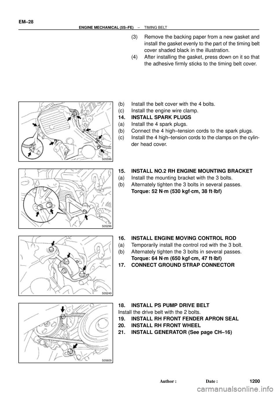
(3) Remove the backing paper from a new gasket and
install the gasket evenly to the part of the timing belt
cover shaded black in the illustration.
(4) After installing the gasket, press down on it so that
the adhesive firmly sticks to the timing belt cover.
(b) Install the belt cover with the 4 bolts.
(c) Install the engine wire clamp.
14. INSTALL SPARK PLUGS
(a) Install the 4 spark plugs.
(b) Connect the 4 high±tension cords to the spark plugs.
(c) Install the 4 high±tension cords to the clamps on the cylin-
der head cover.
15. INSTALL NO.2 RH ENGINE MOUNTING BRACKET
(a) Install the mounting bracket with the 3 bolts.
(b) Alternately tighten the 3 bolts in several passes.
Torque: 52 N´m (530 kgf´cm, 38 ft´lbf)
16. INSTALL ENGINE MOVING CONTROL ROD
(a) Temporarily install the control rod with the 3 bolt.
(b) Alternately tighten the 3 bolts in several passes.
Torque: 64 N´m (650 kgf´cm, 47 ft´lbf)
17. CONNECT GROUND STRAP CONNECTOR
18. INSTALL PS PUMP DRIVE BELT
Install the drive belt with the 2 bolts.
19. INSTALL RH FRONT FENDER APRON SEAL
20. INSTALL RH FRONT WHEEL
21. INSTALL GENERATOR (See page CH±16)
Page 3459 of 4770
S05316
M/T
Engine
No.2 Exhaust
Manifold Stay
(TMMK Made)
(TMC Made)
Exhaust Pipe Bracket
Oil Pan
Insulator
No.1 Exhaust
Manifold Stay
Back±Up Light Switch ConnectorNo.2 Rear End Plate Flywheel
LH Stiffener Plate
Clutch Disk
Clutch Cover
Engine Wire
VSS Connector
Wire Clamp
Ground Strap
Transaxle No.1 Rear End PlateIntake Manifold
Stay RH Stiffener Plate
N´m (kgf´cm, ft´lbf)
� Precoated partx 8
88 (900, 65)
19 (195, 14)
64(650, 47)
64(650, 47)
64(650, 47)64(650, 47)
�
: Specified torquex 6
± ENGINE MECHANICAL (5S±FE)ENGINE UNIT
EM±67
1239 Author�: Date�:
Page 3466 of 4770
S05531
Wire
Bracket
Ground
Strap
S05314
M/T EM±74
± ENGINE MECHANICAL (5S±FE)ENGINE UNIT
1246 Author�: Date�:
38. REMOVE TRANSAXLE
(a) Remove the 4 bolts, ground strap and wire bracket.
(b) Remove the transaxle together with the torque converter
clutch (A/T) from the engine.
39. M/T:
REMOVE CLUTCH COVER AND DISC
40. M/T:
REMOVE FLYWHEEL
Remove the 8 bolts and flywheel.
41. A/T:
REMOVE DRIVE PLATE
Remove the 8 bolts, front spacer, drive plate and rear spacer.
42. REMOVE NO.1 REAR END PLATE
Remove the bolt and end plate.